1
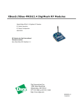
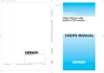
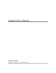
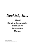
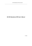
Remote Analog Digital I/O Board User Manual PN: 2040 Berkshire Products, Inc. Phone: 770-271-0088 http://www.bkp-store.com/ Rev: 1.01 © Copyright 2012, 2013 Remote Analog Digital I/O Board User Manual Table of Contents 1 2 3 4 5 6 7 8 Introduction................................................................................................................. 2 Remote 8 Port I/O Board Configuration..................................................................... 3 2.1 Adding Parts........................................................................................................ 3 Making Connections ................................................................................................... 4 3.1 AD/DC Power Input ........................................................................................... 4 3.2 Input / Output Wiring.......................................................................................... 5 3.3 Input / Output Selection Jumpers........................................................................ 5 3.4 Output Ports ........................................................................................................ 6 3.5 Digital Input Ports............................................................................................... 6 3.5.1 Isolated Digital Input Option ...................................................................... 7 3.5.2 Non-Isolated Digital Input Option .............................................................. 8 3.6 Analog Input Ports .............................................................................................. 9 Configuring the XBee Radio .................................................................................... 10 4.1 Starting X-CTU................................................................................................. 11 4.2 Configuring the Networking ............................................................................. 12 4.3 Configuring the Addressing.............................................................................. 13 4.4 Configuring the Serial Interfacing .................................................................... 14 4.5 Configuring I/O Settings................................................................................... 15 4.6 Configuring I/O Sampling ................................................................................ 16 Schematic Diagram................................................................................................... 17 PCB Mechanical ....................................................................................................... 19 Appendix A – Specifications .................................................................................... 20 Appendix B - Warranty............................................................................................. 21 Rev 1.01 i 6/17/2013 Remote Analog Digital I/O Board User Manual The latest versions of manuals, sample code and other tools can be found on our site at: http://bkp-store.com/ If you have any questions, corrections, or feedback about this manual please contact us at: http://bkp-store.com/index.php?route=information/contact Rev 1.01 1 6/17/2013 Remote Analog Digital I/O Board User Manual 1 Introduction The Remote I/O boards are used with XBee1 radio modules to allow remote digital sensing and remote digital output control. These boards are designed to use very little power except when the radios are transmitting data. The board can be used with the following types of XBee & XBeePro radios in Series 1 & 2 footprints: DigiMesh2 2.4G DigiMesh2 900MHz 802.15.4 900MHz 868MHz Zigbee WiFi For best results we recommend that you use XBee radios with the RP-SMA antenna connector or the mini whip antenna. These will experience the least interference from the copper areas on the PCB. The XBee radios with chip and PCB antennas will still work but their range may be reduced. Note 1: XBee is a registered trademark of Digi International Inc. Note 2: DigiMesh is a registered trademark of Digi International Inc. Rev 1.01 2 6/17/2013 Remote Analog Digital I/O Board User Manual 2 Remote 8 Port I/O Board Configuration This board (Base PN: 2040) is offered in 2 configurations: A 4 port analog input and 4 port digital with full I/O capability on all the I/O ports. A 4 port analog input and 4 port digital input only. On these boards Ports 0-3 are the analog inputs and Ports 4-7 are the digital I/O (see Figure 3-1). 2.1 Adding Parts Please note that you if you buy the reduced function set boards, you can easily update them in the field by adding the appropriate input opto-couplers or the solid state relays. The boards are shipped from BPI with the following opto-couplers: Lite-On: LTV-816S The following solid state relays may be used: Vishay: VO14642AAB International Rectifier: PVG612S If you use another vendor's solid state relay it should be able to handle 1A in an AC configuration. Refer to the PDF PCB Assembly drawing for the location of the parts. Rev 1.01 3 6/17/2013 Remote Analog Digital I/O Board User Manual 3 Making Connections Refer to following PCB diagram for component placement. Figure 3-1 3.1 AD/DC Power Input The board can accept DC or AC power input. This can be with stripped wires connected to the screw terminal at J18 or the 2.1mm power connector J17 (see Figure 3-1). The DC supply is not polarity sensitive since the board has a bridge rectifier on the input. DC power is the preferred input type if available. Note: Do not exceed +32V supply input to the board! You can measure the input voltage at TP1 and GND (Pin 3 or 4 on J15). The power supply must able to source enough current to power the board and the XBee radio in TX mode. This will typically be up to 500mA (0.5A) for the higher powered XBee radios. The input pre-regulator on the board is an 80% switcher supplying +5V volts so your input supply needs to provide about 3.1W. If you have a +12V supply then it should be rated at 250mA minimum. Rev 1.01 4 6/17/2013 Remote Analog Digital I/O Board User Manual 3.2 Input / Output Wiring The inputs and outputs are wired to the connectors J4 and J11 (Phoenix Contact PN: 1990067). They will accept stripped wire in the range of 20-26 gauge. The bottom of the connector is Pin 1 and the top is Pin 8 (See Figure 3-1). Use a small flat screwdriver to push down on the wire release tab, insert or extract the wire, and then release the tab. The following table shows the Port Numbers and the connections to the I/O connectors and the destination pin on the XBee radio: Port # 0 1 2 3 4 5 6 7 Input J11-1 AIN0 / J11-2 AGND J11-3 AIN1 / J11-4 AGND J11-5 AIN2 / J11-6 AGND J11-7 AIN3 / J11-8 AGND J4-1 + / J4-2 J4-3 + / J4-4 J4-5 + / J4-6 J4-7 + / J4-8 - Output J11 – Pins 1-2 J11 – Pins 3-4 J11 – Pins 5-6 J11 – Pins 7-8 J4 – Pins 1-2 J4 – Pins 3-4 J4 – Pins 5-6 J4 – Pins 7-8 XBee Port DIO0 – Pin 20 DIO1 – Pin 19 DIO2 – Pin 18 DIO3 – Pin 17 DIO4 – Pin 11 DIO5 – Pin 15 DIO6 – Pin 16 DIO7 – Pin 12 Table 3-1 3.3 Input / Output Selection Jumpers Each of the upper 4 ports on the board can be configured to be an input OR output only. This is done by placing 0.100” jumpers on the headers listed in the table below: Port # 4 5 6 7 Input Header1 J6 (1-2 or 2-3) J5 (1-2 or 2-3) J3 (1-2 or 2-3) J1 (1-2 or 2-3) Output Header J10 – Pins 1-2 J10 – Pins 3-4 J10 – Pins 5-6 J10 – Pins 7-8 Table 3-2 Note 1: See section 3.5 for input options. Do not place jumpers on input and output headers for the same port. You may get indeterminate results. Rev 1.01 5 6/17/2013 Remote Analog Digital I/O Board User Manual 3.4 Output Ports The output ports are controlled by solid state relays that can switch a maximum of 1.0Amps. Their outputs are fused with resettable fuses that trip at 1.5A and hold at 0.75A. The fuses used are rated at 30V MAX. The absolute maximum voltage that should be switched is 24V DC or AC. DO NOT SWITCH HIGHER VOLTAGES OR HIGHER CURRENTS THAN SPECIFIED. THE BOARD DOES NOT HAVE TRACES WIDE ENOUGH FOR HIGHER CURRENTS OR TRACES SPACED FAR ENOUGH APART FOR HIGHER VOLTAGES! DOING SO COULD POSE A RISK OF FIRE OR ELCTROCUTION. Writing a one (1) value to an XBee pin configured as an output causes the solid state relay to turn on. Writing a zero (0) value to an XBee pin configured as an output cause the solid state relay to turn off. The board has pull-down resistors on the relay driver IC input pins so that the relays will be off at power up or off if the port is configured to be an input. 3.5 Digital Input Ports The input ports are implemented with opto-couplers. The current through the LED in the opto coupler is limited by a series 1.30K Ohm 1/2W resistor. The minimum voltage that will turn on the opto is about 3.0V. The resistor is rated at 1/2W, so that limits the maximum input voltage to 24V DC. The opto is not designed for an AC input and it will fail if you apply an AC voltage greater than 5.0V. The input circuit uses opto-couplers with an emitter follower transistor output. When current flows in the input circuit LED, the output transistor turns on, driving the input pin on the XBee high or to one (1) and the XBee will send the input status as one (1). When input LED current is removed, the transistor turns off and its emitter is pulled low so the XBee radio will send the input status as a zero (0). Note: Refer to Table 3-1 and Figure 3-1 to be sure you connect the plus (+) and minus (-) DC inputs correctly for each port. The next two sections cover connecting the inputs for isolated or non-isolated options. Rev 1.01 6 6/17/2013 Remote Analog Digital I/O Board User Manual 3.5.1 Isolated Digital Input Option This figure shows an isolated input using an external switch and an external power source. In this example the shorting jumper is on Pins 2-3 of J6 for Port 4. In this case when the external switch is closed, current flows from the DC source into Pin 1 of J4, through the limit resistor (1.30K – R8), through the opto LED, back through the fuse which is always in the circuit, through Pin 2 of J4 and back to the DC source. The relay (U7) is off and is high impedance so it does not affect the circuit. Figure 3-2 This type of configuration is preferred since it protects the board in cases where the input wiring comes in contact with a high voltage wire. If the input wire did come in contact with a high voltage it would probably only blow the opto coupler. The disadvantage to this circuit is that it requires an external DC source. Rev 1.01 7 6/17/2013 Remote Analog Digital I/O Board User Manual 3.5.2 Non-Isolated Digital Input Option This figure shows a non-isolated input. In this example the shorting jumper is on Pins 1-2 of J6 for Port 4. In this case the on-board +5V-IO becomes the DC source for the opto LED current and J-16 (GND TIE) becomes the DC return path. When the external switch is closed, current flows from +5V-IO source through Pins 1-2 of J6, through the limit resistor (1.30K – R4), through the opto LED, back through the fuse which is always in the circuit, through Pin 2 of J4 and back to the DC source GND at J16. The relay (U7) is off and is high impedance so it does not affect the circuit. Figure 3-3 This type of circuit is simpler to implement since it only requires a dry closure switch. Note: If you use this circuit, be sure your wiring is safe and can not come in contact with any high voltage potential! Rev 1.01 8 6/17/2013 Remote Analog Digital I/O Board User Manual 3.6 Analog Input Ports The board has 4 analog input ports. Port 0 is shown below: Figure 3-4 Each analog input allows for two voltage input ranges. When the 3 pin jumper (J14 for Port 0) is shorted on pins 1-2, the input range can be 0.0V to +5.0V. The output of the OP-Amp will be 3.25V when the input is +5.0V which will be just below the +3.3V maximum input allowed on the XBee radio. When J14 is shorted on pins 2-3 the input range is 0.0V to +24V. The output of the OP-Amp will be 3.25V when the input is +24.0V. Note: Do not exceed the maximum input voltages on either range or apply negative voltages on the inputs. The dual Shottky diode is there to protect against over-voltage and negative voltages up to a point. Note: The input impedance of the analog inputs is the serial parallel combination of the 4 resistors or 35.8KΩ. Rev 1.01 9 6/17/2013 Remote Analog Digital I/O Board User Manual 4 Configuring the XBee Radio The examples shown here use an XBee 2.4G DigiMesh version with Digi’s X-CTU software which is free and available from Digi International (www.digi.com). To program the radios we use the UARTSBee V4 device which provides power and a USB UART connection to the PC. They are available from Amazon (www.amazon.com) and other sources and look similar to this picture: Figure 4-1 These devices are also useful for connecting to your PC to use as the “base station” to talk back and forth with the remote I/O module’s XBee radio. Note: Be aware that this board may not be able to supply enough power for an XBee Pro type radio if you plug it into a USB hub. Note: When the device is first plugged in you may get an alert from your PC that it needs to install drivers for a new device. The UARTSBee uses the FTDI chip for USB to Serial conversion and most PCs have these drivers pre-installed. If yours doesn’t, go to www.ftdi-chip.com to get the latest ones for your PC and OS. Rev 1.01 10 6/17/2013 Remote Analog Digital I/O Board User Manual 4.1 Starting X-CTU When you start X-CTU you should see a screen like the following: Figure 4-2 In this example the USB → Serial was on COM4. The baud rate should be 9600 to start with, since that is how the XBees are shipped from Digi. Click the Test / Query button to see if the XBee is active. If so, you should get a window like this: Figure 4-3 Is this case the test was OK. It found an XB24 or a 2.4G DigiMesh. If it had been the higher power Pro it would have been XBP24. The firmware version is shown along with its serial number (IEEE Address) which is HEX: 0013A200 40870B85. The address is always 8 Bytes (64 bits) and leading zeros are not shown. Most Digi XBees start with 0013A200. It is also shown on the label on the bottom of the module. Rev 1.01 11 6/17/2013 Remote Analog Digital I/O Board User Manual 4.2 Configuring the Networking The next step is to click the Modem Configuration tab and then press the Read button to get a screen like the following: Figure 4-4 Under the Networking section there are options that you can change. Note that different types of modules will have different options. The ones shown here are for DigiMesh. For this module type the only two changes that we will talk about are the VID and the Channel. Modem VID: This is a HEX number that sets the PAN (Personal Area Network) ID for the network. Valid range is 0-0xFFFF. All the XBees on your network should use the same VID. Operating Channel: This sets the operating channel number (Uses 802.15.4 channel numbers). Note two things here: 1. XBee modules have more channels available than XBee Pro modules, so be sure to select an operating channel that both types can use if you have mixed modules on your network. 2. Select a channel number that minimizes conflict with any Wi-Fi networks you have. There are docs on the web that show 802.15.4 channel assignments. See the Digi manual for specifics on other networking options. Rev 1.01 12 6/17/2013 Remote Analog Digital I/O Board User Manual 4.3 Configuring the Addressing XBee modules talk to each other using their serial numbers or a 16 bit addressing scheme. We will show the 802.15.4 64 bit scheme here. The Digi XBee manuals show you how to use short addresses. Figure 4-5 In this example we are programming a module for an I/O board that will talk to a host module (base station) at regular intervals. So in this case we set the High order 4 Bytes to the standard XBee address of 0x0013A200 and the lower 4 bytes to the address of our base station module 0x40883039. Once this is set, the module will know what address to send API packets to when an input changes or when a sample must be sent. Rev 1.01 13 6/17/2013 Remote Analog Digital I/O Board User Manual 4.4 Configuring the Serial Interfacing There are a few options to set here: Figure 4-6 One option that needs setting here is the API enable. API mode must be enabled if the XBee module on the I/O board is going to be able to transmit input pin information and set the outputs. API mode 2 is used by the Arduino XBee library if you plan to use an Arduino type board as your base station. Also note that the Digital I/O pins DIO6 and DIO7 are configured here. The reason for that is they can also be used as serial port flow control pins. If you are using DIO6 and DIO7 on your module then you should configure them here as Inputs or Outputs. Rev 1.01 14 6/17/2013 Remote Analog Digital I/O Board User Manual 4.5 Configuring I/O Settings Here is where you configure the I/O pins for DIO0 to DIO5 (see prior section for DIO6 & DIO7): Figure 4-7 Configure DIO0 to DIO5 pins as input or output to match your I/O board setup. DIO8 to DIO12 are not used and should be left as 0-Disabled. The PR field defaults to 0x1FFF or binary 1 1111 1111 1111. Each bit set to one (1) defines a pull-up resistor on input pins DIO12 to DIO0. The default values should be fine unless you are using the input pins for analog inputs. In that case the lower six bits should be zero for any pin that is an analog input. Rev 1.01 15 6/17/2013 Remote Analog Digital I/O Board User Manual 4.6 Configuring I/O Sampling This is the last area of X-CTU covered here: Figure 4-8 The DIO Change Detect is a bit field and should be set to a hex value. Any bit that is set will cause the XBee to send a packet when the I/O line for that bit changes (goes low to high or high to low) and the pin is set as an input. For example if you set this field to 0x2C (binary 0100 1100) then it would send a data packet if DIO6, DIO3 or DIO2 changes state on its input. The Sample Rate tells the XBee module to send a data packet at regular intervals to report the status of digital and analog input pins. The number is in milliseconds so a reasonable minimum value is about 0x80 or 128mS. If an edge change is programmed and it occurs between samples then a packet will be sent then as well. The maximum value for this field is 0xFFFF or 65,353mS. A value of zero stops the samples. Rev 1.01 16 6/17/2013 Remote Analog Digital I/O Board User Manual 5 Schematic Diagram Rev 1.01 17 6/17/2013 Remote Analog Digital I/O Board User Manual Rev 1.01 18 6/17/2013 Remote Analog Digital I/O Board User Manual 6 PCB Mechanical Note: Dimensions are in mils. Rev 1.01 19 6/17/2013 Remote Analog Digital I/O Board User Manual 7 Appendix A – Specifications Power Requirements: 8V @ 400mA – minimum 32V maximum @ 100mA Do not exceed +32V input. The Input DC voltage (after the bridge rectifier) can be monitored at TP1 (see Figure 3-1) on the board. Environmental: -40° to +85°C - Operating -40° to +85°C - Storage 5% to 95% Relative Humidity, non-Condensing Digital Input Port DC Polarized +24VDC maximum +3.0DC minimum Digital Output Port Opto Solid State relay 1.0A Maximum AC or DC Analog Input Port 0.0 - +5.0 Input (jumper pins 1-2) 0.0 - +24.0V Input (jumper pins 2-3) Rev 1.01 20 6/17/2013 Remote Analog Digital I/O Board User Manual 8 Appendix B - Warranty Berkshire Products, Inc. warrants to the original consumer or other end user purchaser that this product is free from defects in materials or workmanship for a period of one (1) year from the date of purchase. During the warranty period, and upon proof of purchase, the product will be repaired or replaced (with the same or functionally equivalent model) at our option, without charge for either parts or labor. This warranty does not apply to defects due directly or indirectly to misuse, abuse, negligence, accident, repairs or alterations made by the customer or another party. UNDER NO CIRCUMSTANCES WILL BERKSHIRE PRODUCTS, INC. BE LIABLE IN ANY WAY TO ANY PURCHASER FOR DAMAGES, LOST REVENUE, LOST WAGES, OR ANY OTHER INCIDENTAL OR CONSEQUENTIAL DAMAGES ARISING OUT OF THE USE OR INABILITY TO USE THIS PRODUCT. Berkshire Products, Inc. reserves the right to make modifications in this product without prior notification. Rev 1.01 21 6/17/2013