1
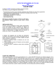
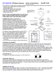
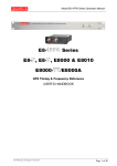
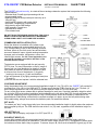
STK-3302PET PIR Motion Detector
INSTALLATION MANUAL
SAMTEK
SECURITY SYSTEMS
The 3302PET with pet immunity, is a state-of-the-art analogue detection system that incorporates the following
unique features:
- Patented Auto Pulse® signal processing with two
programmable levels
- Specially designed lens provides pet immunity up to
18kg (40 lbs)
For ANPI listed installation,
- Improved RFI rejection with metal shield
The plastic cover enclosure
must be closed with a
- Automatic Temperature Compensation
screw.
- High density reflow SMD design
- Lodif segment Fresnel lens
- Optional other lenses
- Fire resistant case
DO NOT TOUCH THE SENSOR SURFACE AS THIS COULD
RESULT IN DETECTOR MALFUNCTION. IF NECESSARY,
CLEAN USING A SOFT CLOTH AND PURE ALCOHOL.
COMMENCING INSTALLATION (FIG-1)
Select the detector’s installation site, based on the
required coverage and recommended height of 2.1m
(7ft). Avoid proximity to any of the following: reflective
surfaces, direct air flow from vents, fans and windows,
sources of steam/oil vapor, objects causing temperature
changes such as heaters, refrigerators, ovens, and
infrared light sources. For CUL Listed applications, the
unit shall be installed in accordance with Part I of the
Canadian Electrical Code.
The detector comes equipped with the pet immunity
(PET-2) lens. For more information on the full range of
lenses, ask your local distributor for details. If another
lens pattern is required, choose the desired lens and:
a) remove front cover of the detector (1) by gently
pushing in the cover pin (2) with a screwdriver.
b) pull out the bezel (4) by lightly pressing on bezel pins
(5) and (6).
c) remove the lens and replace it with the alternate lens.
COVERAGE ADJUSTMENT
Using the standard lens at the recommended installation height of 2.1m (7ft) ±10%, the 3302PET will provide full
coverage from 1.2m (4ft) to 11m (35ft) at 20oC. Please ensure that the PCB is fixed at the 2.1m (7ft) mark. (A
small vertical adjustment of the PCB (±0.5mm) may be required. Refer to FIG-4 on other side)
For any of the other lenses, please refer to pattern drawings for each lens. If another installation height is called
for, move the PCB to the proper installation height indicated on the left side of the PCB. A small adjustment may
be required, depending on the protected area. Any PCB adjustment should be followed by a walk-test of the
protected area. Walk-testing verifies that the required coverage is in place, as per the lens pattern being used.
When walk testing, always move across the detection path, not toward the detector.
PET ALLEY
To create a pet "alley" using the pet alley lens, the recommended installation height is slightly above the maximum
area occupied by the pet. The PCB should be set at the 2.1m (7ft) mark, regardless of the installation height for
this lens.
LED SETTING (J1)
To disable the LED display, set jumper J1 to OFF (see FIG-1).
SLOW/FAST MODE (J2)
Jumper J2 is located inside the metal shield and is factory-set to the "ON" position (fast mode), which is
recommended for the majority of installations. The use of slow mode (jumper “OFF”) is suggested in areas where
the incidence of false alarms may be greater. To access Jumper J2, use a small screwdriver to gently pry off the
metal shield (10). Please refer to FIG-1.
TURNING ON THE 3302PET
Apply power by connecting the “AUX+” and “AUX-” of the control panel to the “+” and “-” terminals of the detector
(FIG-3). Powering the detector initiates a self-testing program for the signal processor, memory and relay. The
green LED will flash for a period of 35 seconds and the relay will follow the status of the LED.
AUTO PULSE SIGNAL PROCESSING
Patented Auto Pulse® Signal Processing provides a variable pulse count rate, in response to signal shape,
strength and width. The 3302PET will immediately generate an alarm for very strong signals, or switch
automatically to pulse counting as signals become weaker. The 3302PET motion detector permits a very high
pulse count rate (up to 6 or more) in the presence of low level signals.
AUTO TEMPERATURE COMPENSATION
These detectors are equipped with "automatic temperature compensation" (ATC), which adjusts amplifier gain to
maintain coverage levels across a wide range of temperatures.
WALK-TESTING
In “fast” mode (J2=ON), at 20oC , you should not be able to cross more than one complete zone (consisting of two
beams left and right sensor detecting elements) in the coverage area with any kind of movement; slow/fast
walking or running. In slow mode (J2=OFF), the amount of movement required to generate an alarm is doubled.
The approximate width of a full beam at 11m (35ft) from the detector is 1.7m (6ft). Please note when the indoor
temperature is higher than 25oC, the detection distance will be shorter.
IMPORTANT NOTES
The detector cover must be installed properly when conducting walk tests. The unit shall be tested annually by the
installer in order to comply with UL-639. Only the WA-1 standard lens was tested to UL-639.
The unit is intended to be connected to a UL listed control unit or power supply which supplies a minimum of 4
hours of standby power.
WARRANTY
The Seller warrants its products to be free from defects in materials and workmanship under normal use for a
period of one year. Except as specifically stated herein, all express or implied warranties whatsoever, statutory or
otherwise, including without limitation, any implied warranty of merchantability and fitness for a particular purpose,
are expressly excluded. Because Seller does not install or connect the products and the products may be used in
conjunction with products not manufactured by Seller Seller cannot guarantee the performance of the security
system. Seller obligation and liability under this warranty is expressly limited to repairing or replacing, at Seller's
option, any product not meeting the specifications. In no event shall the Seller be liable to the buyer or any other
person for any loss or damages whether direct or indirect or consequential or incidental, including without
limitation, any damages for lost profits stolen goods, or claims by any other party, caused by defective goods or
otherwise arising from the improper, incorrect or otherwise faulty installation or use of the merchandise sold.
TECHNICAL SPECIFICATION
Sensor
Processing
Startup
Detection Speed
Operating Temperature
Power Input
Lens
Coverage
Pet Immunity
Mounting Height
Alarm Indication
Alarm Output
Anti-tamper Switch
Humidity
Weight
Dual rectangular element, low noise, high
sensitivity
Auto Pulse, two levels, temperature
compensation
35 seconds
0.2m-7m/sec (0.6-23 ft/sec.)
-100C to +500C (140F to +1220F)
12Vdc, 31mA maximum
2nd generation Fresnel lens
35’(11m) x 88.50 up to 15m at centre area
No alarm for pet under 18KG
7- 9 ft (2.1m - 2.7m)
Blue LED, constant light for 3 seconds
N.C. 28Vdc / 0.15A
N.C. 28Vdc / 0.15A Max
95% maximum
75g (2.6oz)
FIG-4