1
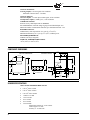
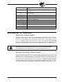
£
E-3451
JUNE 1999
E340 BOILER
CONTROL
INSTALLATION MANUAL
DESCRIPTION
The E340 Boiler Room Control is a microprocessor-based Boiler Management System designed to
interface with existing Fireye “D” Series and FLAME-MONITOR Flame Safeguard control systems,
as well as competitive flame safeguard systems. The E340 Boiler Room Control system consists of a
Chassis, Plug-in Programmer Module, Plug-in Keypad/Display Module (for system configuration and
display of system setpoints and operating parameters), Wiring Base, Solid State Sensors (gas, steam,
and oil pressure, fuel oil and water temperature), and remote communications software.
Functions provided by the E340 include operating control function, modulating control function,
safety limits (with the exception of high steam pressure or high hot water temperature), cold start thermal shock protection, lead/lag operation of two boilers, time-of-day clock for setback operation,
remote communications capability using an IBM compatible PC, etc.
Refer to Bulletin E-3401 for a complete technical description of the monitoring and control capabilities of the E340, as well as information on the set-up and programming of the control. This bulletin
provides information on system specifications, component dimensions, and the installation and wiring
of the E340 Boiler Room Control. Refer to Bulletin ES-3481 for information on the installation and
wiring of the pressure and temperature sensors. Refer to Bulletin E-7201 for information on the installation, set-up, and operation of the remote communication software program.
SYSTEM SPECIFICATIONS
SUPPLY VOLTAGE: 24 VAC (+10%, -15%)
OPERATING TEMPERATURE LIMITS:
-40qF (-40qC) to 140qF (60qC) (without keypad/display module)
15qF (-9qC) to 131qF (55qC) (with keypad/display module)
OPERATING HUMIDITY LIMITS: 5% to 85% Non-condensing @ 0qC to 60qC
RELAY OUTPUTS:
2 Line voltage normally open (NO) isolated outputs rated at 5 amps @ 120 VAC, 1/3 HP.
Maximum connected load for each relay is 600 VA.
2 Low voltage, normally open (NO) outputs rated at: 5 amps @ 24 VAC or VDC,
internally connected to Terminal 41.
DIGITAL INPUTS: 4 Line voltage digital inputs (120 VAC).
3 Low voltage dry contact inputs
1 Low voltage resistive input (0-135:).
£
ANALOG OUTPUTS:
2 Analog outputs, 4-20 mA signal, 8 bit resolution.
Maximum connected load = 750 ohms.
ANALOG INPUTS:
3 Pressure Inputs, 1-5 VDC input control signal, 12 bit resolution
2 Temperature Inputs, 1,000:@ 0qC, 12 bit resolution
COMMUNICATIONS:
Protocol is Fireye half-duplex DF1 or MODBUS
EIA standard RS485 serial link using 22 gauge twisted shielded pair wire.
Maximum number of addressable controllers per communication link = 255.
BATTERY BACKUP:
Lithium battery with expected life of 5 years @ 77qF (25qC).
Maintain RAM memory for 1 year @ 77qF (25qC) without power.
POWER REQUIREMENTS:
20 Watts (All relays energized)
STORAGE TEMPERATURE LIMITS:
-40qF (-40qC) to 158qF (70qC)
COMPONENT DIMENSIONS
CONTROL WITH COVER AND
P/N E343 WIRING BASE
WIRING BASE
MOUNTING HOLES
5 11/
16
2 7/16
(61.9)
3 5/8 (92)
1 7/8
(48)
KNOCKOUTS
FOR
7 9/32
(185)
3 7/32
(82)
7
(177.8
3/4
(44.4) 25/32
(19.8)
1/2” KNOCKOUT
6
(152)
1 1/16
(27)
OIL/GAS/STEAM PRESSURE RANGES:
x
x
x
x
x
x
x
x
1/4
TYP
(6.35)
1 3/16
(30.2)
SENSOR SPECIFICATIONS
2
5 1/4
(133)
5 3/4
(146)
0 to 16s water column
0 to 32swater column
0 to 160s water column
1.0 PSI to 17.0 PSI
1.0 to 33.0 PSI
10 to 170 PSI
10 to 330 PSI
50 to 850 PSI
All Pressure Sensors are 3-wire sensors.
Control signal: 1-5 VDC
Accuracy: r1% full scale
4 7/8
(123.8
390
TYP
(9.9)
11/16
(17.4)
£
TEMPERATURE RANGES
x
x
32qF to 750qF
0qC to 400qC
Reference resistance: 1000 ohms @ 0qC
Temperature coefficient:.00385/:/:/qC
Accuracy: r2qF (1qC)
ORDERING INFORMATION
PART NUMBER
DESCRIPTION
CONTROL COMPONENTS
E340
Boiler Room Control. (Includes Chassis, Keypad/Display Module, and Dust Cover)
EP340
Programmer Module for E340 Boiler Room Control
EB342
Chassis for E340 Boiler Room Control
E343
Wiring Base for E340 Boiler Room Control (surface mounted - UL Listed)
E344
Wiring Base for E340 Boiler Room Control (cabinet mounted - UL Recognized)
E345
Keypad/Display Module for E340 Boiler Room Control
60-2223
Dust Cover
SOLID STATE SENSORS
PS348-1
Pressure Sensor. Range: 0-16s Water Column
PS348-2
Pressure Sensor. Range: 0-32s Water Column
PS348-3
Pressure Sensor. Range: 0-160s Water Column
PS348-4
Pressure Sensor. Range: 1-17 psig
PS348-5
Pressure Sensor. Range: 1-33 psig
PS348-6
Pressure Sensor. Range: 10-170 psig
PS348-7
Pressure Sensor. Range: 10-330 psig
PS348-8
Pressure Sensor. Range: 50-850 psig
TS348-2
Temperature Sensor. Range: 32q-750qF / 0q-400qC. 2s Probe Length
TS348-4
Temperature Sensor. Range: 32q-750qF / 0q-400qC. 4s Probe Length
TS348-8
Temperature Sensor. Range: 32q-750qF / 0q-400qC. 8s Probe Length
3
£
E340 ORDERING INFORMATION
Mounting Screw
48-1805
E340 consists of:
EB342 - Chassis
EB342 - Keypad/ Display Module
60-2223 - Dust Cover
Mounting Screw
60-2223 Dust Cover
EP340 Programmer Module
E345 Keypad/ Display Module
Wiring Base
E343 Surface Mounted
E344 Cabinet Mounted (shown)
4
£
SYSTEM INPUTS AND OUTPUTS
RELAY OUTPUTS:
The E340 provides 4 digital outputs to perform the following functions:
• Operating Control output wired in series with existing external operating limits to operating
control circuit of the flame safeguard control. (Terminals L1 & 13 of FLAME-MONITOR and
D-Series Control).
Rated at 5 amps @ 120 VAC.
Normally Open (NO) isolated output.
• Safety Circuit wired in series with existing external running interlocks to running interlock
circuit of the flame safeguard control. (Terminals 3 & P of FLAME-MONITOR and
D-Series Control).
Rated at 5 amps @ 120 VAC.
Normally open (NO) isolated output.
• Marginal Alarm output relay: Rated at 5 amps @ 24 VAC.
• Auxiliary Relay output: Rated at 5 amps @ 24 VAC.
DIGITAL INPUTS:
The E340 provides 8 digital inputs to monitor the following inputs:
• Fuel selector switch for gas operation. Rated at 120 VAC
• Fuel selector switch for oil operation. Rated at 120 VAC.
• Fuel selector switch for heavy oil operation. Rated at 120 VAC.
• Status of Main Fuel Valve. Rated at 120 VAC.
• Input to determine Lead/Lag operation. Dry Contact Only.
• Position of the Firing Rate Damper Motor. Resistive input (0-135:).
• Input to Initiate Setback Mode. Dry Contact Only.
• Input to Override Setback Mode.Time determined by user. Momentary Dry Contact Only.
ANALOG INPUTS:
The E340 provides 5 analog inputs to monitor the following:
INPUT
PRESSURE SENSORS
MARGINAL ALARMS & ALARM LIMITS
1
Gas Pressure
High and Low
2
Oil Pressure
High and Low
3
Steam Pressure
High and Low*
INPUT
4
5
DESCRIPTOR
PRIMARY
AUXILIARY
TEMPERATURE
SENSOR OPTIONS
MARGINAL ALARMS
& ALARM LIMITS
Primary Water Temp.
High and Low*
Standby Water Temp.
None
Stack Temp
High Only
Outdoor Temp.
None
Oil Temp.
High and Low
Stack Temp.
High Only
Outdoor Temp.
None
* Low marginal alarm only. No low alarm limit.
5
£
ANALOG OUTPUTS:
The E340 provides 2 analog outputs (4-20 mA) to provide the following:
• Proportional control of the Firing Rate Damper Motor.
• Selectable Output Signal based on the value of one of the 5 analog inputs.
WIRING CONNECTIONS
All wiring must beet local and National Electrical Codes. The fish paper insulator covering the Left
Terminal block is provided to isolate its line voltage loads from the low voltage loads connected to
the Right Terminal Block and Sub-miniature Terminal block. (Shaded area denotes line voltage connections.
TERMINAL
LEFT TERMINAL BLOCK - LINE VOLTAGE
50
Running Interlock - FSG Control (Relay Output)
51
Running Interlock - FSG Control1 (Relay Output)
52
Operating Control - FSG Control2 (Relay Output)
53
Operating Control - FSG Control2 (Relay Output)
54
L2 (Neutral) - FSG Control3
55
Main Fuel Valve - FSG Control4 (Digital Input)
56
Fuel Selector Switch - Hvy Oil (Digital Input)
57
Fuel Selector Switch - Oil (Digital Input)
58
Fuel Selector Switch - Gas (Digital Input)
1 Terminals
3 and P of Fireye FLAME-MONITOR and D-Series Flame Safeguard Controls.
L1 and 13 of Fireye FLAME-MONITOR and D-Series Flame Safeguard Controls.
3 Terminal L2 of Fireye FLAME-MONITOR and D-Series Flame Safeguard Controls.
4 Terminal 7 of Fireye FLAME-MONITOR and D-Series Flame Safeguard Controls.
2 Terminals
TERMINAL
40
Earth Ground
41
24 VAC (Hot)
42
24 VAC (Common)
43
Alarm Output (Marginal and Alarm)
44
Auxiliary Relay Output
45
4 - 20 mA Analog Output - Firing Rate Motor ( + )
46
4 - 20 mA Analog Output - Firing Rate Motor ( - )
47
4 - 20 mA Selectable Analog Output ( + )
48
4 - 20 mA Selectable Analog Output ( - )
TERMINAL
6
RIGHT TERMINAL BLOCK - LOW VOLTAGE
SUB-MINIATURE BLOCK - LOW VOLTAGE
60
+24 VDC (Gas Pressure)
61
Sensor Return Line (Gas Pressure)
62
Gas Pressure Sensor
63
+ 24 VDC (Oil Pressure)
64
Sensor Return Line (Oil Pressure)
65
Oil Pressure Sensor
66
+ 24 VDC (Steam Pressure)
67
Sensor Return Line (Steam Pressure)
68
Steam Pressure Sensor
69
Water Temperature (or Outdoor Air, Stack, or standby Temp.) Sensor
£
70
Water Temperature (or Outdoor Air, Stack, or standby Temp.) Return
Line
71
Auxiliary Temperature Sensor (for Oil Temp. Stack Temp., or Outdoor
Air Temp.)
72
Auxiliary Temperature Return Line (for Oil Temp. Stack Temp., or Outdoor Air Temp.)
73
Damper Motor Position Feedback
74
Damper Motor Position Feedback
75
Forced Setback
76
Return Line - Digital Inputs
77
Lead/Lag Selector
78
Return Line - Digital Inputs
79
Setback Override
80
RS-485 Remote Communication Line (B)
81
RS-485 Remote Communication Line (A)
WIRING CONNECTIONS - LEFT TERMINAL BLOCK
Safety Circuit - Terminals 50 and 51
The Safety Circuit relay (Terminals 50 and 51) is wired in the running interlock circuit of the Flame
Safeguard Control (Terminals 3 and P of the FLAME-MONITOR and D-Series controls). The safety
circuit relay is wired in series with any other running interlock circuit (e.g.: high and low water cutoff, etc.). To help limit electrical noise frequencies, the safety circuit relay should be the first circuit
wired in the running interlock circuit of the flame safeguard control. Refer to diagram below. See
SEQUENCE OF OPERATION - HIGH AND LOW ALARM LIMITS section in Bulletin E-3401.
WARNING: An electro-mechanical steam pressure (or hot water) high limit switch
MUST REMAIN in the running interlock circuit of the flame safeguard control.
Operating Control Circuit - Terminals 52 and 53
The Operating Control (Terminals 52 and 53) is wired in the operating control circuit of the Flame
Safeguard Control (Terminals L1 and 13 of the FLAME-MONITOR and D-Series controls). The
operating control is wired in series with any other operating control limit (e.g. burner on/off switch).
The operating control should be the first circuit wired in the operating control circuit of the flame
safeguard control after the burner on/off switch (if applicable). Terminals 52 and 53 should be
wired in the same location as the operating control would normally be found. Refer to diagram
below. See SEQUENCE OF OPERATION - OPERATING CONTROL section in Bulletin E-3401.
7
£
FLAME-MONITOR
TERMINALS
P
E340
TERMINALS
EXTERNAL
RUNNING
INTERLOCKS
3
13
50
E340
INTERNAL
WIRING
51
OPERATING
CONTROL
LIMITS
L1
52
53
BURNER
ON/OFF
120 VAC Neutral (L2) - Terminal 54
To insure proper voltage reference between the E340 and flame safeguard control, Terminal 54 is
wired to the 120 VAC Neutral connection of the flame safeguard control (Terminal L2 of the
FLAME-MONITOR and D-Series control).
Main Fuel Valve - Terminal 55
Terminal 55 is wired to the main fuel valve connection of the flame safeguard control. (Terminal 7 of
the FLAME-MONITOR and D-Series control).
Fuel Selector Switch - Terminals 56, 57, and 58
The E340 has three line voltage inputs (Terminals 56, 57, and 58) to monitor the status of a fuel
selector switch that determines which pressure and temperature sensors the E340 control will monitor. For example, if the selector switch is in the position for “Oil”, the E340 control will disregard the
high and low alarm limits for gas pressure.
Note: When “Heavy Oil” is selected, both the Oil and Heavy Oil inputs must be made.
Note: If the associated sensor is programmed as UNUSED, the input is ignored.
Note: If fuel selection is not detected (all inputs open, E340 displays NONE for Fuel Selected), the
E340 will remain at low fire.
WIRING CONNECTIONS - RIGHT TERMINAL BLOCK
Earth Ground - Terminal 40
A good earth ground is essential in the proper operation of the E340 Control.
Powering the Control (24 VAC) - Terminals 41 (Hot) and 42 (Common)
The E340 control is powered by 24 VAC connected to Terminals 41 (Hot) and 42 (Common). The
power requirements of the E340 control is 20 VA. The alarm output (Terminal 43) and the auxiliary
relay output (Terminal 44) are internally connected to Terminal 41, so the total connected load to
Terminals 43 and 44 should be considered when determining the total VA rating of the control transformer. The additional load of the mod motor should also be taken into account if powered by the
same control transformer.
CAUTION: To insure proper operation, a ZTAH Transient Voltage Surge Suppressor by
Power Integrity Corp., Greensboro, NC, or equivalent should be installed.
8
£
Alarm Output - Terminal 43
The E340 has a low voltage output (Terminal 43) internally connected to Terminal 41 to serve as a
marginal alarm (pulsed output) and lockout alarm (maintained output) if any of the marginal alarm
or lockout alarm limits are exceeded. See SEQUENCE OF OPERATION - HIGH AND LOW
ALARM LIMITS section in Bulletin E-3401.
24 VAC (HOT)
E340
TERMINALS
41
E340
INTERNAL
WIRING
42
24 VAC (COMMON)
ALARM
24 VAC
LOAD
43
44
Auxiliary Relay - Terminal 44
The E340 has a low voltage output relay (Terminal 44) internally connected to Terminal 41 which
can be programmed to operate according to a time of day schedule. See SEQUENCE OF OPERATION - PROGRAM ON section in Bulletin E-3401.
Firing Rate Damper Motor - Terminals 45 and 46
The E340 provides a 4-20mA analog output (Terminals 45 and 46) to control a firing rate damper
motor in response to system demand. See SEQUENCE OF OPERATION - MODULATING CONTROL section in Bulletin E-3401. This analog output controls the firing rate motor after the flame
safeguard control releases the firing rate motor to automatic control (Terminals 10 and 11 of the
FLAME-MONITOR made).
The E340 can directly control a firing rate damper motor that will accept a 4-20mA control input signal, or control an industry standard 135 ohm slide wire firing rate damper motor by using a 4-20mA
to 135 ohm transducer. These transducers are commercially available from a number of vendors.
Terminal 45 is the positive reference for the 4-20mA output signal, and Terminal 46 is the negative
reference.
Selectable 4-20mA Analog Output - Terminals 47 and 48
The E340 provides a 4-20mA analog output (Terminals 47 and 48) which allows the user to select
one of the five pressure or temperature sensors or command rate output to provide a 4-20mA output
signal that is directly proportional to the value of the selected sensor. Terminal 47 is the positive reference for the 4-20mA output signal, and Terminal 48 is the negative reference. The chart recorder
or similar device connected to these outputs should not have a maximum impedance greater than 750
ohms.
9
£
FIGURE 1.
24 VAC (COMMON)
L2
EXTERNAL
RUNNING
24 VAC INTERLOCKS
(HOT)
L1
EXTERNAL
OPERATING
LIMITS
S2
X
50
40
S1
P
51
41
A
D
52
42
B
M
53
43
7
3
54
44
6
L2
55
45
5
L1
56
46
13
11
57
47
12
10
58
48
FLAME-MONITOR
-
OFF
4-20mA
CHART
RECORDER
Wiring E340 and E100 to a 4-20mA Firing Rate Damper Motor
COM
FLAME-MONITOR
TERMINALS
4-20mA
MOTOR
E340
TERMINALS
HI
+
HEAVY
OIL
LIGHT
FUEL SELECTOR SWITCH
10
SEE FIGURES
2 & 3 FOR WIRING
TO TERM. 45 & 46
E340
GAS
FIGURE 2.
ALARM
24 VAC
LOAD
LOW
10
X
12
+
-
F
45
46
AUTO
11
£
FIGURE 3.
Wiring E340 and E100 to 135:Slide Wire Firing Rate Damper Motor Using a 4-20mA to 135:
Transducer
E340 TERMINALS
45
COM
FLAME-MONITOR
TERMINALS
HI
10
LOW
X
46
AUTO
12
11
TRANDUCER*
(4-20mA to 135 W)
R
+
W
B
* 4-20mA to 135W Transducer is commercially available from a number of sources,
such as:
Energroup Technologies Corp.; Indianapolis, IN
R
W
1
3
5
B
POWER
SUPPLY
POWER
SUPPLY
NOTE: Actual terminal designators may vary due
to the type of 4-20mA to 135 :transducer.
WIRING CONNECTIONS - SUB-MINIATURE TERMINAL BLOCK
Note: Flat Ribbon Cable - The E340 is packaged with a flat ribbon cable that must be connected
between the E340 control and the wiring base. Refer to “INSTALLING THE CONTROLLER” for a
detailed description.
Note: Removable Terminal Strip - To provide ease of wiring, the sub-miniature terminal block is
equipped with removable / repluggable spring loaded terminal strips. To unplug the terminal strips,
grab the terminal strip firmly and pull straight up. Insert wire and tighten down with screw adjustment.
To replug terminal strip align terminals with appropriate header posts and push down.
WARNING: The E340 must be used only with the approved pressure and temperature
sensors (e.g. PS348-1, TS348-4, etc.) Do not use with any other types of pressure or
temperature sensors. U.L. Approval requires these sensors.
Pressure Sensors
The E340 provides nine terminals (Terminals 60 through 68) for the connection of three (3)
pressure sensors. Each pressure sensor is a three wire sensor with one connection for 24 VDC
power (supplied by E340 control, sensor input signal, and sensor return line). See Bulletin
ES-3481 for the proper location, mounting, and wiring of the temperature sensors.
24 VDC POWER
Gas
Oil
Steam
60
63
66
SENSOR RETURN
61
64
67
SENSOR INPUT SIGNAL
62
65
68
24 VDC Power = Red wire
Sensor Return = White wire
Sensor Input Signal = Green wire
11
£
Temperature Sensors
The E340 provides four terminals (Terminals 69 through 72) for the connection of two (2) temperature sensors. Each temperature sensor is a two wire sensor: sensor input signal and sensor return line.
See Bulletin ES-3481 for the proper location, mounting, and wiring of the temperature sensors.
SENSOR INPUT SIGNAL
Primary
Auxiliary
69
71
SENSOR RETURN
70
72
Sensor Input Signal = Red wireSensor Return = Black wire
The Primary Temperature Sensor (Terminals 69 & 70) is used to monitor one of the following:
— Water temperature of a hot water boiler
— Boiler water temperature of a steam boiler (Standby Water)
— Stack temperature
— Outdoor air temperature
The Auxiliary Temperature Sensor (Terminals 71 & 72) is used to monitor one of the following:
— Oil temperature
— Stack temperature
— Outdoor air temperature
The functions of these temperature sensors is determined by programming the E340 control. Refer to
Bulletin E-3401.
Damper Motor Position Feedback - Terminals 73 and 74
A 135 ohm potentiometer attached to the shaft of the firing rate damper motor can be wired into the
E340 control to provide positive positioning feedback on the status of the firing rate motor. The feedback potentiometer is wired into Terminals 73 and 74. Terminal 73 is the positive reference for the
feedback potentiometer and Terminal 74 is the negative reference. See SEQUENCE OF OPERATION - DAMPER MOTOR POSITION FEEDBACK section in Bulletin E-3401.
Forced Setback - Terminals 75 and 76
A maintained dry contact can be wired into the E340 control (Terminals 75 and 76) so that when the
contact is made, the E340 will operate according to its Setback Operation Setpoints. See
SEQUENCE OF OPERATION - SETBACK SCHEDULE section in Bulletin E-3401.
Lead/Lag Operation - Terminals 77 and 78
A maintained dry contact closure can be wired into the E340 control (Terminals 77 and 78) so that
when contact is made, the E340 will operate according to its Lag Operation Setpoints. See
SEQUENCE OF OPERATION - LEAD/LAG CONTROL section in Bulletin E-3401.
Setback Override - Terminals 78 and 79
A momentary dry contact closure can be wired into the E340 control (Terminals 78 and 79) so that
when the contact is held for at least one second and released, the E340 will override the setback operation for a programmed time period. See SEQUENCE OF OPERATION - SETBACK SCHEDULE
section in Bulletin E-3401.
12
£
FIGURE 4.
Sub-miniature Terminal Block
60
61
62
63
64
65
66
67
68
69
70
71
72
Power (Red)
Return (White)
Signal (Green)
73
GAS
PRESSURE
SENSOR
Power (Red)
Return (White)
Signal (Green)
Signal (Green)
Signal
Signal
Signal
Signal
FEEDBACK
POTENTIOMETER
75
OIL
PRESSURE
SENSOR
FORCED
SETBACK
SELECTOR
76
Power (Red)
Return (White)
0-135W
74
77
STEAM
PRESSURE
SENSOR
LEAD/LAG
SELECTOR
78
SETBACK
OVERRIDE
SELECTOR
1
PRIMARY
TEMPERATURE
SENSOR
79
2
AUXILIARY
TEMPERATURE
SENSOR
80
81
(B)
(A)
RS 485
REMOTE
COMMUNICATIONS
1 . Primary sensor to monitor water temperature, stack temp., outdoor air temp., or stand-by temp.
2 . Auxiliary sensor to monitor oil temperature or stack temperature, or outdoor air temperature.
WARNING: An electro-mechanical steam pressure (or hot water) high limit switch
MUST REMAIN in the running interlock circuit of the flame safeguard control.
INSTALLING THE CONTROLLER
CAUTION: Electric power must be turned off during installation.
WARNING: The wiring bases for the E340 and the FLAME-MONITOR control (or D-Series)
are similar. Care must be taken so that each control is installed in its proper wiring base.
Installing either control in the wrong wiring base will damage the control.
1.
2.
The E340 Programmer Module contains the battery. In order to protect and maintain the charge
during stocking and shipping, an insulator has been placed between the battery and the clip.
Remove the insulator from the battery by pulling the tab on the side of the program module. Do
not proceed to step 2 until the insulator has been removed.
Insert the EP340 Programmer Module into the appropriately marked slot (second guide slot) of
the EP342 chassis and press into connector. The Programmer Module must be installed in the
chassis before plugging into the wiring base.
13
£
3.
4.
5.
6.
7.
Insert the E345 Keypad/Display Module into the first guide slot of the EB342 chassis and press
into connector. The Keypad/Display Module must be installed in the chassis before plugging
into the wiring base.
Check the electrical tabs on the bottom of the chassis. If any are bent out of position, reposition
them with your fingers so that they are in line.
Install the flat ribbon cable onto the connector edge located in the lower right hand corner on the
back of the E340 control.
Plug the other end of the flat ribbon cable into the connector located on the sub-miniature terminal block on the wiring base.
Slide the bottom of the chassis over the tabs on the wiring base and push the controller into position. Insert the mounting screw through the Keypad/Display, Programmer Module and chassis
and into the wiring base and tighten down.
8. Electric power may now be turned on.
9. Place the dust cover over the controller and press into position.
10. To remove the dust cover, place your thumbs on the lower plastic corners of the display frame
(not the display itself). Press down with your thumbs while pulling off with your palms and fingers. The cover will snap off and can be pressed back into position.
Replacing the Battery
WARNING: Do not insert or remove program module with power on. Electric power to unit
must be turned off.
The EP340 Programmer Module contains the battery. Carefully remove the Program Module from its
slot in the chassis.
Removing the Battery
Place a non-metallic tool between the bottom part of the battery and the slots in the black plastic
holder. Push up on the battery, and then remove it with your finger at an angle. Do not bend the clip
during removal.
14
£
Inserting the Battery
Place the battery at an angle under the metallic clip, so that the positive (+) side is up. Push into position.
Battery Disposal
CAUTION:
•
•
•
•
•
•
The lithium battery contains less than 100 mg. of lithium. Check your local and state
regulations that deal with the disposal of lithium batteries.
Do not incinerate or expose the battery to high temperatures.
Do not solder the battery or leads; the battery could explode.
Do not open, puncture, or crush the battery. The battery could explode and toxic,
corrosive chemicals could be exposed.
Do not short positive or negative terminals together. The battery will heat up.
Do not attempt to charge the battery. An explosion might result or the cell might
overheat and cause burns.
15
£
NOTICE
When Fireye products are combined with equipment manufactured by others and/or integrated into
systems designed or manufactured by others, the Fireye warranty, as stated in its General Terms and
Conditions of Sale, pertains only to the Fireye products and not to any other equipment or to the
combined system or its overall performance.
WARRANTIES
FIREYE guarantees for one year from the date of installation or 18 months from date of manufacture
of its products to replace, or, at its option, to repair any product or part thereof (except lamps, electronic tubes and photocells) which is found defective in material or workmanship or which otherwise
fails to conform to the description of the product on the face of its sales order. THE FOREGOING
IS IN LIEU OF ALL OTHER WARRANTIES AND FIREYE MAKES NO WARRANTY OF
MERCHANTABILITY OR ANY OTHER WARRANTY, EXPRESS OR IMPLIED. Except as
specifically stated in these general terms and conditions of sale, remedies with respect to any product
or part number manufactured or sold by Fireye shall be limited exclusively to the right to replacement or repair as above provided. In no event shall Fireye be liable for consequential or special damages of any nature that may arise in connection with such product or part.
£
16
FIREYE£
3 Manchester Road
Derry, New Hampshire 03038 USASupersedes Oct. 1994
www.fireye.com
E-3451
JUNE 1999