1
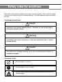
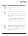
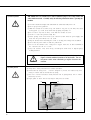
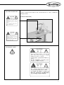
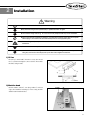
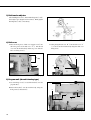
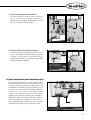
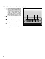
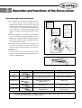
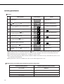
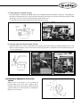
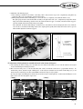
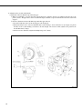
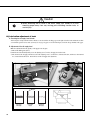
USER’S
MANUAL
KM-1060BL Series
KM-1060BL
KM-1060BL-7
KM-1062BL
KM-1062BL-7
lity
a
u
tQ
Besst Pricevice
Be st Ser
Be
1. Thank you for purchasing our product. Based on the rich expertise and
experience accumulated in industrial sewing machine production, SUNSTAR
will manufacture industrial sewing machines, which deliver more diverse
functions, high performance, powerful operation, enhanced durability, and
more sophisticated design to meet a number of user’s needs.
2. Please read this user’s manual thoroughly before using the machine. Make
sure to properly use the machine to enjoy its full performance.
3. The specifications of the machine are subject to change, aimed to enhance
product performance, without prior notice.
4. This product is designed, manufactured, and sold as an industrial sewing
machine. It should not be used for other than industrial purpose.
R
Safety rules for machines
1. Specifications
1) Sewing machine
2) Motor
3) Peripheral automation devices (optional)
2. Installation
1) Oil fan
2) Machine head
3) Belt tension adjuster
4) Belt cover
5) Program unit (thread trimming type)
6) Air pressure-related parts and functions (thread trimming type)
7) Thread spool stand assembly
8) Knee-lifting pad (thread non-trimming type)
9) Lubrication check
10) Check for stop position of the sewing machine (thread trimming type)
11) Back tack button (thread trimming type)
12) Check for switch functions (thread trimming type)
3. Operation and functions of the Servo motor
1) Operation and control of the pedal
2) Setting potentiometer
4. Control and adjustment of the sewing machine
1) Inserting a needle
2) Inserting/separating a bobbin
3) Winding lower thread
4) Routing upper thread
5) Thread tension adjustment
6) Adjustment of the stitch length
7) Adjustment of lifting amount of main and auxiliary presser foot
8) Pressure adjustment of the presser foot
9) Timing adjustment of needle and feed dog
10) Height adjustment of feed dog
11) Timing adjustment of needle and hook
12) Clearance adjustment of hook and opener
13) Position adjustment of hook needle guard
14) Height adjustment of the auxiliary presser foot
15) Timing adjustment of main auxiliary presser foot and needle
16) Adjustment of the thread trimming device
17) Adjustment of the thread tension release
18) Lubrication adjustment of hook
19) Replacement of the gauge
5. Cause of troubles and troubleshooting
1) Sewing machine troubleshooting
6. Table drawing
Safety rules for machines
Safety labels in the manual are categorized into danger, warning and caution. Failure to follow the safety
rules may result in physical injuries or mechanical damages. The safety labels and symbols are defined
as follows.
The meaning of the safety marks
Danger
Instructions here shall be observed strictly. Otherwise, the user will be killed or
suffer severe physical injuries.
Warning
Instructions here must be observed, or the user could suffer fatal or severe
physical injuries.
Caution
Instructions here should be observed, or the user could face physical injuries or
mechanical damages.
The meaning of marks
This mark means a must-not
This mark means a must for safety
This mark means that an electric shock may be caused if the instruction is not
followed properly.
4
1-1) Machine mobilization
Only personnel with a full understanding of the safety rules should move the machines.
The following directions must be observed when delivering the machines.
Danger
1-2) Machine installation
Physical damages such as functional difficulties or breakdowns may occur depending on
installation conditions of the machines. Be sure to heed the following conditions.
Caution
[Note] Details of the machine installation are laid out in No. 2 Installation.
1-3) Troubleshooting
When the machine is in need of repair, only our authorized service technicians must
handle it.
Danger
5
1-4) Machine operation
KM-1060BL Series are intended to be used for industrial purposes for sewing textiles and
other similar materials. Carefully study the following instructions before operating the
machine.
Warning
Caution
1-5) Safety device
Warning
6
Always start the machine with safety covers in place since
fingers or hands could be injured or cut off by the belt. Turn off
the power switch when conducting a regular check on the
machine.
1-6) Location of caution mark
Caution is attached on the machine for safety. Read the directions of caution carefully before
running the machine.
[Location of caution mark]
1-7) Contents of caution
7
1
Specifications
1) Sewing machine
Description
Application
Maximum stitch length
Stroke distance of needle bar
Lifting amount of presser foot
Needle type
Hook type
Reverse sewing
Feeding device
Lubrication
Specifications of bed
Power supply
KM-1060BL-7 (trimming type)
KM-1060BL
KM-1062BL (Trimming type)
Medium heavy to very heavy material
9mm
33.8mm
Maximum of 7 mm
DP x 17 #22 (#14~#25)
Horizontal hook
Reverse button & lever
Reverse lever
Reverse button & lever
Total feeding (needle, feed dog, upper feed presser foot)
Automatic oil supply
568 x 178 mm (working space of 300 mm)
1 phase 110/220 V
3 phase 220V
Reverse lever
1 phase 110V/220V
3 phase 220V
1 phase 110/220V
3 phase 220V/380V
KM-1062BL
1 phase 110/220V
3 phase 220V/380V
Sewing speed
Description
Lifting amount of the main and sub presser foot
Sewing speed
1
2
3
4
1.0 mm~2.4 mm
2.5mm 3.9mm
4.0mm 4.7mm
4.8mm 7.0mm
3500spm
3000spm
2500spm
2000spm
Note)
1. The sewing speed automatically changes by the default value of the lifting amount of the main and sub presser foot (trimming type)
2. When using the stitch length longer than 6mm, set the sewing speed at under 2,000 spm in the program unit box.
3. Since automatic speed control is not available for non-trimming types, the sewing speed must be controlled manually at the value shown in the table
above. When using the stitch length longer than 6mm, be sure to set the sewing speed at under 2,000 spm to avoid mechanical damages.
2) Motor
Model
S3M55-1B
S3M55-2B
S3M55-3B
Voltage
Single Phase 110V
Single Phase 220V
Triple Phase 220V
Watt
550 W
550 W
550 W
Hertz
50/60 Hz
50/60 Hz
50/60 Hz
Model
Voltage
110V / 220V
220V / 380V
Watt
400W
400W
Hertz
50/60Hz
50/60Hz
3) Peripheral automation devices (optional)
Name
Model
Use
Application
Production Counter
SCOUN-1
A counting device which indicates the completed quantity
on the program unit panel, including added, subtracted,
corrected or remaining quantity along with other
performance rates.
Basic type PU
Material edge sensor
SEDG-1
SEDG-2
A device that senses the edge or thickness of the sewing
material to stop the machine without manual pedaling.
Available in two types: SEDG-1 for edge sensing type and
SEDG-2 for thickness sensing type.
Basic type PU
SPDL-1
SPDL-2
A device needed when only one operator runs several
sewing machines. Pedals for acceleration, thread trimming,
presser foot and ascending are built separately. Two types,
SPDL-1 and EDPL1 for fixed speed type and SPDL-2 and
EDPL-2 for adjustable speed type are available.
Basic Type PU/
Option Type PU
Standing pedal
8
Servo Motor
470 Motor
2
Installation
Warning
The machine must be installed by a trained technician only.
Any electrical wiring must be performed by a qualified technician or agent.
The machines weigh over 52 kg. As such, two or more people should carry out the installation.
Plug in only after the installation is complete. If the operator mistakenly steps down on the pedal
with the plug in, the machine will start automatically and can cause physical injuries.
Connect the ground (earth) wire. An unstable connection may result in an electric shock or a
malfunction.
Place the belt cover on top of the machine
Use both hands when bending the machine backward or returning it to the normal position.
Using only one hand can lead to physical injuries due to the weight of the machine.
1) Oil fan
Fix oil tray and oil tank from the accessory box onto oil
fan as shown in the Figure 1, then secure the oil fan under
the table using six nails.
[ Fig. 1 ]
2) Machine head
Nail the rubber cushion onto hinge rubber and four
edges, then install the head hinge in the sewing machine
with the head inserted in the bed.
[ Fig. 2 ]
9
3) Belt tension adjuster
After installing the motor , slacken both fixing nuts and
just enough to give adequate tension to belt . Firmly tighten
the fixing nuts and consecutively.
[ Fig. 3 ]
4) Belt cover
A. Insert the head groove of belt cover support screw into
the lower grooves of the belt cover A . Fix the belt
cover onto the machine body and the top cover with two
belt cover fixing screws .
B. After placing the belt cover B
into the belt cover A
, secure it onto the machine body using three belt cover
fixing screws.
[ Fig. 4 ]
[ Fig. 5 ]
5) Program unit (thread trimming type)
A. Use four fixing screws
program unit .
to attach the bracket
onto the
B. Fasten the bracket onto the machine body, using two
fixing screws and washers .
[ Fig. 6 ]
10
Caution
When it becomes necessary to regulate the machine with the power on or with the air injected,
exercise extreme caution for safety.
Set the air pressure at 0.5 Mpa.
6) Air pressure-related parts and functions (thread trimming type)
A. Installation
a) Use a screw to fix the pneumatic unit onto the lower side of the table as illustrated in the Fig.
b) Connect five pneumatic tubes from right to left as shown in the Fig. Tie the tube with other lead lines using band clip .
[ Fig. 7 ]
Label mark
Cylinder
Function
S1P
Conversion cylinder of
lifting amount of presser foot
Converts the lifting amount of the main and auxiliary
presser foot to the maximum 7 mm in an instant
S2P
Reverse sewing cylinder
S3L
S3R
Automatic presser foot-lifting cylinder
Raises the presser foot to as high as 16 mm off the
surface of needle plate
Conversion cylinder for stitch length
Performs sewing in accordance with the settings of the
lower stitch length dial when this particular cylinder
begins to run among two stitch length dials of the
machine
S5S
Performs reverse sewing
11
B. Adjustment of pneumatic pressure
a. Adjust the pressure by pulling knob from pneumatic
filter .
b. Control the pneumatic pressure at 0.49 MPa (5kgf/cm )
and put the knob back to its original position..
[ Fig. 8 ]
7) Thread spool stand assembly
Secure the thread spool stand assembly
washer and nut on the right side.
onto the table using
[ Fig. 9 ]
8) Knee-lifting pad (thread non-trimming type)
A. Place the socket of the knee-lifting pad (ass y) from the
accessory box into the knee-lifting shaft .
B. Loosen the bolt to set a position comfortable for knee
lifting and then re-tighten it.
[Caution]
Take out the knee-lifting pad (ass y) before pushing
the machine backward.
[ Fig. 10 ]
12
Caution
Plug in only after oil supply is finished. If the operator mistakenly steps on the pedal with the
plug in, the machine will start automatically and can cause severe injuries.
When handling lubricants, wear protective glasses or gloves to avoid contact with your eyes or
skin. Inflammation may be caused otherwise. Never drink lubricants since they can cause
vomiting or diarrhea. Keep it out of the reach of children
Operate the machine only after adding oil when the machine is being used for the first time or
has been left unused for a long time.
9) Lubrication check
A. Bed part
Loosen oil cap screw to fill up the oil tank to the gauge
line of the oil gauge . Afterwards, tighten the screw
firmly.
[ Fig. 11 ]
B. Face plate
Dismantle the facet by unfastening two fixing screws of the
facet and add the sewing machine oil into an arrow
position. Reassemble the facet afterwards.
[ Fig. 12 ]
13
C. Hook part
Open the slide plate (right) to add the sewing machine
oil into an arrow-pointed position. Close the slide plate
after oiling.
[ Fig. 13 ]
D. Oil window check
After applying oil to each friction parts, turn on the main
switch and operate the machine at a low speed for five
minutes to check the oil flow in the oil hose passing the oil
window. The oil flow can be checked after about one
minute of machine operation. To ensure the machine is
maintained in an excellent condition, run the machine at
2,000 spm/minute for the first 4~5 days and at a normal
speed afterwards.
[ Fig. 14 ]
10) Check for stop position of the sewing
machine (thread trimming type)
Check for the machine stop position after moving the needle
up and down by pushing the reverse button . See if the sign
B is shown on the window of the belt cover when the
needle stops in an up position. If not, adjust the position of the
magnetic holder embedded in the pulley, for trimming
function can be adversely affected when the position is not
adequate.
[ Fig. 15 ]
14
A. Check for up-stop position of needle bar
The up-stop position of needle bar is where the take-up
lever stops 2mm off of its highest position. For
adjustment, move the magnetic holder built in a carved
N.U. sign of the pulley to the left and right.
[ Fig. 16 ]
B. Check for down-stop position of needle bar
The down-stop position of needle bar is where the carved
sign of the needle bar coincides with the tip of the needle
bar frame . If the position is not suitable, move the
magnetic holder built in a carved N.D. sign of the pulley
to the left and right for adjustment.
[ Fig. 17 ]
11) Back tack button (thread trimming type)
Pressing the back tack button or reverse button during
forward sewing will start reverse sewing immediately. When
you stop the machine and restart it by stepping down on the
pedal with the reverse button already pressed down, you can
perform reverse sewing from the beginning. When the
machine is in a stop mode, you can change up-down
position of the needle bar by pressing the reverse button.
Lightly pressing the button once will stop the needle bar in a
high position. Pressing the reverse button twice within less
than a second will stop the needle bar in a low position. In
short, the button delivers two functions: one for reverse sewing
and the other for converting vertical position of the needle.
[ Fig. 18 ]
15
12) Check for switch functions (thread trimming type)
: Conversion switch for presser foot lifting level
- When you press this switch, the light will come on.
The lifting amount of the presser foot will
automatically change to the maximum 7 mm
regardless of what the set-up data is in the top
cover dial. When you press the switch back, the
light will go off and the sewing machine will run at
the setting value as displayed in the top cover dial.
: Automatic back tack (B/T) selection switch
- This switch is designed to select Insert/Delete of
the start and end of B/T sewing.
: Switch for stopping needle bar at high position
- designed to raise the needle bar to the highest
position regardless of the stop position of the
sewing machine
: Conversion switch for the stitch length
- While this switch is on, the machine will run at
the setting value of the lower dial and when off,
the machine will operate at the setting value of
the upper dial.
16
Fig. 19
3
Operation and functions of the Servo motor
1) Operation and control of the pedal
A. Loosen fixing nut and turn pressure-adjusting screw
in a clockwise direction as shown in Figure 20. The
machine will start running at a backward step 1. The pedal
will become heavier when the automatic presser foot is
raised. Likewise, the pedal will become lighter when the
screw is shifted in a counterclockwise position. After
adjusting the weight of the pedal, firmly tighten the fixing
nut .
B. Unfasten the fixing nut and turn the pressure-adjusting
screw clockwise, then the machine will begin to run at a
backward step 2. The pedal will become heavier when the
trimming device begins to operate, and lighter when the
screw is turned counterclockwise.
C. In adjusting the pedal pressure while sewing forward,
secure the tension spring onto the left side groove to
decrease pressure and onto the right side groove to increase
pressure.
D. Pedal operation
You can perform various functions with the sewing
machine by moving the pedal (foothold) forward and
backward as illustrated below.
Function
Pedal position
Fig. 20
Peal operation
Sewing machine operation
Low-speed
operation
When pedal is pressed down at forward step 1
Machine rotates at a low speed
High-speed
operation
When pedal is pressed down to
the maximum in forward position
Machine rotates at a high speed
Neutral position
When pedal is not pressed down
(Original position)
Machine stops
Presser foot lift
When pedal is pressed down
at backward step 1
Presser foot is lifted
Trimming operation
When pedal is pressed down
at backward step 2
Trimming device starts running
and cuts the thread
For more detailed information on operation and functions of the Servo motor, please refer to our manual
Fortuna Ac Servo Motor Series III provided by SunStar.
17
2) Setting potentiometer
How to set
How to operate
Sequence
Screen display
Details
1
Turn on the power
2
Press
3
Press
4
Turn the dial for adjusting presser foot lifting amount and set it
at 2.5 (mm)
When dial is turned, the value will be displayed
on
5
Set at 2.5 (mm) and press the
button. The screen will
automatically change with a buzzer sound
P2 setting screen for Group A item 27
6
Turn the dial again to set at 4.0 (mm)
When dial is turned, the value will appear
on
7
Set at 4.0 (mm) and press
button. The screen will
automatically change with a buzzer sound
P3 setting screen for group A item 27
8
Turn the dial once again to set at 4.8 (mm)
When dial is turned, the value will be displayed
on
9
Set at 4.8 (mm) and press
with a buzzer sound
button to change the screen
Setting is complete
10
After setting is complete, push
initial screen
button to go back to the
Sewing initial screen
Sewing initial screen
button, then press
button to change screen
and
button while holding down
Initial screen for parameter group A
button to move to parameter number 27
P1 setting screen for group A item 27
When setting each step of P1, P2 and P3, be sure to press
button to save the set value. Otherwise, the set value will not be saved.
The sign from screen 3 to 8 in the above table may vary to some degree depending on the location of the installed potentiometer.
If you turn off the power before completing step 9, you will have to start over again.
The set value of the potentiometer will be erased if you initialize. Initialize only when it is necessary. Remember that you have to reset
the potentiometer after initialization.
If the potentiometer connector is not linked or the cable is cut, OV will be displayed on the screen.
Relation between presser foot lifting amount and maximum speed of the sewing machine
18
Presser foot lifting amount
Maximum speed of the sewing machine
1.0 - 2.5 mm
3500 spm
2.5 - 4.0 mm
3000 spm
4.0 - 4.8 mm
2500 spm
4.8 - 7.0 mm
2000 spm (adjustable from group A item 20)
4
Control and adjustment of the sewing machine
Caution
Always turn off the power when mounting a needle. If the operator mistakenly steps on the
pedal while the power is on, the machine will start automatically and can result in physical
injuries.
When using clutch motor, be aware that the motor will continue to rotate for a while even after
the power is switched off due to inertia. Start to work on the sewing machine only after the
motor has come to a complete stop.
1) Inserting a needle
With the needle groove facing left as shown in the [Figure
21], insert the needle tip into the upper end of stopper hole
and fasten the needle with clamp screw .
[ Fig. 21 ]
2) Inserting/separating a bobbin
A. How to separate
Hold the needle at the highest position. Press the slide
plate stopper, open the slide plate and hold up the bobbin
case holder of hook to take out the bobbin .
[ Fig. 22 ]
B. How to insert
IInsert thread-winded bobbin into the bobbin case .
Pull the lower thread out by dropping it through the thread
path and the bottom of the shaft tension spring plate .
Let the lower thread hang about 50 mm. Place back the
bobbin by referring to How to separate, starting from end
to beginning.
[ Fig. 23 ]
19
3) Winding lower thread
A. How to wind the lower thread
a) Turn the thread from the backside of the tension
adjusting plate to the front through the hole .
b) Bring the thread towards the bobbin and wind it 5~6
times in a clockwise direction, starting from the bottom up.
c) Push the lever to make the pulley touch the V-belt
and start the machine
d) When the lower thread is winded up completely on the
bobbin, the pulley will automatically separate from
the V-belt.
e) The adequate quantity of lower thread winding is
about 80%.
[ Fig. 24 ]
B. Winding adjustment for lower thread
a) If the lower thread winds irregularly, loosen the screw to move it left and right. Fasten it back after adjustment.
b) Winding quantity of the lower thread can be adjusted by turning the adjusting screw . Move the screw clockwise for more
quantity and counterclockwise for less quantity.
c) As for adjusting the tension of the lower thread winded on the bobbin, turn the nut clockwise direction to increase the tension and
counterclockwise to reduce the tension.
Caution
Turn off the power switch when routing the upper thread. If the operator mistakenly presses
down on the pedal while switched on, the machine will start automatically and can cause
physical injuries.
When using the clutch motor, be aware that the motor will continue to rotate for a while after the
power is switched off. Start to work on the sewing machine only after the motor has come to a
complete stop.
4) Routing upper thread
After placing the take-up lever in its highest position, hang the upper thread as shown in the figure.
-For initial sewing, the suitable length of the upper thread tail from the needle hole is about 50 mm.
[ Fig. 25 ]
20
Caution
Turn off the power when adjusting the lower thread tension. If the operator mistakenly steps
down on the pedal while switched on, the machine will start automatically and can cause
physical injuries.
When using the clutch motor, be aware that the motor will continue to rotate for a while after the
power is switched off. Start to work only after the motor has come to a complete stop.
5) Thread tension adjustment
A. Tension adjustment of the lower thread
If you turn screw on the spring plate mounted in hook
in a clockwise direction, the lower thread tension will
become stronger and when turned in a counterclockwise
direction, weaker.
strong
Weak
[ Fig. 26 ]
B. Tension adjustment of the upper thread
a. Tension adjustment of thread-adjusting device
(for 1060 BL type)
As shown in [Figure 27], tension will become heavier
when tension-adjusting nut of the thread-adjusting
device is turned clockwise, and lighter when turned
counterclockwise.
Weak
Strong
[ Fig. 27 ]
b. Tension adjustment of thread-adjusting device
(for 1062 BL type)
As indicated in [Figure 28], tension of the left thread will
become stronger when tension-adjusting nut of the
thread-adjusting device is turned clockwise, and weaker
when turned counterclockwise. If you turn the tensionadjusting nut clockwise, tension of the right thread will
become stronger, and weaker when turned counterclockwise.
Strong
Weak
[ Fig. 28 ]
21
c) Adjustment of the take-up lever spring
If you loosen the stopper clamp screw and turn the take-up lever spring stopper counterclockwise as shown in [Figure 29], the
moving range of the take-up lever spring will become larger, and when turned clockwise, smaller.
The standard moving range of the take-up lever spring is 5~10 mm.
[ Fig. 29 ]
d) Tension adjustment of the take-up lever spring
If you unfasten the nut in the thread-adjusting device shaft and turn it clockwise at the face groove of the thread-adjusting device
shaft using a screwdriver, the tension of the take-up lever spring will become stronger, and weaker when turned counterclockwise.
e) Timing adjustment of the take-up lever spring
If you loosen the stopper screw and move the guide plate of the take-up lever spring in a clockwise direction, the operating timing
of the take-up lever spring will become faster, and slower when turned counterclockwise.
The standard operating timing of the take-up lever spring is when the stopper screw comes to position at the center of the guide plate .
Weak
Strong
[ Fig. 30 ]
22
[ Fig. 31 ]
f) Tension adjustment of the auxiliary thread adjustment device
(for 1060 BL)
If you turn the adjusting nut of the auxiliary thread-adjusting
device as displayed in [Figure 32] in a clockwise direction, the
needle will have a shorter length thread left after trimming, and
a longer length thread left when turned in a counterclockwise
direction. 50~60 mm is the most appropriate length of the
upper thread tail left in the needle after trimming.
g) Tension adjustment of auxiliary thread adjustment device
(for 1062 BL)
As illustrated in [Figure 33], you can adjust the remaining
length of the upper thread in the needle after trimming by
controlling the adjusting nut of the auxiliary thread-adjusting
device
(left , right )
Weak
Strong
[ Fig. 32 ]
Weak
Strong
[ Fig. 33 ]
6) Adjustment of the stitch length
Adjusting dial and designed to control the stitch length can
be set up with two different lengths, and change the stitch length
whenever switch is pressed down. After pressing down switch
to turn the switch on, the sewing machine will carry out sewing
at the stitch length as set on dial . When pressing down switch
again to turn the switch off, the machine will start sewing at the
stitch length as set on dial . Set the desired stitch length to a
carved sign .
[ Fig. 34 ]
Caution
The value set on the stitch length dial should always be smaller than that of dial . Nonetheless, if
you force turning the dial to set the value of dial to be greater than that of dial , the machine can be
severely damaged.
The function of the stitch length dial
is installed for non-trimming types.
is available only for trimming type machines. Stitch length dial
23
7) Adjustment of lifting amount of the main and auxiliary presser foot
The lifting level of the main presser foot and auxiliary presser foot can be adjusted from 1 to 7 mm by the upper lid dial . If you
turn the upper lid dial around to a carved sign so that the figure on the dial faces the carved sign, the main presser foot and
auxiliary presser foot will start a mutual crossing movement as much as the set figure indicates. For trimming types only, when the light
comes on by pressing the switch on the arm, the mutual crossing movement will change to the maximum value of 7 mm regardless of
the set value indicated on the dial . When the light goes off by repressing the switch, the movement will change automatically to the set
value on the dial. .
Operates at the setting value of dial
[ Fig. 35 ]
[ Fig. 36 ]
8) Pressure adjustment of the presser foot
If you turn the dial on the upper part of the faceplate in a clockwise direction, the pressure of the auxiliary presser foot will increase, and
decrease if turned counterclockwise.
Strong
Weak
[ Fig. 37 ]
24
Caution
After disassembling and adjusting a safety device, always place it back to the original position and
check whether it functions as intended.
Use both hands when pushing the machine backward or returning it to the original position.
Due to the weight of the machine, your hand can get stuck in the machine if you should slip.
When adjusting the machine with the switch on, be sure to pay extreme caution.
Only trained engineers must perform troubleshooting or inspection of the machine.
For electrical repair or inspection, consult with qualified technicians or agent.
9) Timing adjustment of needle and feed dog
Set the stitch length to the maximum and place the thread take-up lever in the highest position. (As a standard, a carved sign C will
appear on the belt cover window and the feed dog will rise to touch the surface of needle plate . The needle tip will move down to
touch the needle plate .) If the position is not correct, make the adjustment as indicated in the following.
A. Disassemble the bed cover.
B. Loosen the fixing screw of the lower feed cam to control the position of the feed dog and fasten the screw firmly afterwards.
Normally, the No. 1 screw of the lower feed cam faces the centerline of the lower feed cam connecting rod when the needle
bar is in the highest position.
[ Fig. 38 ]
25
10) Height adjustment of feed dog
Set the stitch length to a minimum and put the feed dog in the highest position. The needle bar will come down to the lowest position and
the feed dog must be raised 0.5 mm off of the needle plate. If the position is not suitable, make the height adjustment as indicated below.
A. Disassemble the bed cover
B. Unfasten the fixing screw of the lower feed cam , adjust the position and fasten back the screw tightly.
Normally, a carved sign of the lower feed cam heads up perpendicularly with the needle bar in its lowest position.
[ Fig. 39 ]
[ Fig. 40 ]
11) Timing adjustment of needle and hook
Set the stitch length to a minimum and place the needle 2 mm off of the lowest position. A carved sign H will appear on the belt cover
window and hook tip will come to the center of the needle. The appropriate clearance between the needle groove and the shaft tip
is 0.02~0.1 mm. At this time, the needle guard of the hook must not come in contact with the needle.
[ Fig. 41 ]
26
A. Timing adjustment of needle and hook
Set the stitch length to a minimum for 1060 BL and to 6 mm for 1062 BL, and then disassemble the needle plate. After pushing back
the machine, loosen the fixing screw of the lower shaft collar and place the needle to ascend 2 mm off of the lowest position. Adjust
the hook tip to come to the center of the needle and firmly fasten the fixing screw .
At this time, the clearance between the hook tip and the needle eye is 1.4 mm.
[ Fig. 42 ]
[ Fig. 43 ]
B. Clearance adjustment between needle and hook
Unfasten the fixing screw and of the hook base and control the position of the hook base by turning the adjusting collar of the
hook base to the left and right. Set the clearance between the hook tip and needle at around 0.02~0.1 mm and tighten the fixing screw
and of the hook base.
[ Fig. 44 ]
12) Clearance adjustment of hook and
opener
Bring the opener to the hook as close as possible and
loosen the fixing screw of the opener. Adjust the opener
manually to allow 0.5~0.7 mm of clearance between the hook
stopper and the groove of the needle plate , and tighten the
fixing screw of the opener.
[ Fig. 45 ]
27
13) Position adjustment of hook needle guard
After moving the needle bar to the lowest position, check if the needle touches the needle guard by about 0.1~0.2 mm. For
adjustment, turn the fixing screw of the needle guard in a clockwise direction to push the needle guard away from the needle, and
turn it counterclockwise to pull the needle guard closer to the needle.
[ Fig. 46 ]
14) Height adjustment of the auxiliary presser foot
Normally the auxiliary presser foot lifts 9 mm off the needle plate when the pressure bar lifter is raised.
A. Raise the pressure bar lifter , unfasten the pressure-adjusting screw and bring up the auxiliary presser foot 9 mm off the surface
of the needle plate.
B. Loosen the fixing screw of the pin attached onto the pressure bar lifter bracket .
C. Move the pin close to the bracket towards the arrow direction and fasten the fixing screw securely afterwards.
[ Fig. 47 ]
28
15) Timing adjustment of the main auxiliary presser foot and needle
A. Adjustment of maximum ascending amount of the
main auxiliary presser foot
The maximum lifting quantity of the main and auxiliary presser
foot is 7 mm. First, set the upper lid dial at 1 and take out
the upper lid. Move the body of a climb device towards the
arrow direction until it reaches the stopper plate . At this
time, set the clearance between the outer round of the pin
head, which is inserted into crank and outer round of the
screw at 45.5 mm. Tighten the crank clamp screw . After
adjustment, reassemble the upper lid with the dial set at 1 .
[ Fig. 48 ]
B. Adjustment of lifting amount of the main auxiliary
presser foot
The height of lifting amount of the main auxiliary presser
foot must be equal. Make the adjustment as indicated below.
a) Set the stitch length at a maximum.
b) Take out the rubber cap from the upper lid.
c) Loosen the clamp screw and turn the machine until the
needle tip and the upper part of the feed dog come to meet
on the surface of the needle plate.
d) Adjust the crank to make sure that the main and
auxiliary presser foot touch the needle plate at the same
time and fasten the clamp screw .
e) After adjustment, place back the rubber cap on the upper lid.
[ Fig. 49 ]
C. Timing adjustment of the main auxiliary presser foot and needle
As a standard, the needle tip enters the needle hole of the feed dog immediately after the main presser foot touches the feed dog.
Likewise, the main presser foot comes apart from the feed dog right after the needle tip comes out of the feed dog. Refer to the
following for adjustments.
a) Disassemble the upper lid with the dial set at 1 .
b) Loosen two fixing screws of vertical movement cam of the presser foot.
c) After securing the needle bar in the highest position, hold the No.1 screw of the cam so that it faces up perpendicularly.
Afterwards, tighten the cam-fixing screws.
d) Place back the upper lid after adjustment.
[ Fig. 50 ]
29
16) Adjustment of the thread trimming device
A. Adjustment of the trimmer driving part
a) Fixing the position of the trimmer solenoid (ass y)
After assembling the solenoid bracket in the trimmer base , tighten the solenoid using a clamp screw .
When the whole body of the trimmer base (in unit) is assembled - with the solenoid shaft assembled onto the clutch lever in a
position where the trimmer shaft and trimmer shaft collar return to after having completed the trimming action, the solenoid
stroke must be assembled at 8.5 mm.
When the assembling is finished, check if the solenoid shaft returns quickly and smoothly to the original position when released
from the arrow direction. If not, readjust the solenoid shaft by unfastening the clamp screw .
[ Fig. 51 ]
b) Fixing the position of the trimming cam
Turn the pulley manually to place the take-up lever about 1~2 mm off of the lowest position.
Adjust the position of the cam to allow the trimmer cam roller to smoothly enter the cam (Bring the stopper collar to the
right side of the cam )
Tighten firmly three fixing screws of the trimmer cam. Turn the pulley manually to check if the machine runs smoothly.
[ Fig. 52 ]
30
c) Adjustment of the trimming stopper
After trimming is finished for the trimmer cam leading, roller must enter the range of the complementary straight line by
rotating the pulley to place the trimming cam in the right position.
While pressing down the trimmer shake linkage to move the roller to completely come inside the trimmer cam ,
- The right equal point of the roller should adhere smoothly to the right inside of the cam s complementary straight line and the
left tip of the trimmer shake linkage should as well come inside the trimmer stopper smoothly. Adjust the trimmer stopper
to the left and right and fasten the holder clamp screws tightly.
- After adjustment, the trimmer shake linkage should not move when shaken to the left and right (the roller is now inside the
cam). Be sure to check if the shake linkage returns to the original position quickly and smoothly when released. If not, proceed
with horizontal adjustment of trimmer stopper .
Complementary
straight line
Movement finishing
point of movable knife
Movement starting
point of movable knife
Line of trimming cam
[ Fig. 53 ]
B. Adjustment of linking device for movable knife shaft in the trimmer driving part
a) After adjusting the trimmer driving part as described above, the trimmer shake linkage (ass y) must be returned to the original
location after finishing the trimming movement.
b) First, loosen the fixing screw of the movable knife shaft crank and hold the crank down to a perpendicular direction. To
maintain this position, adjust the length of linking bar of the ball joint assembled onto the trimmer shake linkage (ass y) and
firmly fasten the crank-fixing screw. (For model 1062BL, unfasten the clamp screw together)
(To change the length of the linking bar of the ball joint, loosen the left nut and the right nut , and then turn the linking bar. A nut
(left) is a left screw and a nut (right) is a right screw)
[ Fig. 54 ]
31
C. Adjustment of the movable and fixed knife
a) Adjustment of the movable knife-edge and hook stopper
When a movable knife passes the front side of the hook stopper , limit the clearance to be within 0.7~0.8 mm range as the
picture shows. The upper surface of the movable knife-edge should be set up 0.35~0.45mm below the lower side of hook
stopper .
Clearance adjustment of the movable knife-edge and hook stopper front side
Loosen the needle plate and secure the hook stopper on the needle plate
Unfasten the fixing screw of the movable knife shaft eccentric bushing . Insert a thin driver or any adequate size pin into
the hole of the eccentric bushing and turn it to the left and right. The clearance will be adjusted as the position of the
movable knife shaft changes.
After the clearance adjustment, retighten the bushing fixing screw firmly.
[ Fig. 55 ]
32
b) Adjustment of the movable knife and fixed blade
The standard initial assembling position of the movable knife is where the movable knife-edge protrudes 1.0~1.2 mm from the
edge of the fixed blade .
Adhesive condition of the fixed blade and movable knife has a large bearing on trimming functions of the machine. Refer to
the below picture for checking the surface adhesion.
[Checking the surface adhesion of the movable and fixed blades]
Start manual trimming operation after painting marking ink on the upper part of the movable knife . You can check the adhesion of
the movable and fixed blades by checking the ink trace left on the surface of the movable knife. If adhesion is not acceptable, turn
the pressure-adjusting screw of the fixed blade support to the left and right for pressure adjustment.
Caution) Forcefully turning the pressure-adjusting screw
in a clockwise direction can break the fixed blade.
[Checking surface (facet) adhesion]
-
Coat marking ink on the upper tip of
the movable blade.
(Good)
(Bad) Turn the pressure-adjusting
screw of the fixed blade holder
in a clockwise direction for
adjustment, and double-check
adhesion status.
(Bad) Turn the pressure-adjusting screw
of the fixed blade holder in a
counter-clockwise direction for
adjustment, and double-check the
adhesion status.
[ Fig. 56 ]
33
c) Adjustment of the lower thread holder
The whole side of the lower thread holder must adhere to
the lower side of the movable blade . Also the lower
thread holder tip should be positioned 2.5~3.0 mm
inwards off the tip of the movable blade . For adjustment,
unfasten the fixing screw of the holder and retighten
afterwards.
[ Fig. 57 ]
D. Checklist for assembly of other trimming devices
a) Checking the operation starting point of the movable
blade during trimming when the movable blade begins
to move by manual trimming operation, check whether
the take-up lever is sitting on the lowest point or 2.5 mm
above the lowest point.
[ Fig. 58 ]
b) Maintaining the fixed blade
Check the condition of the movable knife tip if thread
does not break easily during operation or if the thread tip
is untidy. When the blade tip is dull, use sand paper or
oil grindstone to sharpen the edges.
SAND PARER
OIL GRINDSTONE
[ Fig. 59 ]
34
17) Adjustment of the thread tension release
The standard opening level of thread tension-adjusting disc is 0.8~1.0 mm. Adjust the tray as described below.
A. Disassemble the upper lid with the dial set at 1 .
B. Push down the pressure bar lifter to lower the presser foot
C. Press the solenoid plate towards the arrow direction
D. After loosening nut , turn the cam nut around and check if the tray opens to a width of 0.8 ~1.0 mm. Then securely tighten the
nut .
E. Reassemble the upper lid after adjustment.
[ Fig. 60 ]
35
Caution
When checking the oil level in the hook, keep your hands or oil flow
checking paper away from any moving parts including transfer tools, to
avoid injury.
18) Lubrication adjustment of hook
A. Checking the oil supply level of hook
After racing the sewing machine for three minutes, secure the oil flow checking paper on the right side of the hook and run the machine
at a maximum speed for ten seconds. (You may use any type of paper) As shown in the figure, check the oil tape marked on the paper.
B. Adjustment of the oil supply level
Make the adjustment when the quantity of oil supply is not adequate.
a) Take off the sliding plate (left) .
b) Turn the machine manually until you see the adjusting screw for the oil supply level of the hook.
c) The amount of the oil supply will decrease when the adjusting screw is turned in a clockwise direction, and increase when turned
in a counterclockwise direction. Check the level of the oil supply after adjustment.
Oil Tape
Excessive
Oil supply
Proper Oil
supply
Insufficient
Oil supply
[ Fig. 61 ]
36
19) Replacement of the gauge
A. Refer to the gauges shown in the SunStar Parts Manual when ordering a gauge for replacement.
B. Take out the gauge parts
originally attached to the machine.
C. Unfasten clamp screws and as illustrated in [Figure 63].
Fig. 62
Fig. 63
D. Loosen four fixing screws on the left and right of the hook base as shown in [Figure 64]
E. Mount the new feed dog and needle plate.
F. Insert the needle plate into the groove of the needle bar as explained in [Figure 65] and fasten the clamp screw .
Fig. 64
Fig. 65
G. Refer to the previous instruction for setting each gauge.
Caution
Only qualified and trained technicians should change the gauge.
Before replacing, always turn off the power switch and pull the power plug. If the operator
mistakenly steps on the pedal with the switch on, the machine will start automatically and can cause
injury.
When using a clutch motor, be aware that the motor will continue to rotate for a while even after
the power is off due to inertia. Proceed to work after the motor has come to a complete stop.
For gauge parts replacement, use parts specified by SunStar.
37
5
Cause of troubles and troubleshooting
1) Sewing machine troubleshooting
No
Symptom
Checkpoints
Root cause
Corrective action
Direction and height of needle
Needle is inserted into wrong position
Reinsert the needle correctly
Needle
Needle is bent
Change the needle
Bad timing of feed dog
Adjust the timing of feed dog
Ascending level of needle bar
Bad timing of needle and hook
Adjust the timing of needle and hook
Height of needle
Bad timing of needle and hook
Adjust the timing of needle and hook
Gap between needle and hook
Bad timing of needle and hook
Adjust the timing of needle and hook
Threading method
Wrong threading
Thread the needle correctly
Needle
Bent needle or broken needle tip
Change the needle
Direction and height of needle
Needle inserted in the wrong position
Insert the needle correctly
Upper thread tension
Too tight upper thread tension
Reduce tension of upper thread
Lower thread tension
Too loose lower thread tension
Reduce tension of lower thread
Working capacity of take-up lever spring
Loose upper thread
Adjust take-up lever spring
Direction and height of needle
Needle inserted into wrong position
Reinsert the needle in the right direction
Needle
Bent needle or broken needle tip
Change the needle
Threading
Thread passing at wrong position
Change the needle
Ascending level of needle bar
Wrong timing of needle and hook
Adjust the timing of needle and hook
Height of needle bar
Wrong timing of needle and hook
Adjust the timing of needle and hook
Gap between needle and hook Wrong timing of needle and hook
Adjust the timing of needle and hook
Needle breaks
Thread breaks
Stitch skips
Remaining length of upper thread is short
Adjust the thread adjusting device
Racing-proof spring of Due to bobbin racing during trimming, lower
bobbin case
thread dropping from bobbin case becomes Change the racing protection spring
too short to go up
Take-up lever spring
38
Unable to lift lower thread due to weak take- Adjust the working capacity of take-up lever
up lever spring
spring
No
Condition
Checking Point
Cause of Trouble
Troubleshooting
Upper thread is
not sunk
Too tight upper thread tension
Reduce tension of upper thread
Too loose lower thread tension
Increase tension of lower thread
Lower thread is
not sunk
Too weak upper thread tension
Increase tension of upper thread
Too strong lower thread tension
Decrease tension of lower thread
Tension of fixed blade
Tension not aligned between movable and fixed blade
Adjust tension of movable and fixed blade
Edge of movable and fixed blades
Abrasion in blade groove of movable and fixed blade
Replace movable and fixed blade
Direction of needle
Wrong needle insertion
Reinsert the needle correctly
Insufficient crossing quantity of movable
and fixed blade
Adjust the stroke of movable and fixed
blade
Too strong upper thread tension
Adjust tension of upper thread
Too thick a needle for thread
Check thickness of needle
Take-up lever pulls out the upper
thread because the needle up and
down position is too high
Adjust the up-stop position of
needle
Trimming errors
Crossing of trimmer cam
notch mark and blade
Upper thread is
pulled out when
sewing
commences
Up-stop position of
needle
39
6
40
Table drawing