1
Cat.No. M066–E1–1
H8GN
Preset Counter/Timer
USER’S MANUAL
H8GN
Preface
The H8GN supports serial communications specifications, CompoWay/F and Sysway.
This User's Manual describes the communications functions of the H8GN.
Before using your H8GN thoroughly read and understand this manual in order to
ensure correct use.
Also, store this manual in a safe place so that it can be retrieved whenever necessary.
E OMRON, 2000
All rights reserved. No part of this publication may be reproduced, stored in a retrieval system or transmitted,
in any form, or by any means, mechanical, electronic, photocopying, recording, or otherwise, without the prior
written permission of OMRON.
No patent liability is assumed with respect to the use of the information contained herein. Moreover, because
OMRON is constantly striving to improve its high-quality products, the information contained in this manual is
subject to change without notice. Every precaution has been taken in the preparation of this manual. Nevertheless, OMRON assumes no responsibility for errors or omissions. Neither is any liability assumed for damages
resulting from the use of the information contained in this publication.
I
H8GN
PRECAUTIONS
When the product is used under the circumstances or environments described in this
manual always adhere to the limitations of the rating and functions. Also, for safety,
take countermeasures such as fitting failĆsafe installations.
DO NOT USE:
• In circumstances or environments that have not been described in this manual.
• For control in nuclear power, railway, aircraft, vehicle, incinerator, medical, enterĆ
tainment, or safety applications
• Where death or serious property damage may occur, or where extensive safety preĆ
cautions are required.
II
H8GN
SAFETY PRECAUTIONS
JSafety Signal Words
This manual uses the following signal words to mark safety precautions for the H8GN.
These precautions provide important information for the safe application of the product. You
must be sure to follow the instructions provided in all safety precautions.
CAUTION
Indicates information that, if not heeded, could result in relatively serious or
minor injury, damage to the product, or faulty operation.
JSafety Precautions
CAUTION
F Electric Shock Warning
Tighten the terminal screws properly. Loose screws may cause ignition and malfunction.
Tightening torque :0.5 Nm max.
Do not operate this product in flammable and explosive gas atmospheres.
The life expectancy of the output relays varies greatly with the switching capacity and other switching
conditions. Always use the output relays within their rated load and electrical life expectancy. If an outĆ
put relay is used beyond its life expectancy, its contacts may become fused or burned.
Never disassemble, repair or modify the product.
Doing so may cause electric shock, fire or malfunction.
Do not allow metal fragments or lead wire scraps to fall inside this products.
These may cause leak of electricity, fire or malfunction.
III
H8GN
NOTICE
Be sure to observe these precautions to ensure safe use.
(1) When storing the H8GN, make sure that the ambient temperature and humidity are within the
rated values. Leave the H8GN at room temperature for at least three hours before using the H8GN
if it has been stored at an ambient temperature of Ć10_C or below.
(2) Do not use the H8GN in the following locations.
Ă• Locations with excessive vibration or shock.
Ă• Locations where the H8GN is exposed to sprayed water or oil.
(3) Do not use the H8GN in dusty environments or expose it to corrosive gases or direct sunlight.
(4) Be sure to use the H8GN according to its rated ambient operating temperature and humidity
ranges.
(5) Make sure that the voltage is applied within the specified range. Otherwise the internal elements
of the H8GN may be damaged.
(6) When using the H8GN in an area with excess electronic noise, separate the H8GN, wiring, and the
equipment which generates the input signals as far as possible from the noise sources. It is also
recommended to shield the input signal wiring to prevent electronic interference.
(7) If the H8GN is used in locations with high static electricity, such as sites with pipes transporting
molding materials, powders, or liquids, be sure to separate the H8GN from all sources generating
static electricity.
(8) Organic solvents (such as paint thinner), as well as very acidic or basic solutions can damage the
outer casing of the H8GN.
IV
H8GN
NOTICE
(1) Do not use the H8GN in the following locations:
Ă• Locations with high humidity that may result in condensation
Ă• Locations with radical temperature changes
(2) Pay the utmost attention not to make mistakes in polarity when wiring the Timer.
(3) Always maintain the power supply voltage within the specifications.
(4) Connect the power supply voltage through a relay or switch in such a way that the voltage reaches
a fixed value at once. Otherwise, the H8GN may not be reset or outputs may turn ON.
(5) Be sure that the capacity of the power supply is large enough, otherwise the H8GN may not start
due to inrush current (Approx. 15A) that may flow for an instant when the H8GN is turned on.
(6) For the power supply of an input device for the H8GN, use an isolating transformer with the primaĆ
ry and secondary windings mutually isolated and the secondary winding not grounded.
(7) Leaving the H8GN with outputs ON at a high temperature for a long time may hasten the degradaĆ
tion of internal parts (such as electrolytic capacitors). For this reason, by using in combination
with relays, avoid situations where outputs are left ON for a long time (e.g. one month or more).
(8) If the watertight rubber packing is not compressed sufficiently, water may penetrate the panel. For
this reason, be sure to tighten the reinforcement screws of the Mounting Adapter (Y92FĆ34).
(9) The output contacts are SPSTĆNO and SPSTĆNC. For this reason, be sure not to use these contacts
in circuits that will result in 3Ćpoint shortĆcircuits (power supply shortĆcircuiting due to arcing).
(10) In counter operation:
Ă• Changing the set value
When changing the set value during operation, the output will turn ON if the set value equals
the present value.
Ă• Operation with set value and present value of 0
The output will turn ON if the set value of 0 equals the present value. The output will be OFF
while the Reset Key is pressed or the reset input is ON.
(11) In timer operation:
Ă• Changing the set value
When changing the set value during operation, the H8GN operates in the same way as when the
present value reached the set value because a constant readĆin system is in use. And output may
turn ON depending on the output mode if the set value is changed as follows:
Input mode UP:
Input mode DOWN:
Present value y Set value
Elapsed time y Set value (Present value=0)
Note: When in DOWN mode, the amount set value is changed is added to or subtracted from
the present value.
Ă• Operation with set value of 0
a)
When the output mode is set to A, B (oneĆshot output), D, or F, output will turn ON when
the start signal is input.
b)
When the output mode is set to B (hold output), E, or Z, output will remain OFF even when
the start signal is input.
V
H8GN
(12) To allow for the startup time of peripheral devices (sensors, etc.), the H8GN starts timing operaĆ
tion between 210 to 260 ms after power is turned ON. For this reason, in operations where timing
starts from power ON, the time display will actually start from 258 ms. If the set value is 258 ms
or less, the time until output turns ON will be a fixed value between 210 and 260. (Normal operaĆ
tion is possible for set value of 259 ms or more.) In applications where a set value of 258 ms or less
is required, use start timing with signal input.
VI
H8GN
Table of Contents
Preface . . . . . . . . . . . . . . . . . . . . . . . . . . . . . . . . . . . . . .
Precautions . . . . . . . . . . . . . . . . . . . . . . . . . . . . . . . . . .
Safety Precautions . . . . . . . . . . . . . . . . . . . . . . . . . . . .
Notice . . . . . . . . . . . . . . . . . . . . . . . . . . . . . . . . . . . . . . .
Notice . . . . . . . . . . . . . . . . . . . . . . . . . . . . . . . . . . . . . . .
CHAPTER 1 ABOUT COMMUNICATIONS METHODS . . . . . .
1-1
This chapter briefly describes the supported communications methods and how
to wire equipment. First-time users should read this chapter without fail to ensure
proper installation of the equipment.
1.1 Outline . . . . . . . . . . . . . . . . . . . . . . . . . . . . . . . . . . . . . . . . . . . . . . . . .
1-2
Introduction . . . . . . . . . . . . . . . . . . . . . . . . . . . . . . . . . . . . . . . . . . . . . . . . . . . . . . . .
Communications specifications . . . . . . . . . . . . . . . . . . . . . . . . . . . . . . . . . . . . . . . .
Transmission procedure . . . . . . . . . . . . . . . . . . . . . . . . . . . . . . . . . . . . . . . . . . . . . .
Interface . . . . . . . . . . . . . . . . . . . . . . . . . . . . . . . . . . . . . . . . . . . . . . . . . . . . . . . . . . .
Wiring . . . . . . . . . . . . . . . . . . . . . . . . . . . . . . . . . . . . . . . . . . . . . . . . . . . . . . . . . . . . .
Communications parameters . . . . . . . . . . . . . . . . . . . . . . . . . . . . . . . . . . . . . . . . .
1-2
1-2
1-3
1-3
1-3
1-4
CHAPTER 2 COMPOWAY/F COMMUNICATIONS
PROCEDURES . . . . . . . . . . . . . . . . . . . . . . . . . . . .
2-1
Read this chapter if you are to communicate using the CompoWay/F format.
2.1 Data Format . . . . . . . . . . . . . . . . . . . . . . . . . . . . . . . . . . . . . . . . . . . .
2-2
Command frame . . . . . . . . . . . . . . . . . . . . . . . . . . . . . . . . . . . . . . . . . . . . . . . . . . . .
Response frame . . . . . . . . . . . . . . . . . . . . . . . . . . . . . . . . . . . . . . . . . . . . . . . . . . . .
Communications data . . . . . . . . . . . . . . . . . . . . . . . . . . . . . . . . . . . . . . . . . . . . . . . .
Example of end code . . . . . . . . . . . . . . . . . . . . . . . . . . . . . . . . . . . . . . . . . . . . . . . .
2-2
2-3
2-4
2-4
2.2 Structure of Command Text . . . . . . . . . . . . . . . . . . . . . . . . . . . . . . .
2-5
PDU structure . . . . . . . . . . . . . . . . . . . . . . . . . . . . . . . . . . . . . . . . . . . . . . . . . . . . . .
Area definitions . . . . . . . . . . . . . . . . . . . . . . . . . . . . . . . . . . . . . . . . . . . . . . . . . . . . .
Type code (variable type) . . . . . . . . . . . . . . . . . . . . . . . . . . . . . . . . . . . . . . . . . . . .
Addresses . . . . . . . . . . . . . . . . . . . . . . . . . . . . . . . . . . . . . . . . . . . . . . . . . . . . . . . . .
Number of elements . . . . . . . . . . . . . . . . . . . . . . . . . . . . . . . . . . . . . . . . . . . . . . . . .
List of services . . . . . . . . . . . . . . . . . . . . . . . . . . . . . . . . . . . . . . . . . . . . . . . . . . . . . .
2-5
2-5
2-5
2-5
2-5
2-6
2.3 Details of Services . . . . . . . . . . . . . . . . . . . . . . . . . . . . . . . . . . . . . . .
2-7
Read from variable area . . . . . . . . . . . . . . . . . . . . . . . . . . . . . . . . . . . . . . . . . . . . .
Write to variable area . . . . . . . . . . . . . . . . . . . . . . . . . . . . . . . . . . . . . . . . . . . . . . . .
Read controller attributes . . . . . . . . . . . . . . . . . . . . . . . . . . . . . . . . . . . . . . . . . . . . .
Read controller status . . . . . . . . . . . . . . . . . . . . . . . . . . . . . . . . . . . . . . . . . . . . . . .
Echoback test . . . . . . . . . . . . . . . . . . . . . . . . . . . . . . . . . . . . . . . . . . . . . . . . . . . . . .
Operation instructions . . . . . . . . . . . . . . . . . . . . . . . . . . . . . . . . . . . . . . . . . . . . . . .
2-7
2-8
2-10
2-11
2-12
2-13
2.4 Response Code List . . . . . . . . . . . . . . . . . . . . . . . . . . . . . . . . . . . . .
2-15
I
II
III
IV
V
H8GN
CHAPTER 3 COMMUNICATIONS DATA . . . . . . . . . . . . . . . . . .
3-1
This chapter lists the details of each of the communications data in the CompoWay/F communications procedures.
3.1 Variable Area (setup range) List . . . . . . . . . . . . . . . . . . . . . . . . . . .
3.2 Status . . . . . . . . . . . . . . . . . . . . . . . . . . . . . . . . . . . . . . . . . . . . . . . . . .
3.3 Sample Program . . . . . . . . . . . . . . . . . . . . . . . . . . . . . . . . . . . . . . . .
3-2
3-6
3-9
APPENDIX . . . . . . . . . . . . . . . . . . . . . . . . . . . . . . . . . . . . . . . . . . . . .
A-1
ASCII List . . . . . . . . . . . . . . . . . . . . . . . . . . . . . . . . . . . . . . . . . . . . . . . . . . .
A-2
INDEX
CHAPTER 1 ABOUT COMMUNICATIONS METHODS
1
CHAPTER 1
ABOUT
COMMUNICATIONS
METHODS
This chapter briefly describes the supported communications methods
and how to wire equipment. FirstĆtime users should read this chapter
without fail to ensure proper installation of the equipment.
1.1 Outline . . . . . . . . . . . . . . . . . . . . . . . . . . . . . . .
1Ć2
Introduction . . . . . . . . . . . . . . . . . . . . . . . . . . .
1Ć2
Communications specifications . . . . . . . . . .
1Ć2
Transmission procedure . . . . . . . . . . . . . . . .
1Ć3
Interface . . . . . . . . . . . . . . . . . . . . . . . . . . . . . .
1Ć3
Wiring . . . . . . . . . . . . . . . . . . . . . . . . . . . . . . . .
1Ć3
Communications parameters . . . . . . . . . . . .
1Ć4
1–1
H8GN
CHAPTER 1 30P aaaaaaa
1.1 Outline
JIntroduction
The program for the communications functions are created on the host
computer, and the H8GN's parameters are monitored or set from the host
computer. Therefore, the description provided here is from the viewpoint
of the host computer.
CompoWay/F is OMRON's standard communications format for general
serial communications. This format uses a standard frame format as well
as the FINS* commands which have proven successful in OMRON's PLCs.
Therefore, it can simplify communications between components and the
host computer.
* FINS (Factory Interface Network Service)
The FINS protocol provides message communications between controlĆ
lers in OMRON FA networks.
The H8GN have the following communications functions:
Ă• Reading/writing of parameters
Ă• Operation instructions
Ă• Selection of setup levels
Communications are subject to the following condition:
Ă• Parameters can be written only when the communications writing"
parameter is set to ON (enabled).
JCommunications specifications
Transmission line connection
Multiple point
Communications method
RS-485 (2-wire, half-duplex)
Synchronization method
Start-stop synchronization
Baud rate *1
1200, 2400, 4800, 9600 (bit /s)
Communication code
ASCII
Data bits
*1
7 or 8 bits
Stop bits
*1
1 or 2 bits
Error detection
Vertical parity (non, even, or odd)
BCC (block check character)
Flow control
None
Interface
RS-485
Retry function
None
Communications buffer
40 byte
*1 Baud rate, data bits, stop bits and vertical parity can each be set indeĆ
pendently in the communications setting level. Highlighted characters
in the table above indicate defaults.
1–2
H8GN
JTransmission
procedure
When the host computer transmits a command frame, the H8GN transĆ
mits a response frame that corresponds to the command frame. A single
response frame is returned for each command frame. The following diaĆ
gram shows the operation of the command and response frames.
Command frame
Command frame
Host computer
H8GN
Response frame
Allow a wait time of at least 2 ms until the next command is sent after the
host computer receives a response from the H8GN.
JInterface
Communications with the host computer are carried out through a stanĆ
dard RSĆ485 interface.
JWiring
Ă• RSĆ485 connections can be 1 : 1 or 1 : N. A maximum of 32 Units (including
the host computer) can be connected in oneĆtoĆN systems.
Ă• The total cable length is 500 m max.
Ă• Use a shielded, twistedĆpair cable AWG28 or larger for wiring the H8GN.
Communications transceiver
Host computer
RS-485
Abbr
FG
–
+
SG
H8GN
RS-485
Pin No.
8
7
TX
Abbr
A(–)
B(+)
RX
6.8V
Shielded cable
A<B: [1] mark
A>B: [0] space
Both ends of the transmission line
(including the host computer) must be
specified (by setting terminator ON) as
the end node. The total resistance of
the terminators must be at least 54Ω.
Terminator H8GN
120Ω
end node
(1/2W) RS-485
Pin No. Abbr
8
A(–)
7
B(+)
Shielded cable
Use a terminator of resistance
120Ω = (1/2W).
Match the communications specifications of the H8GN and the host comĆ
puter. If a oneĆtoĆN system is being used, be sure that the communications
specifications of all devices in the system (except individual unit numbers)
are the same.
1–3
H8GN
JCommunications
parameters
The H8GNs communications specifications are set in the communications
setting level. These parameters are set on the H8GNs front panel.
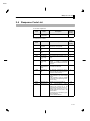
The following table shows the communications parameters and their setĆ
ting ranges.
Parameter
Displayed
Characters
Setting Range
Set Value
Communications unit No.
0 to 99
0, 1 to 99
Baud rate
1.2 / 2.4 / 4.8 / 9.6 (k bit/s)
1.2 / 2.4 / 4.8 / 9.6 (k bit/s)
Communications data length
7 / 8 (bit)
7 / 8 (bit)
Communications stop bit
1/2
1/2
Communications parity
None / even / odd
/
/
Highlighted characters indicate defaults.
F Communications
parameter setup
Before you carry out communications with the H8GN, set up communicaĆ
tions unit No., Communication rate and other parameters by carrying out
the following procedure.
(1) Hold down the
key for at least three seconds to move from the
operation level" to the initial setting level."
(2) Press the
key for less than one second to move from the initial
setting level" to the communications setting level."
key.
(3) Select the parameters as shown below by pressing the
(4) Use the
or
keys to change the parameter set values.
Communications unit No.
Baud rate
Communications data length
Communications stop bit
Communications parity
H8GN
1–4
H8GN
F Communications
parameter setup
Note that communications parameters are enabled after they have been
changed by resetting the controller.
Ă• Communications unit No. (
)
This parameter is for setting the unit No. to each of the H8GN. This unit
No. is set so that the host computer can identify the H8GN when commuĆ
nications are carried out with the host computer. Set a unit No. within
the range 0 to 99 for each H8GN connected to the host computer on the
network. Default is 1". When two or more H8GN are used, do not set
the same unit No. Doing so will prevent normal operation.
Ă• Baud rate (
)
This parameter is for setting the baud rate when communicating with
the host computer. Set one of 1.2 (1200 bit/s)", 2.4 (2400 bit/s)", 4.8
(4800 bit/s)" and 9.6 (9600 bit/s)".
Ă• Communications data length (
)
This parameter is for setting the communications data length. Set either
of 7 bits" or 8 bits".
)
Ă• Communications stop bit (
This parameter is for setting the communications stop bit. Set either of
1" or 2".
Ă• Communications parity (
)
This parameter is for setting the communications parity. Set one of
none", even" or odd".
1–5
H8GN
1–6
CHAPTER 2 CompoWay/F COMMUNICATIONS PROCEDURES
2
CHAPTER 2
CompoWay/F
COMMUNICATIONS
PROCEDURES
Read this chapter if you are to communicate using the CompoWay/F
format.
2.1 Data Format . . . . . . . . . . . . . . . . . . . . . . . . . . .
2Ć2
Command frame . . . . . . . . . . . . . . . . . . . . . . .
2Ć2
Response frame . . . . . . . . . . . . . . . . . . . . . . . .
2Ć3
Communications data . . . . . . . . . . . . . . . . . .
2Ć4
Example of end code . . . . . . . . . . . . . . . . . . . .
2Ć4
2.2 Structure of Command Text . . . . . . . . . . . . .
2Ć5
PDU structure . . . . . . . . . . . . . . . . . . . . . . . . .
2Ć5
Area definitions . . . . . . . . . . . . . . . . . . . . . . . .
2Ć5
Type code (variable type) . . . . . . . . . . . . . . .
2Ć5
Addresses . . . . . . . . . . . . . . . . . . . . . . . . . . . . .
2Ć5
Number of elements . . . . . . . . . . . . . . . . . . . .
2Ć5
List of services . . . . . . . . . . . . . . . . . . . . . . . . .
2Ć6
2.3 Details of Services . . . . . . . . . . . . . . . . . . . . . .
2Ć7
Read from variable area . . . . . . . . . . . . . . . .
2Ć7
Write to variable area . . . . . . . . . . . . . . . . . . .
2Ć8
Read controller attributes . . . . . . . . . . . . . . .
2Ć10
Read controller status . . . . . . . . . . . . . . . . . .
2Ć11
Echoback test . . . . . . . . . . . . . . . . . . . . . . . . . .
2Ć12
Operation instructions . . . . . . . . . . . . . . . . . .
2Ć13
2.4 Response Code List . . . . . . . . . . . . . . . . . . . .
2Ć15
2–1
H8GN
CHAPTER 2 CompoWay/F COMMUNICATIONS PROCEDURES
2.1 Data Format
Unless otherwise indicated, numbers in this manual are expressed in hexĆ
adecimal. Values in double quotation marks, such as 00", are ASCII.
The number underneath each delimiter in a frame indicates the number
of bytes.
JCommand frame
Text
Node No.
STX
1
2
Sub-address
0
0
2
SID
0
Command text
1
BCC calculation range
BCC
ETX
1
1
STX
This code (02) indicates the beginning of the communications frame (text).
Always set this character in the first byte.
When STX is received again during reception, reception is carried out again from
the point where STX was received.
Node number
•
•
•
•
Sub-address
This is not used on the H8GN. Be sure to set the sub-address to “00”.
SID (service ID)
This is not used on the H8GN. Be sure to set the sub-address to “00”.
Command text
Command text area. For details, see “2.2 Structure of Command Text.”
ETX
This code (03) indicates the end of the text.
BCC
Block Check Character
The BCC result is found by calculating the exclusive OR of the bytes from the node
No. up to ETX.
2–2
This number specifies the transmission’s destination.
Specify the H8GN’s “Communications unit No.”.
BCD range “00” to “99” and “XX” can be set.
Specify “XX” for a broadcast transmission. No response will be returned for broadcast transmissions.
• No responses will be returned from node Nos. set otherwise from the above.
H8GN
Data
2.1 Format
F BCC calculation
example
STX
The BCC is formed by converting the 8Ćbit value obtained by converting
the exclusive OR of the node No. up to ETX into two ASCII characters, and
setting this to the BCC area.
Node No.
02H
Sub-address
SID
Command text
0(30H) 0(30H) 0(30H) 0(30H) 0(30H) 0(30H) 5(35H) 0(30H) 3(33H)
ETX
BCC
03H
35H
BCC=30H30H30H30H30H30H35H30H33H03H=35H
Calculation result 35H is set to the BCC area.
The symbol indicates exclusive OR operation and the H indicates hexadecimal code.
JResponse frame
Node No.
Sub-address
End code
Command text
STX
1
End
code
BCC
ETX
2
2
Name
2
1
Description
1
Error
Detection
Priority
00
Normal completion
The command ended normally without error.
None
0F
FINS command error
The specified FINS command could not be executed.
The FINS response code should indicate why the command
could not be executed.
8
10
Parity error
The sum total of bits whose received data is “1” does not
match the set value of “communications parity.”
2
11
Framing error
Stop bit is “0”.
1
12
Overrun error
An attempt was made to transfer new data when the reception data was already full.
3
13
BCC error
The calculated BCC value is different from the received BCC
value.
5
14
Format error
• The command text contains characters other than 0 to 9,
and A to F. This error is not applicable to the echoback test.
(For details, see chapters 2.3 “Echoback test.”)
• No SID and command text. Or, no command text
• “MRC/SRC” not included in command text
7
16
Sub-address error
• Illegal (unsupported) sub-address
• No sub-address, SID and command text
• Sub-address less than two characters, and no SID and
command text
6
18
Frame length error
The received frame exceeds the fixed (supported) number of
bytes.
4
Ă• The end code is returned to received command frames addresses to the
self node.
Ă• No response will be returned if all the items in the response frame are
incomplete up to the ETX and BCC.
Ă• Error Detection Priority" indicates the priority when two or more
errors occur simultaneously.
2–3
H8GN
CHAPTER 2 CompoWay/F COMMUNICATIONS PROCEDURES
JCommunications data
Set (monitor) Value
Minus Value
Decimal point
8 digits (Hex)
2’s complement
Decimal point is removed and the result is converted to hexadecimal.
Example) 105.0 ! 1050 ! 000041A
JExample of end
code
The following examples show an end code when a command did not end
normally.
Example 1) Illegal subĆaddress, and no SID and command text
Command Format
Node No.
STX
BCC
Sub-address
0
A
ETX
Response Format
Node No.
STX
Sub-address
0
A
BCC
End code
1
6
ETX
End code is 16" (subĆaddress error).
This is because a subĆaddress was received and the subĆaddress
error has a higher error detection priority than the format error.
Example 2) No command text
Command Format
Node No.
STX
Sub-address
0
0
SID
0
BCC
ETX
Response Format
Node No.
STX
Sub-address
0
0
BCC
End code
1
4
ETX
End code is 14" (format error).
Example 3) All node Nos. not provided
Command Format
BCC
STX
ETX
The node No. is lacking one character.
Response Format
No response
Example 4) No subĆaddress, and illegal BCC
Command Format
BCC
Node No.
STX
ETX
Err
Response Format
Node No.
STX
Sub-address
0
0
BCC
End code
1
3
ETX
SubĆaddress is 00" and end code is 13" (BCC error).
2–4
H8GN
Structure
2.2
of Command Text
2.2 Structure of Command Text
JPDU structure
An MRC (Main Request Code) and SRC (SubĆRequest Code) followed by
the various required data is transferred to the command text.
Service request PDU
MRC
SRC
Data
MRES (Main Response Code) and SRES (SubĆResponse Code) are
transferred following the above MRC/SRC. Data is then transferred
following these MRES and SRES.
Service response PDU (during normal operation)
MRC
SRC
MRES
SRES
Data
If the specified command text could not be executed, only the MRC/
SRC and MRES/SRES become the target response PDUs.
Service response PDU (at non-execution of specified command text)
MRC
SRC
MRES
SRES
MRES/SRES becomes the response code except when processing
ends in normal completion."
JArea definitions
Areas comprise only variable area.
JType code
(variable type)
The following defines variable area type codes.
Variable
type
Description
C0
R/O (read only) parameter.
C1
Protect level parameter.
C2
Operation and adjustment level parameter.
C3
Initial setting, communications setting and advanced function setting level parameter.
JAddresses
Each of the variable types is appended with an address. Express addresses
in 2Ćbyte hexadecimal code.
JNumber of
elements
The number of elements is expressed in 2Ćbyte hexadecimal code. Specify
the number of elements within the range 0 to 2".
For example, when the number of elements is 0002", specify data for two
items from the address.
2–5
H8GN
CHAPTER 2 CompoWay/F COMMUNICATIONS PROCEDURES
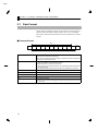
JList of services
MRC
SRC
Name of service
Process
01
01
Read from variable
area
This service reads from variable areas.
01
02
Write to variable area
This service writes to variable areas.
05
03
Read controller
attributes
This service reads the model No. and communications buffer size.
06
01
Read controller
status
This service reads the run status of the
controller.
08
01
Echoback test
This service carries out the echoback test.
30
05
Operation
instructions
This service carries out reset, communications writing, multi-SP, move to protect
level, move to setup area 1 and software
reset.
* In a memory error (RAM error) or initial state (until the control starts normaly after the
power is turned ON), all commands will not be accepted, and no response will be returned.
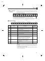
The following table summarizes setup areas 0 and 1.
2–6
Area
Description
Setup area 0
This area groups together the protect, operation and adjustment
levels.
Setup area 1
This area groups together the initial setting, communications setting and advanced function setting levels.
H8GN
Details
2.3
of Services
2.3 Details of Services
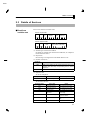
JRead from
variable area
This service reads from variable areas.
Service request PDU
MRC
SRC
0
0
1
2
Variable
type
Read start
address
2
4
Bit
position
1
0
2
Number of
elements
0
2
4
Service response PDU
MRC
SRC
0
0
1
2
Response
code
Read data
(for number of elements)
4
0 or 8 or 16
1
2
(1) Variable type and read start address
For details on variable types and read start addresses, see Chapter 3
Communications Data."
(2) Bit position
Bit accessing is not supported on the H8GN. Fixed to 00".
(3) Number of elements
Number of
elements
Process
0000
Read is not carried out (the service response PDU is not
appended with read data), and processing ends in “normal
completion.”
0001 to 0002
Read is carried out, and processing ends in “normal completion.”
(4) Response code
At normal completion
Response code
Name
Description
0000
Normal completion
No errors were found.
At occurrence of error
Response code
Error name
Cause
1001
Command too long
The command is too long.
1002
Command too short
The command is too short.
1101
Area type error
The variable type is wrong.
1103
Start address out-ofrange error
The read start address is
out of range.
110B
Response too long
The number of elements is
larger than “0002”.
1100
Parameter error
The bit position is other than
“00”.
2203
Operation error
CPU or EEPROM error
2–7
H8GN
CHAPTER 2 CompoWay/F COMMUNICATIONS PROCEDURES
JWrite to variable
area
This service writes to variable areas.
Service request PDU
MRC SRC
0
1
0
2
Variable
type
Read start
address
2
4
2
2
Bit
position
0
Number of
elements
Write data
(for number of elements)
4
0 or 8 or 16
0
2
Service response PDU
MRC SRC
0
1
2
0
Response
code
2
2
4
(1) Variable type and write start address
For details on variable types and write start addresses, see Chapter
3ăCommunications Data."
(2) Bit position
Bit accessing is not supported on the H8GN. Fixed to 00".
(3) Number of elements
2–8
Number of
elements
Process
0000
Write is not carried out (the service response PDU is not
appended with write data), and processing ends in “normal
completion.”
0001 to 0002
Write is carried out, and processing ends in “normal completion.”
H8GN
Details
2.3
of Services
(4) Response code
At normal completion
Response code
Name
Description
0000
Normal completion
No errors were found.
At occurrence of error
Response code
Error name
Cause
1002
Command too short
The command is too short.
1101
Area type error
Wrong variable type
1103
Start address out-ofrange error
Write start address is out of range.
1104
End address out-ofrange error
The write end address (write start
address + number of elements)
exceeds the final address of the variable area.
1003
Number of elements/
data mismatch
The number of data does not match
the number of elements.
1100
Parameter error
• Bit position is other than “00”.
• Write data is out of setting range.
3003
Read-only data
Variable type “C0” was written to.
2203
Operation error
• The “communications writing”
parameter is set to “OFF” (disabled).
• Writing was carried out on the
parameters from setup areas 0 to 1.
• Writing was carried out on a protected parameter other than in the
protect level.
• CPU or EEPROM error
2–9
H8GN
CHAPTER 2 CompoWay/F COMMUNICATIONS PROCEDURES
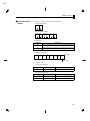
JRead controller
attributes
This service reads the model No. and communications buffer size.
Service request PDU
MRC SRC
0
5
0
2
3
2
Service response PDU
MRC SRC
0
5
2
0
Response
code
Model No.
4
10
3
2
Communications buffer size
0
0
2
8
4
(1) Model No.
The model No. is expressed in 10Ćbyte ASCII code. Empty bytes are
space codes.
Example:
The model number for the H8GN is expressed as follows:
H 8 G N – A D
(2) Communications buffer size
The communications buffer size is expressed in 2Ćbyte hexadecimal
code, and read after being converted to 4Ćbyte ASCII code.
Buffer size: 40 bytes (= H'0028)
(3) Response code
At normal completion
Response code
Name
Description
0000
Normal completion
No errors were found.
At occurrence of error
Response code
2–10
Name
Description
1001
Command too long
The command is too long.
2203
Operation error
CPU or EEPROM error
H8GN
Details
2.3
of Services
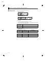
JRead controller
status
This service reads the run status of the controller.
Service request PDU
MRC SRC
0
6
0
2
1
2
Service response PDU
MRC SRC
0
6
0
2
Response
code
Run Related
status information
1
2
4
2
2
(1) Run status
Run status
Description
00
Status in which the count (timer) input can be accepted (error not
generated when setup area is 0)
01
Status in which the count (timer) input cannot be accepted (other
than above)
(2) Related information
7
6
5
4
3
2
1
0
0
0
0
0
0
0
0
Bit position
PV underflow
(3) Response code
At normal completion
Response code
Name
Description
0000
Normal completion
No errors were found.
At occurrence of error
Response code
Name
Description
1001
Command too long
The command is too long.
2203
Operation error
CPU or EEPROM error
2–11
H8GN
CHAPTER 2 CompoWay/F COMMUNICATIONS PROCEDURES
JEchoback test
This service carries out the echoback test.
Service request PDU
MRC SRC
0
8
0
2
Test data
1
2
0 to 23
Service response PDU
MRC SRC
0
8
0
2
Response
code
Test data
1
2
0 to 23
(1) Test data
Set any test data within the range 0" to 23".
Set a value for the test data within the ranges shown below according
to the communications data length.
Communications
data length
Test data
8 bits
20 to 7E, A1 to FE converted to ASCII code
7 bits
20 to 7E converted to ASCII code
(2) Response code
At normal completion
Response code
Name
Description
0000
Normal completion
No errors were found.
At occurrence of error
Response code
2–12
Name
Description
1001
Command too long
The command is too long.
2203
Operation error
CPU or EEPROM error
H8GN
Details
2.3
of Services
JOperation
instructions
This service carries out reset, communications writing, multiĆSP, move to
protect level, move to setup area 1 and software reset.
Service request PDU
MRC SRC
3
0
0
2
Instruction
code
Related
information
2
2
5
2
Service response PDU
MRC SRC
3
0
0
2
Response
code
5
2
4
(1) Instruction code and related information
Instruction
code
Description
Related information
00
Communications writing
00: OFF (disabled)
01: ON (enabled)
01
Reset
00: Reset PV
01: Reset totalizing count value
02: Reset PV/totalizing count value
02
SV-bank
00: Set value 0
01: Set value 1
02: Set value 2
03: Set value 3
06
Software reset *
00
07
Move to setup area 1
00
08
Move to protect level
00
* No response will be returned when a software reset is carried out.
(2) Response code
At normal completion
Response code
Name
Description
0000
Normal completion
No errors were found.
At occurrence of error
Response code
Error name
Cause
1001
Command too long
The command is too long.
1002
Command too short
The command is too short.
1100
Parameter error
Instruction code and related information are wrong.
2203
Operation error
• The “communications writing”
parameter is set to “OFF” (disabled). However, note that the error
is accepted regardless of the “communications writing” parameter setting (ON/OFF).
• The command cannot be processed. For details, see “(3)
Description of operating instructions and precautions” below.
• CPU or EEPROM error
2–13
H8GN
CHAPTER 2 CompoWay/F COMMUNICATIONS PROCEDURES
(3) Description of operation instructions and precautions
FĂCommunications writing
Set the communications writing" parameter to ON: enabled" or
OFF: disabled" according to related information. This instruction can
be accepted at both setup areas 0 and 1.
FĂReset
The PV and/or total count value is reset according to the related value.
[Reset PV]
Resets the PV." This can be accepted only in setup area 0. The operaĆ
tion error" occurs in the following instance:
Ă• When the reset is issued in setup area 1"
[Reset totalizing count value]
Resets the totalizing count value." This can be accepted only in setup
area 0. The operation error" occurs in the following instances:
Ă• When the reset is issued in setup area 1"
Ă• When select function" is set to timer"
Ă• When use total counter" is set to OFF"
[Reset PV/totalizing count value]
Resets the PV" and the totalizing count value." This can be accepted
only in setup area 0. The operation error" occurs in the following
instances:
Ă• When the reset is issued in setup area 1"
Ă• When select function" is set to timer"
Ă• When use total counter" is set to OFF"
FĂSVĆbank
Set four set value beforehand in the adjustment level so that you switch to
a desired set value. SVĆbank can be accepted at both setup areas 0 and 1.
The operation error" occurs in the following instance:
Ă• When use SVĆbank " is set to OFF"
FĂSoftware reset
This instruction resumes processing after the power is turned OFF.
This instruction can be accepted at both setup areas 0 and 1. No
response will be returned for this operation instruction.
FĂMove to setup area 1
This instruction moves to setup area 1" and can be accepted at both
setup areas 0 and 1. However, note that when initial setup/communicaĆ
tions protection" is set to 2", an operation error" is generated, and
move to setup area 1 is forbidden.
When this move is carried out from setup area 0, the display indicates
the select function" in the initial setting level." When this operation
instruction is issued in setup area 1, the display will not change.
FĂMove to protect level
This instruction moves to the protect level" and can be accepted only
in setup area 0. When this instruction command is issued in setup area
1, an operation error" is generated, and move to setup area 1 is forbidĆ
den.
2–14
H8GN
Response
2.4
Code List
2.4 Response Code List
At normal completion
Response
code
Name
Description
Error
detection
priority
0000
Normal
completion
No errors were found.
None
Description
Error
detection
priority
At occurrence of error
Response
code
Name
0401
Unsupported
command
The service function for the relevant
command is not supported.
1
1001
Command too
long
The command is too long.
2
1002
Command too
short
The command is too short.
3
1101
Area type error
The variable type is wrong.
4
1103
Start address
out-of-range
error
The read/write start address is out of
range.
5
1104
End address
out-of-range
error
The write end address (write start
address + number of elements)
exceeds the final address of the variable area.
6
1003
Number of elements/data mismatch
The number of data does not match
the number of elements.
7
110B
Response too
long
The response exceeds the communications buffer size (when larger than
number of elements 0002).
8
1100
Parameter error
• The bit position is other than “00”.
• The write data is out of the setting
range.
• The instruction code and related
information in the operating instruction is wrong.
9
3003
Read-only error
Variable type “C0” was written to.
10
2203
Operation error
• The
“communications writing”
parameter is set to “OFF” (disabled).
• Writing was carried out on the
parameters from setup areas 0 to 1.
• Writing was carried out on a protected parameter other than in the
protect level.
• Processing is not possible by operating instruction.
• CPU or EEPROM error
11
2–15
H8GN
CHAPTER 2 CompoWay/F COMMUNICATIONS PROCEDURES
2–16
CHAPTER 3 COMMUNICATIONS DATA
3
CHAPTER 3
COMMUNICATIONS
DATA
This chapter lists the details of each of the communications data in the
CompoWay/F communications procedures.
3.1 Variable Area (setup range) List . . . . . . . . .
3Ć2
3.2 Status . . . . . . . . . . . . . . . . . . . . . . . . . . . . . . . .
3Ć8
3.3 Sample Program . . . . . . . . . . . . . . . . . . . . . . .
3Ć9
N88Basic . . . . . . . . . . . . . . . . . . . . . . . . . . . . . .
3Ć9
Protocol macro . . . . . . . . . . . . . . . . . . . . . . . .
3Ć11
3–1
H8GN
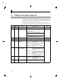
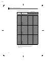
3.1 Variable Area (setup range) List
The following table lists the variable areas. Items expressed in hexadeciĆ
mal in the Set (monitor) Value" column are the setting range. Values in
parentheses ()" are the actual setting range.
For details of variable areas that are described not in numerical values but
by text, refer to the relevant parameter descriptions.
Variable Address
type
Item
Set (monitor) Value
C0
0000
Version * Note 1
H’00000100
C0
0001
PV
H’FFFFFC19 to H’0000270F (–999 to 9999)
Level
Operation
* Counter
* At PV underflow,
lower limit value=H’FFFFFC19 (–999)
H’00000000 to H’0000270F (0 to 9999)
* Time range at timer=other than - -m- -s, - -h- -m
H’00000000 to H’000026E7 (0:00 to 99:59)
* Time range at timer=- -m- -s, - -h- -m
C0
0002
Status * Note 1
See “3.2. Status.”
C0
0003
Totalizing count value
H’00000000 to H’05F5E0FF (0 to 99999999)
C1
0000
Operation/adjustment
protection
H’00000000 (0): No restrictions in operation and adjustment levels
H’00000001 (1): Move to adjustment level restricted
H’00000002 (2): Display and change of only PV/SV
parameters enabled
H’00000003 (3): Display of only PV/SV parameters
enabled
C1
0001
Initial setting/communications protection
H’00000000 (0): Move to initial setting/communications setting level enabled (move to
advanced function setting level displayed)
H’00000001 (1): Move to initial setting/communications setting level enabled (move to
advanced function setting level not
displayed)
H’00000002 (2): Move to initial setting/communications setting level restricted
C1
0002
Setting change protec- H’00000000 (0): OFF (changing of setup on controltion
ler display enabled)
H’00000001 (1): ON (changing of setup on controller
display disabled)
C1
0003
Reset key protection
3–2
H’00000000 (0): OFF (reset key enabled)
H’00000001 (1): ON (reset key disabled)
Operation
Protect
H8GN
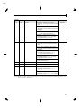
Variable Address
type
C2
0000
Item
Set value
Set (monitor) Value
H’00000000 to H’0000270F (0 to 9999)
Level
Operation
* Input mode at counter=incremental or decremental
H’FFFFFC19 to H’0000270F (–999 to 9999)
* Input mode at counter=individual or phase different input
H’00000000 to H’0000270F (0 to 9999)
* Time range at timer=other than - -m- -s,
- -h- -m and output mode=A,B,D,E,F
H’00000000 to H’000026E7 (0:00 to 99:59)
* Time range at timer=- -m- -s, - -h- -m and
output mode=A,B,D,E,F * Note 2
H’00000000 to H’00000064 (0 to 100)
* Output mode at timer=Z
C2
0001
Set value 0
H’00000000 to H’0000270F (0 to 9999)
Adjustment
* Input mode at counter=incremental or decremental
H’FFFFFC19 to H’0000270F (–999 to 9999)
* Input mode at counter=individual or phase different input
H’00000000 to H’0000270F (0 to 9999)
* Time range at timer=other than - -m- -s,
- -h- -m and output mode=A,B,D,E,F
H’00000000 to H’000026E7 (0:00 to 99:59)
* Time range at timer=- -m- -s, - -h- -m and
output mode=A,B,D,E,F * Note 2
H’00000000 to H’00000064 (0 to 100)
* Output mode at timer=Z
C2
0002
Set value 1
Same as set value 0
C2
0003
Set value 2
Same as set value 0
C2
0004
Set value 3
Same as set value 0
C2
0005
Cycle time
H’00000000 to H’0000270F (0 to 9999)
Operation
* Time range at timer=other than - -m- -s,
- -h- -m
H’00000000 to H’000026E7 (0:00 to 99:59)
* Time range at timer=- -m- -s, - -h- -m * Note 2
* Note 1: This item is not displayed on the controller display.
* Note 2: Even if the set value is within the setting range, the outĆofĆrange error occurs when the 2nd digit (sextal number) is six
or above such as 5:60 (H*00000230).
3–3
H8GN
CHAPTER 3 COMMUNICATIONS DATA
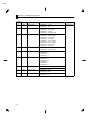
Variable Address
type
Item
Set (monitor) Value
C3
0000
Select function
H’00000000(0): Counter
H’00000001(1): Timer
C3
0001
Input mode
H’00000000(0):
H’00000001(1):
H’00000002(2):
H’00000003(3):
Incremental
Decremental
Individual
Phase difference
C3
0002
Time range
H’00000000(0):
H’00000001(1):
H’00000002(2):
H’00000003(3):
H’00000004(4):
H’00000005(5):
H’00000006(6):
H’00000007(7):
H’00000008(8):
0.000s to 9.999s
0.00s to 99.99s
0.0s to 999.9s
0s to 9999s
0m0s to 99m59s
0.0m to 999.9m
0h0m to 99h59m
0.0h to 999.9h
0h to 9999h
C3
0003
Timer mode
H’00000000(0): Elapsed time
H’00000001(1): Remainning time
C3
0004
Output mode (counter)
H’00000000(0):
H’00000001(1):
H’00000002(2):
H’00000003(3):
N
F
C
K
C3
0005
Output mode (timer)
H’00000000(0):
H’00000001(1):
H’00000002(2):
H’00000003(3):
H’00000004(4):
H’00000005(5):
A
B
D
E
F
Z
C3
0006
Output time
H’00000001 to H’0000270F (0.01 to 99.99) * counter
H’00000000 to H’0000270F (0.00 to 99.99) * timer
C3
0007
Counting speed
H’00000000(0): 30Hz
H’00000001(1): 5kHz
C3
0008
Input signal width
H’00000000(0): 20ms
H’00000001(1): 1ms
3–4
Level
Initial setting
H8GN
Variable
3.1
Area (setup range) List
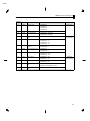
Variable Address
type
Item
Set (monitor) Value
C3
0009
Decimal point
H’00000000(0):
H’00000001(1):
H’00000002(2):
H’00000003(3):
---- - -.- -.- -.- - -
C3
000A
Pre-scale value
H’00000001 to H’0000270F (0.001 to 9.999)
C3
000B
Input signal edge
H’00000000(0): Rise edge
H’00000001(1): Fall edge
C3
000C
Communications unit
No. *1
H’00000000 to H’00000063 (0 to 99)
C3
000D
Baud rate *1
H’00000000(0):
H’00000001(1):
H’00000002(2):
H’00000003(3):
C3
000E
Communications data
length *1
H’00000007(7): 7
H’00000008(8): 8
C3
000F
Communications stop
bit *1
H’00000001(1): 1
H’00000002(2): 2
C3
0010
Communications parity H’00000000(0): None
H’00000001(1): Even
H’00000002(2): Odd
C3
0011
Use SV-bank
H’00000000(0): OFF
H’00000001(1): ON
C3
0012
Use totalizing counter
H’00000000(0): OFF
H’00000001(1): ON
C3
0013
Display auto-return
time
H’00000000(0): OFF
H’00000001 to H’00000063 (1 to 99)
C3
0014
Move-to-protect-level
time
H’00000003 to H’0000001E (3 to 30)
Level
Initial setting
Communications setting
1.2
2.4
4.8
9.6
Advanced
function setting
* 1: Communications parameters are enabled after they have been changed by turning the power OFF then back ON again.
3–5
H8GN
CHAPTER 3 COMMUNICATIONS DATA
3.2 Status
The figure below shows the structure of the status data:
15 14 13 12 11 10
0
0
0
0
0
9
8
7
0
0
0
6
5
4
3
2
1
0
0
0
0
Bit position
Spare
Spare
Spare
CP2 (gate) input
Reset input
Spare
Input status
CP1 (signal) input
Error info
PV underflow
Spare
Spare
Spare
Spare
Spare
Spare
Spare
3–6
Output status
Output
H8GN
Status
3.2
31 30 29 28 27 26 25 24 23 22 21 20 19 18 17 16
0
0
0
0
0
0
0
0
0
0
0
0
0
Bit position
0
Communications writing
Spare
Spare
Operating status
Setup area
Spare
Spare
Spare
Spare
Spare
Spare
Spare
Spare
Spare
Spare
Spare
Spare
3–7
H8GN
CHAPTER 3 COMMUNICATIONS DATA
The following shows the status contents.
Bit Description
Bit position
*
Status
0
1
Not generated
Generated
0
PV underflow *1
1
Spare
2
Spare
3
Spare
4
CP1 (signal) input *1
OFF
ON
5
CP2 (gate) input *1
OFF
ON
6
Reset input *1
OFF
ON
7
Spare
8
Spare
9
Spare
10
Spare
11
Spare
12
Output *1
OFF
ON
13
Spare
14
Spare
15
Spare
16
Setup area
Setup area 0
Setup area 1
17
Communications writing
OFF (disabled)
ON (enabled)
18
Spare
19
Spare
20
Spare
21
Spare
22
Spare
23
Spare
24
Spare
25
Spare
26
Spare
27
Spare
28
Spare
29
Spare
30
Spare
31
Spare
Spare" bits are OFF at all times.
*1: The status is as follows when reading is carried out in setup area 1:
@ PV underflow: Previous value is held until reset is generated.
@ CP1 (signal) input, CP2 (gate) input, reset input: OFF (0)
@ Output: OFF (0)
3–8
H8GN
Sample
3.3
Program
3.3 Sample Program
JN88Basic
The following sample program displays responses returned from the
H8GN on screen when command data is entered from the keyboard.
Enter starting with the unit up to the number of elements as the command
data.
This sample program was created using N88BASIC
1000
1010
1020
1030
1040
1050
1060
1070
1080
1090
1100
1110
1120
1130
1140
1150
1160
1170
1180
1190
1200
1210
1220
1230
1240
1250
1260
1270
1280
1290
1300
1310
1320
1330
1340
1350
1360
1370
1380
1390
1400
1410
1420
1430
’------------------------------------------------------’PROGRAM: H8GN Communication Sample Program (Compo Way/F)
’VERSION: 1.00
’(c) Copyright OMRON Corporation 2000
’All Right Reserved
’------------------------------------------------------’
’= Communications port setting (PARITY=EVEN, DATA=7, STOP=2)=”
’
OPEN ”COM: E73” AS #1
’
*REPEAT
’
’=====Transmission processing==========
’
’---------- Entry of send data ---------INPUT ”SEND DATA:”, SEND$
’
’---------- To exit processing if there is no entry ---------IF SEND$=”” THEN * EXIT
’
’---------- Calculation of BCC ---------BCC=0
SEND$=SEND$+CHR$ (3)
FOR I=1 TO LEN (SEND$)
BCC=BCC XOR ASC (MID$ (SEND$, I, 1))
NEXT I
BCC$=CHR$ (BCC)
’
’---------- Transmission ---------SDATA$=CHR$ (2)+SEND$+BCC$
PRINT #1, SDATA$;
’
’=====Reception processing==========
’
*LOOP0
RDATA$=””
TIMEOUT=0
*LOOP
’---------- Detection of time–out ---------TIMEOUT=TIMEOUT+1
IF TIMEOUT>2000 THEN RESP$=”No Response”: GOTO * REND
IF LOC (1)=0 THEN * LOOP
’
3–9
H8GN
CHAPTER 3 COMMUNICATIONS DATA
1440
1450
1460
1470
1480
1490
1500
1510
1520
1530
1540
1550
1560
1570
1580
1590
’----- Identification of end character
(reading is continued if character is not end character)
RDATA$=RDATA$+INPUT$ (LOC (1), #1)
IF LEN (RDATA$)<2 THEN * LOOP
IF MID$ (RDATA$, LEN (RDATA$) –1, 1)<>CHR$ (3) THEN * LOOP
RESP$=MID$ (RDATA$, 2, LEN (RDATA$) –2)
IF RDATA$=SDATA$ THEN * LOOP0
* REND
’
’---------- Display receive data ---------PRINT ”RESPONSE:”; RESP$
GOTO * REPEAT
’
* EXIT
’=====End processing==========
CLOSE #1
END
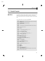
FĂSample operation
Read the PV of unit No.00. (In this example, PV=335.)
RUN
SEND DATA: 000000101C00001000001
RESPONSE: 000000010100000000014F
SEND DATA : [STX] 00 00 0 0101 C0 0001 00 0001 [ETX] [BBC]
Number of elements
Bit position
Read start address
Variable type
MRC/SRC
SID
Sub–address
Node No.
RESPONSE : [STX] 00 00 00 0101 0000 000014F [ETX] [BBC]
Read data
Response code
MRC/SRC
Final code
Sub–address
Node No.
3–10
H8GN
Sample
3.3
Program
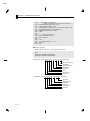
JProtocol macro
F What is a “protocol macro?”
The protocol macro function uses the PMCR command in a ladder proĆ
gram to execute a data send/receive sequence (protocol) with various comĆ
munications devices such as generalĆpurpose components connected to
the RSĆ232C or RSĆ422A/RS Ć485 interface to control the device.
Standard system protocol is preĆinstalled on Serial Communications
Board/Unit for enabling control of OMRON components (e.g. controllers
and temperature control units).
For details on protocol macros, refer to the CS1WĆSCB21/41/ĆSCU21
User's Manual" (Cat. No. W336).
Connection
Use port 2 on the Serial Communications Board (CS1WĆSCB41) for direct
connection to the RSĆ485.
CPU unit
CS1H
Serial Communications Board
CS1W-SCB41
Port 2
RS-485
Set the TERM switch on the Serial Communications Board to ON and the
WIRE switch to “2". Attach a terminator to H8GN.
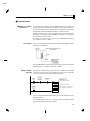
Sample ladder
program
Read the PV of H8GN using sequence No. 600 send/receive with ASCII
conversion (response ON)" of the standard system protocol CompoWay
/F Host" built into the Serial Communications Board.
Input
condition
000000
“Network
communication
command
executable” flag
A20200
“Protocol macro
in progress” flag
191915
Communication port 0
Serial port 2
Destination address E1
(serial communication board)
PMCR
#02E1
#0258
“Network
communication
error” flag
A21900
Sequence No. 0258H (=600)
D01000
First word address for transmission data
D01500
First word address for reception data
FAL(06)
01
The PV is stored to D01502 and D01503 if the read PV command is set to
D01000 onwards.
If a communications error occurs, execute the FAL command (continue
operation and analyze trouble command).
3–11
H8GN
CHAPTER 3 COMMUNICATIONS DATA
FĂData transmission word assignment
STX
Node
No.
Subaddress
SID
MRC
SRC
Variable
type
Address
02H
”01”
”00”
”0”
”01”
”01”
”C0”
”0001”
Bit
position Number of elements EXT BCC
”00”
”0001”
03H
D01000
0007
No. of transmission words (D01000 to D01006)
D01001
0001
Node No. of H8GN: 1
D01002
0101
CompoWay/F command: Variable area read
D01003
000C
No. of bytes transmitted: 12
D01004
C000
D01005
0100
D01006
0001
Variable type, read start address, bit position,
Number of elements
FĂData reception word assignment
STX
Node
No.
Subaddress
02H
”01”
”00”
End
code
MRC
SRC
”01”
”01”
D01500
D01501
Response code
Data
Process value
0004
3–12
03H
Number of reception words (D01500 to D01503)
Response code
D01502
D01503
EXT BCC
Current process value
H8GN
APPENDIX
APPENDIX
ASCII List . . . . . . . . . . . . . . . . . . . . . . . . . . . . . . . . .
AĆ2
A–1
H8GN
APPENDIX
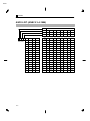
ASCII LIST (ANSI X 3.4-1986)
b8
b7
0
0
0
0
1
1
1
1
b6
0
0
1
1
0
0
1
1
b5
0
1
0
1
0
1
0
1
0
1
2
3
4
5
6
7
0
@
P
1
A
Q
a
q
C
b8 b7 b6 b5
b4
b3
b2
b1
#
Even parity
0
0
0
0
0
NUL
0
0
0
1
1
SOH
DEL SPAC
E
DC1
!
0
0
1
0
2
STX
DC2
”
2
B
R
b
r
0
0
1
1
3
ETX
DC3
#
3
C
S
c
s
0
1
0
0
4
EOT
DC4
$
4
D
T
d
t
0
1
0
1
5
ENQ
NAK
%
5
E
U
e
u
0
1
1
0
6
ACK
SYN
&
6
F
V
f
v
0
1
1
1
7
BEL
ETB
’
7
G
W
g
w
1
0
0
0
8
BS
CAN
(
8
H
X
h
x
1
0
0
1
9
HT
EN
)
9
I
Y
i
y
1
0
1
0
A
LF
SUB
*
:
J
Z
j
z
1
0
1
1
B
VT
ESC
+
;
K
[
k
{
1
1
0
0
C
FF
FS
,
<
L
\
l
|
1
1
0
1
D
CR
GS
-
=
M
]
m
}
A–2
R
p
1
1
1
0
E
SO
RS
.
>
N
^
n
X
1
1
1
1
F
SI
US
/
?
O
_
o
DEL
H8GN
INDEX
Interface . . . . . . . . . . . . . . . . . . . . . . . . . 1Ć2, 1Ć3
A
Addresses . . . . . . . . . . . . . . . . . . . . . . . . . . . . 2Ć5
Area definitions . . . . . . . . . . . . . . . . . . . . . . . 2Ć5
ASCII list . . . . . . . . . . . . . . . . . . . . . . . . . . . AĆ2
B
BCC . . . . . . . . . . . . . . . . . . . . . 1Ć2, 2Ć2, 2Ć3, 2Ć4
L
List of services . . . . . . . . . . . . . . . . . . . . . . . . 2Ć6
N
O
Operation instructions . . . . . . . . . . . 2Ć6, 2Ć14
C
Command frame . . . . . . . . . . . . . . . . . . 1Ć3, 2Ć2
Command text . . . . . . . . . . . . . . . . . . . . 2Ć2, 2Ć5
Communications data . . . . . . . . . . . . . 2Ć4, 3Ć1
Communications data length . . . . . . . 1Ć4, 1Ć5
Communications methods . . . . . . . . . . 1Ć1, 1Ć2
Communications parameters . . . . . . . . . . . 1Ć4
Communications parity . . . . . . . . . . . . 1Ć4, 1Ć5
Communications specifications . . . . . . . . . 1Ć2
Communications stop bit . . . . . . . . . . 1Ć4, 1Ć5
Communications unit No. . . . . . . . . . . 1Ć4, 1Ć5
CompoWay/F . . . . . . . . . . . . . . . . . 1Ć2, 2Ć1, 3Ć1
P
Data format . . . . . . . . . . . . . . . . . . . . . . . . . . 2Ć2
Details of services . . . . . . . . . . . . . . . . . . . . . 2Ć7
E
Echoback test . . . . . . . . . . . . . . . . . . . . 2Ć6, 2Ć12
End code . . . . . . . . . . . . . . . . . . . . . . . . . 2Ć3, 2Ć4
ETX . . . . . . . . . . . . . . . . . . . . . . . . . . . . . 2Ć2, 2Ć3
F
FINS . . . . . . . . . . . . . . . . . . . . . . . . . . . . 1Ć2, 2Ć3
PDU . . . . . . . . . . . . . . . . . . . . . . . . . . . . 2Ć5, 2Ć10
R
Read controller attributes . . . . . . . . . 2Ć6, 2Ć10
Read controller status . . . . . . . . . . . . 2Ć6, 2Ć11
Read from variable area . . . . . . . . . . . 2Ć6, 2Ć7
Response code list . . . . . . . . . . . . . . . . . . . . 2Ć15
Response frame . . . . . . . . . . . . . . . . . . . . . . . 2Ć3
S
Sample program . . . . . . . . . . . . . . . . . . . . . . 3Ć9
SID . . . . . . . . . . . . . . . . . . . . . . . . . . . . . . 2Ć2, 2Ć4
Status . . . . . . . . . . . . . . . . . . . . . . . . . . . . . . . 3Ć6
STX . . . . . . . . . . . . . . . . . . . . . . . . . . . . . . . . . 2Ć2
D
I
Number of elements . . . . . . . . . . . . . . . . . . . 2Ć5
T
Transmission procedure . . . . . . . . . . . . . . . 1Ć3
Type code (variable type) . . . . . . . . . . . . . . 2Ć5
V
Variable area (setup range) list . . . . . . . . . 3Ć2
W
Wiring . . . . . . . . . . . . . . . . . . . . . . . . . . . . . . . 1Ć3
Write to variable area . . . . . . . . . . . . . 2Ć6, 2Ć8
H8GN
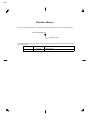
Revision History
A manual revision code appears as a suffix to the catalog number on the front cover of the manual.
Cat. No. M066ĆE1Ć1
Revision code
The following table outlines the change made to the manual during each revision. Page numbers refer
to previous version
Revision code
Data
1
June 2000
Revised content
Original production