1
Preface
OMRON products are manufactured for use according to proper procedures by a qualified operator and
only for the purposes described in this manual.
The ZEN is a compact and highly functional controller that can be used to easily automate small-scale
applications. Its development has drawn on OMRON's advanced control technology and expertise in
manufacturing various types of controllers.
Version 2 of the ZEN includes Economy-type CPU Units and Communications-type CPU Units. Twin timer
operation and operation between days for weekly timers have been added. Pulse output operation and 8digit counters with high-speed counting have also been added, and Expansion I/O Units have been
downsized to half the width.
This manual describes the communications functions of Communications-type CPU Units. When using a
Communications-type CPU Unit, read this manual and be sure to use the communications functions
correctly. Keep the manual close at hand so that you can refer to it whenever necessary.
● Intended Audience
This manual is intended for the following readers.
• Persons in charge of introducing FA devices
• Persons who design FA systems
• Persons who install or connect FA devices
• Persons who manage working FA installations
Persons who use this product must have sufficient knowledge of electrical systems (i.e., an electrical
engineer or the equivalent).
ii
Warranty and Application Considerations
Read and Understand this Manual
Please read and understand this manual before using the product. Please consult your OMRON
representative if you have any questions or comments.
Warranty and Limitations of Liability
Warranty and Limitations of Liability
WARRANTY
OMRON's exclusive warranty is that the products are free from defects in materials and
workmanship for a period of one year (or other period if specified) from date of sale by OMRON.
OMRON MAKES NO WARRANTY OR REPRESENTATION, EXPRESS OR IMPLIED,
REGARDING NON-INFRINGEMENT, MERCHANTABILITY, OR FITNESS FOR PARTICULAR
PURPOSE OF THE PRODUCTS. ANY BUYER OR USER ACKNOWLEDGES THAT THE
BUYER OR USER ALONE HAS DETERMINED THAT THE PRODUCTS WILL SUITABLY MEET
THE REQUIREMENTS OF THEIR INTENDED USE. OMRON DISCLAIMS ALL OTHER
WARRANTIES, EXPRESS OR IMPLIED.
LIMITATIONS OF LIABILITY
OMRON SHALL NOT BE RESPONSIBLE FOR SPECIAL, INDIRECT, OR CONSEQUENTIAL
DAMAGES, LOSS OF PROFITS OR COMMERCIAL LOSS IN ANY WAY CONNECTED WITH
THE PRODUCTS, WHETHER SUCH CLAIM IS BASED ON CONTRACT, WARRANTY,
NEGLIGENCE, OR STRICT LIABILITY.
In no event shall the responsibility of OMRON for any act exceed the individual price of the
product on which liability is asserted.
IN NO EVENT SHALL OMRON BE RESPONSIBLE FOR WARRANTY, REPAIR, OR OTHER
CLAIMS REGARDING THE PRODUCTS UNLESS OMRON'S ANALYSIS CONFIRMS THAT
THE PRODUCTS WERE PROPERLY HANDLED, STORED, INSTALLED, AND MAINTAINED
AND NOT SUBJECT TO CONTAMINATION, ABUSE, MISUSE, OR INAPPROPRIATE
MODIFICATION OR REPAIR.
iii
Application Consideration
SUITABILITY FOR USE
THE PRODUCTS CONTAINED IN THIS DOCUMENT ARE NOT SAFETY RATED. THEY ARE
NOT DESIGNED OR RATED FOR ENSURING SAFETY OF PERSONS, AND SHOULD NOT BE
RELIED UPON AS A SAFETY COMPONENT OR PROTECTIVE DEVICE FOR SUCH
PURPOSES. Please refer to separate catalogs for OMRON's safety rated products.
OMRON shall not be responsible for conformity with any standards, codes, or regulations that
apply to the combination of products in the customer’s application or use of the product.
At the customer’s request, OMRON will provide applicable third party certification documents
identifying ratings and limitations of use that apply to the products. This information by itself is not
sufficient for a complete determination of the suitability of the products in combination with the
end product, machine, system, or other application or use.
The following are some examples of applications for which particular attention must be given.
This is not intended to be an exhaustive list of all possible uses of the products, nor is it intended
to imply that the uses listed may be suitable for the products:
• Outdoor use, uses involving potential chemical contamination or electrical interference, or
conditions or uses not described in this document.
• Nuclear energy control systems, combustion systems, railroad systems, aviation systems,
medical equipment, amusement machines, vehicles, safety equipment, and installations subject
to separate industry or government regulations.
• Systems, machines, and equipment that could present a risk to life or property.
Please know and observe all prohibitions of use applicable to the products.
NEVER USE THE PRODUCTS FOR AN APPLICATION INVOLVING SERIOUS RISK TO LIFE
OR PROPERTY WITHOUT ENSURING THAT THE SYSTEM AS A WHOLE HAS BEEN
DESIGNED TO ADDRESS THE RISKS, AND THAT THE OMRON PRODUCT IS PROPERLY
RATED AND INSTALLED FOR THE INTENDED USE WITHIN THE OVERALL EQUIPMENT OR
SYSTEM.
iv
Disclaimers
Disclaimers
CHANGE IN SPECIFICATIONS
Product specifications and accessories may be changed at any time based on improvements and
other reasons.
It is our practice to change model numbers when published ratings or features are changed, or
when significant construction changes are made. However, some specifications of the products
may be changed without any notice. When in doubt, special model numbers may be assigned to
fix or establish key specifications for your application on your request. Please consult with your
OMRON representative at any time to confirm actual specifications of purchased products.
DIMENSIONS AND WEIGHTS
Dimensions and weights are nominal and are not to be used for manufacturing purposes, even
when tolerances are shown.
PERFORMANCE DATA
Performance data given in this manual is provided as a guide for the user in determining
suitability and does not constitute a warranty. It may represent the result of OMRON's test
conditions, and the users must correlate it to actual application requirements. Actual performance
is subject to the OMRON Warranty and Limitations of Liability.
ERRORS AND OMISSIONS
The information in this document has been carefully checked and is believed to be accurate;
however, no responsibility is assumed for clerical, typographical, or proofreading errors, or
omissions.
Copyright and Copy Permission
Copyright and Copy Permission
COPYRIGHT AND COPY PERMISSION
This document shall not be copied for sales or promotions without permission.
This document is protected by copyright and is intended solely for use in conjunction with the
product. Please notify us before copying or reproducing this document in any manner, for any
other purpose. If copying or transmitting this document to another, please copy or transmit it in its
entirety.
v
Precautions
This section provides precautions for using the ZEN Programmable Relays.
This information contained in this section is important for the safe and reliable application of the ZEN. You must read
this section and understand the information before attempting to set up for a ZEN.
Safety Precautions . . . . . . . . . . . . . . . . . . . . . . . . . . . . . . . . . . . . . . . . . . . . . . viii
Precautions for Safe Use . . . . . . . . . . . . . . . . . . . . . . . . . . . . . . . . . . . . . . . . . x
Precautions for Correct Use . . . . . . . . . . . . . . . . . . . . . . . . . . . . . . . . . . . . . . xii
vii
Precautions
Safety Precautions
Definition of Precautionary Information
The following notation is used in this manual to provide precautions required to ensure safe usage of the product.
The safety precautions that are provided are extremely important to safety. Always read and heed the information
provided in all safety precautions.
The following notation is used.
WARNING
Indicates a potentially hazardous situation which, if not avoided, will result in minor or
moderate injury, or may result in serious injury or death. Additionally, there may be significant
property damage.
CAUTION
Indicates a potentially hazardous situation which, if not avoided, may result in minor or
moderate injury or in property damage.
Symbols
Symbol
Meaning
General Caution
Indicates non-specific general cautions, warnings, and dangers.
Caution
Electrical Shock Caution
Indicates possibility of electric shock under specific conditions.
Explosion Caution
Indicates possibility of explosion under specific conditions.
viii
Prohibition
Disassembly Prohibition
Indicates prohibitions when there is a possibility of injury, such as from electric shock,
as the result of disassembly.
Mandatory
Caution
General Caution
Indicates non-specific general cautions, warnings, and dangers.
Precautions
Precautions
WARNING
Serious human hazard may occasionally occur due to ignition or rupture of the lithium battery used in
the Battery Unit. Do not short the battery terminals or charge, disassemble, deform under pressure,
or incinerate the battery.
Never use any battery that has been dropped on the floor or otherwise
subjected to excessive shock.
CAUTION
Electric shock, fire, or malfunction may occur. Do not disassemble, modify, or repair the ZEN or touch
any of the internal parts.
Electrical shock may occur. Never touch the I/O terminals, computer connector, Expansion Unit
connector, or Battery Unit connector while power is being supplied.
Electrical shock may occur. Do not remove the Expansion Unit connector cover unless an Expansion
I/O Unit will be permanently installed.
Fires may occasionally occur. Tighten the terminal block screws to the specified torque (0.5 to 0.6
N·m) so that they do not become loose.
ix
Precautions
Precautions for Safe Use
Please observe the following precautions for safe use of this products.
Circuit Design
1.
All interface connectors and battery connector are live parts, they may not be directly connected to Softy Extra
Low Voltage (SELV) circuit or to accessible conductive parts.
For the programming units and Personal Computers use only the ZEN-CIF01 Connecting Cable (optional
accessory) manufactured by OMRON.
ZEN-CIF01 provides safe (reinforced) insulation between Personal Computers and ZEN.
2.
Provide emergency stop circuits, external interlock circuits, limit circuits, and other safety circuits in addition to
any provided within the ZEN control circuits to ensure safety of the overall system in the event of ZEN failure or
external factors.
3.
If the ZEN discovers an error during self-diagnosis, operation will be stopped and all outputs will be turned OFF.
As a countermeasure for such problems, external safety measures must be provided to ensure safety in the
overall system.
4.
Outputs from the ZEN may remain ON or OFF due to faults in internal circuits such as output relay fusing or
burning, or output transistor destruction. As a countermeasure for such problems, external safety measures
must be provided to ensure safety in the overall system.
5.
Fail-safe measures must be taken by the user to ensure overall system safety in the event of broken signal lines
or momentary power interruptions.
6.
The durability of the output relays is largely affected by the switching conditions. Confirm the operation of the
system under actual operating conditions and set the switching frequency to ensure that adequate performance
will be provided. Insulation faults and burning in the ZEN may result if relays are used after their performance
has deteriorated.
Connecting Expansion I/O Units
1.
Supply power to both the CPU Unit and Expansion I/O Units from the same power supply and turn them ON
and OFF at the same time.
2.
When connecting Expansion I/O Units with DC inputs to a CPU Unit with an AC power supply, the burst noise
immunity will be 1 kV (IEC 61000-4-4).
3.
Expansion I/O Units with AC inputs (ZEN-8E1AR) cannot be connected to a CPU Unit with a DC power supply.
System Startup and Program Changes
1.
Check the user program for proper execution before actually running it on the Unit.
2.
Disconnect the output lines from the system before testing operation in any system in which incorrect operation
can result in injury or equipment damage.
3.
Confirm safety before attempting any of the following operations.
• Changing the operating mode (RUN/STOP).
• Using the button switches.
• Changing bit status or parameter settings.
4.
Double-check all wiring before turning ON the power supply.
5.
Refer to Cycle Time Calculation Method on page 130 in the ZEN Programmable Relay Operation Manual (Cat.
No. Z211) and confirm that the increase in the cycle time will not affect operation. If the cycle time is too long,
it may become impossible to read input signals accurately. The increase in the cycle time will be particularly
noticeable when set values are written in RUN mode for a CPU Unit with communications (ZEN-10C4@R-@V2).
Installation and Wiring
1.
Do not allow the ZEN to fall during installation.
2.
Be sure that the DIN Track mounting levers, Expansion I/O Units, Memory Cassettes, Battery Units, cable
connectors, and other items with locking devices are properly locked into place. Improper locking may result in
malfunction.
3.
When mounting the ZEN to the surface of the control panel, tighten mounting screws to the following torques.
CPU Units: 1.03 N⋅m max.
Expansion I/O Units: 0.46 N⋅m max.
4.
Use wires with cross-sectional areas of 0.2 to 2.5 mm2 (equivalent to AWG24 to AWG14) for wiring and strip
them for 6.5 mm. If using stranded wires, always connect straight crimp terminals (0.25 to 2.5 mm2).
Handling
1.
x
The environment of use of ZEN is “Pollution degree 2” and “Overvoltage category II” specified in IEC60664-1.
Precautions
2.
Always use the ZEN within the rated ambient operating temperature and humidity. The rated ambient operating
temperature is 0 to 55°C for LCD-type CPU Units and –25 to 55°C for LED-type CPU Units. If the ZEN is used
near sources of heat, such as a power supply, the internal temperature of the ZEN may increase, lowering the
durability of the ZEN.
3.
Discharge static electricity from your body, e.g., by touching a grounded metal plate, before touching any Unit.
4.
The exterior of the Units will be damaged if it comes into contact with organic solvents (e.g., benzene or paint
thinner), strong alkalies, or strong acids. Never allow such substances to come into contact with the Units.
5.
Do not apply voltages exceeding the rated voltages. Internal elements may be destroyed.
6.
Short failures or open failures may result from the destruction of output elements. Do not use loads that exceed
the rated output current.
Maintenance
When replacing a CPU Unit, transfer to the new Unit and confirm all settings for clock data, internal holding bits,
holding timers, and counters before starting operation again.
Transportation and Storage
1.
Use special packaging boxes when transporting the ZEN and do not subject it to excessive shock or vibration
or drop it during shipment.
2.
Store the ZEN at an ambient temperature of −40 to 75°C for LED-type CPU Units and −20 to 75°C for all other
types of CPU Units. If the ZEN has been stored at −10°C or lower, allow it to stand at room temperature for 3
hours or longer before turning ON the power supply.
xi
Precautions
Precautions for Correct Use
Installation Environment
1.
Do not install the ZEN in the following locations.
• Locations subject to radical changes in temperature
• Location with high humidity subject to condensation
• Locations subject to excessive dust or dirt
• Locations subject to corrosive gas
• Locations subject to direct sunlight
2.
Do not install the ZEN in locations subject to shock or vibration. Extended use in such location may cause
damage from stress.
3.
In environments subject to static electricity (e.g., close to pipes conveying forming materials, powders, or fluid
materials), separate the ZEN as far as possible from the source of static electricity.
4.
The ZEN is neither waterproof nor oil-proof. Do not use it in locations subject to water or oil.
5.
Use the ZEN within the allowable power supply voltage range. Be particularly careful in locations with bad power
supply conditions, e.g., large fluctuations in the power supply voltage.
6.
Do not install the ZEN in locations subject to excessive noise, which may cause the ZEN to fail.
7.
Take appropriate and sufficient countermeasures when installing systems in the following locations:
• Locations subject to strong electromagnetic fields
• Locations subject to possible exposure to radioactivity
Power Supply
1.
Always turn OFF the power supply to the ZEN (CPU Unit and Expansion I/O Units) before attempting any of the
following.
• Assembling the ZEN
• Attaching or removing Expansion I/O Units
• Connecting or disconnecting any cables or wiring
• Attaching or removing the Memory Cassette
• Attaching or removing the Battery Unit
2.
If the power supply is interrupted for 2 days or more (at 25°C), the internal capacitor will discharge and internal
bit status and the contents of PV areas will be lost or corrupted and dates and times will be reset. When
restarting operation after the power supply has been interrupted for an extended period of time, check the
system in advance to confirm that no errors will occur.
Handling
1.
Connect connectors only after confirming that the direction or polarity is correct.
2.
Failures could result if dust or dirt enters the ZEN. Always connect the connector cover to the computer
connector whenever it is not being used.
3.
Do not remove the label from the left side of the CPU Unit if a Battery Unit is not mounted.
EEPROM Write Life
The EEPROM has a limited write life. The write life may be exceeded if communications are used frequently to
write settings. Consider this in the system design.
Other
xii
1.
The execution of the ladder program in the ZEN is different from that for other PLCs. Refer to Appendix B Ladder
Program Execution in the ZEN Programmable Relay Operation Manual (Cat. No. Z211) when writing the ladder
program.
2.
Abide by all local ordinances and regulations when disposing of the ZEN.
3.
The Battery Unit (ZEN-BAT01, sold separately) contains a lithium battery. Observe all applicable legal
requirements for your area when disposing of the lithium battery.
Conventions Used in This Manual
This user's manual describes the communications functions of CPU Units with communications. For information on using other functions, refer to the ZEN Programmable Relay Operation Manual.
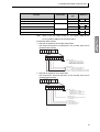
■ Manual Contents
Item
Description
SECTION 1
Communications Methods
This section briefly describes the supported
communications methods and how to wire
equipment. Refer to this section before setting up equipment.
SECTION 2
CompoWay/F
Communications Protocol
This section describes the protocol for
communications using the CompoWay/F
format.
SECTION 3
Communications Data
This section lists the details of the
communications data in the CompoWay/F
communications protocol.
Appendix
ASCII list
■ Related Manuals
ZEN Programmable Relay Operation Manual (Z211)
ZEN Support Software Operation Manual (Z184)
xiii
Revision History
■ Manual Revision Code
A manual revision code appears as a suffix to the catalog number on the front and
back cover of the manual.
Man. No.
Z212-E1-01
■ Revision History
The following table outlines the changes made to the manual during each revision.
Page numbers refer to the previous version.
Revision code
01
xiv
Date
April 2006
Revised content
Original production
Table of Contents
SECTION 1
Communications Methods
1.1
Preface - - - - - - - - - - - - - - - - - - - - - - - - - - - - - ii
Warranty and Application Considerations - - - - - iii
Precautions - - - - - - - - - - - - - - - - - - - - - - - - - -vii
Conventions Used in This Manual - - - - - - - - - - xiii
Revision History - - - - - - - - - - - - - - - - - - - - - - xiv
Overview of Communications Methods ......................................................... 2
Introduction ............................................................................................ 2
Communications Specifications ............................................................. 2
Transmission Procedure ........................................................................ 3
Interface ................................................................................................. 3
Wiring ..................................................................................................... 3
Communications Parameters ................................................................. 4
Setting Communications Parameters .................................................... 5
SECTION 2
CompoWay/F Communications Protocol
2.1
Data Format ................................................................................................ 10
2.2
Command Frame ................................................................................. 10
Response Frame ................................................................................. 11
Communications Data .......................................................................... 12
Structure of Command Text ........................................................................ 14
2.3
PDU Structure ...................................................................................... 14
Addresses ............................................................................................ 14
Number of Elements ............................................................................ 14
List of Services ..................................................................................... 15
Detailed Description of the Services ........................................................... 16
2.4
Read Variable Area .............................................................................. 16
Variable Type and Read Start Address ............................................... 16
Bit Position ........................................................................................... 16
Number of Elements ............................................................................ 16
Response Code ................................................................................... 16
Reading Timers, Counters, and Comparators ..................................... 17
Reading Work Bits and HR Bits ........................................................... 20
Write Variable Area .............................................................................. 21
Writing Timer and Counter Set Values ................................................ 22
Writing Work Bits and HR Bits ............................................................. 26
Read Controller Attributes .................................................................... 26
Read Controller Status ......................................................................... 27
Read Time Data ................................................................................... 28
Write Time Data ................................................................................... 29
Echoback Test ..................................................................................... 31
Operation Command ............................................................................ 32
Response Code List .................................................................................... 34
SECTION 3
Communications Data
3.1
Variable Area (Data Range) List ................................................................. 36
Appendix
ASCII List .............................................................................................................. 42
INDEX ................................................................................................................... 43
xv
xvi
SECTION 1
Communications Methods
This section briefly describes the supported communications methods and
how to wire equipment. Refer to this section when setting up equipment.
1.1
Overview of Communications Methods ........................... 2
Introduction................................................................. 2
Communications Specifications.................................. 2
Transmission Procedure............................................. 3
Interface...................................................................... 3
Wiring ......................................................................... 3
Communications Parameters ..................................... 4
Setting Communications Parameters ......................... 5
1
SECTION 1 Communications Methods
Overview
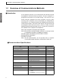
1.1 Overview of Communications Methods
■ Introduction
A host computer (see note 1) can communicate with the ZEN using the
CompoWay/F communications protocol. The host computer is
programmed to monitor and set ZEN settings. This manual is thus
written from the viewpoint of the host computer. Up to 32 nodes
including host computers can be connected via CompoWay/F.
CompoWay/F is an integrated protocol for OMRON general-purpose
serial communications. Consistent frame formats and commands that
are compliant with FINS (see note 2), which is widely used with
OMRON Programmable Controllers (PLCs), enable easy communications between a host computer and components.
Note 1:Host computers include personal computers.
Note 2:FINS (Factory Interface Network Service) is a message service
used between controllers on OMRON FA networks.
The ZEN supports the following communications functions.
• Reading/writing of parameters
• Operation instructions
Note: RS-485 communications are not possible when a computer
running ZEN Support Software is online with the CPU Unit.
■Communications Specifications
Item
2
Details
Default settings
Transmission line connection
Multi-drop
None
Communications method
RS-485 (2-wire, half-duplex)
None
Synchronization method
Start-stop synchronization
None
Communications baud rate
4800, 9600, or 19200 bps
9600 bps
Communications code
ASCII
None
Communications data bits
7 or 8 bits
7 bits
Communications stop bits
1 or 2 bits
2 bits
Error detection
Vertical parity (none, even, or odd)
Even
BCC (Block Check Character)
None
Flow control
None
---
Interface
RS-485
---
Retry function
None
---
Communications buffer
36 bytes
---
Communications protocol
CompoWay/F
None
Number of nodes
1:1 connection:
1 node
1:N connections:
32 nodes max. including host computer
None
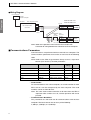
1.1 Overview of Communications Methods
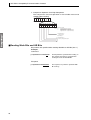
■ Transmission Procedure
When the host computer transmits a command frame, the ZEN
transmits a response frame that corresponds to the command frame. A
single response frame is returned for each command frame. The
frames.
Command frame
Command frame
Host computer
ZEN
Response frame
Note: Allow a wait time of at least 2 ms before the next command is
sent after the host computer receives a response from the ZEN.
■ Interface
Use of the following Converter for RS-232C and RS-485 interface
conversion is recommended.
Name
Interface Converter (OMRON)
Model
K3SC
Details
Communications between the host computer
and the ZEN conform to the RS-485 interface.
■ Wiring
This section explains how to perform the ZEN’s communications wiring.
For details on the host computer, refer to the user documentation
provided with the host computer.
• Match the communications specifications of the ZEN and the host
computer.
• The connection format can be either one-to-one or one-to-N.
• Up to 32 units including the host computer can be connected in a oneto-N system.
• The total cable length is 500 m max.
• Use a shielded twisted-pair cable with wires of a thickness of AWG28 to
AWG14 for communications signal wiring.
Note: When using a 1:N connection, set the same communications
specifications in all of the Units, and set a unique node number
for each Unit.
3
Overview
following diagram shows the operation of the command and response
SECTION 1 Communications Methods
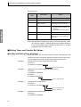
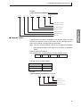
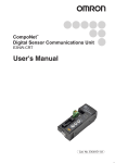
● Wiring Diagram
Host computer
Overview
Example:
Personal computer
RS-232C
ZEN-10C4AR-A-V2
Host computer: RS-485
RS-485
Signal
RS-232C/RS-485
Converter
ZEN-10C4DR-D-V2
Signal
Terminal
FG
+
−
SG
B (+)
A (−)
Shield
Comm.
RS-485 (+)
terminals
RS-485 (−)
Terminator:
ZEN
120 Ω
(1/2 W) End node
RS-485
Signal
Terminal
B (+)
A (−)
End node
RS-485 (+) comm.
RS-485 (−) terminals
Use a terminator of 120 Ω (1/2 W).
Shield
Note: Refer to the operation manual for the RS-232C/RS-485
Converter for wiring between the Converter and host computer.
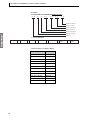
■ Communications Parameters
Communications are performed with an external host computer. The
communications parameters that can be set are listed in the following
table.
Note: Refer to the ZEN Programmable Relay Version 2 Operation
Manual (Cat. No. Z211) for other parameters.
Item
Display
Set values
Default
settings
Unit
Node number
NODE NO
00 or 01 to 99
1
---
Communications baud rate
COM SPEED
4800, 9600, or 19200
9600
bps
Communications data length
DATA BIT
7 or 8
7
bit
Stop bits
STOP BIT
1 or 2
2
bit
Parity
PARITY
None, even, or odd
Even
---
• Node Number
For communications with a host computer, set a node number for each
ZEN so that it can be recognized by the host computer. The node
numbers can be set from 00 to 99.
Note: The same node number cannot be set for more than one ZEN. If
duplicate node numbers are set, correct operation will not be
possible.
• Communications Baud Rate
This parameter sets the baud rate for communications with the host
computer. The baud rate can be set to any of the following:
4,800 bps, 9,600 bps, or 19,200 bps.
4
1.1 Overview of Communications Methods
• Communications Data Length
This parameter sets the number of communications data bits. Set either
7 bits or 8 bits.
• Stop Bits
1 or 2.
• Parity
This parameter sets the communications parity. Set the parity to none,
even, or odd.
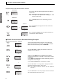
■ Setting Communications Parameters
Set the communications parameters for the ZEN from the ZEN Support
Software or from the RS-485 communications submenu of the CPU
Unit.
• Settings cannot be changed in RUN mode. Switch to STOP mode first
using the following procedure and then set the communications
parameters.
• Any communications parameters that are set are valid from the next
time a communication is received.
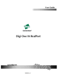
● Changing from RUN Mode to STOP Mode
RUN Mode
Power
ON
The screen to the left is displayed when the power is turned
ON.
MO11:17 RUN
I:oooooo
Q:[[[[
RUN
↓
Main Menu
2
MONITOR
STOP
PARAMETER
SET CLOCK
RUN
→
MONITOR
STOP
PARAMETER
SET CLOCK
Press the OK Button to display the Menu Screen.
Press the Down Button to move the flashing cursor to
STOP.
RUN
↓
PROGRAM
RUN
PARAMETER
SET CLOCK
Press the OK Button to switch the display to RUN.
Refer to Displaying the RS-485 Communications Submenu
on page 6 to display the RS-485 Communications Submenu.
5
Overview
This parameter sets the number of communications stop bits. Set either
SECTION 1 Communications Methods
Displaying the RS-485 Communications Submenu
Overview
STOP Mode
The screen at the left will be displayed when the ZEN is in
STOP mode.
Press the OK Button to display the Menu Screen.
Note: This step is not required after switching from RUN
Mode to STOP mode.
MO13:15 STOP
I:oooooo
(See
note.)
Q:[[[[
Main Menu
2
Press the Down Button to move the flashing cursor to
RS485.
PROGRAM
RUN
PARAMETER
SET CLOCK
Submenu
SET CLOCK
LANGUAGE
RS485
OTHER
NODE NO
COM SPEED
DATA BIT
STOP BIT
→
Press the OK Button to display the RS-485 Communications Submenu.
↓
Power
ON
COM SPEED
DATA BIT
STOP BIT
PARITY
2
5
Press the Up and Down Buttons to move the flashing cursor to the items on the submenu.
● RS-485 Communications Submenu Setting Examples
RS-485 Communications Submenu
Power
ON
2
5
The RS-485 Communications Submenu Screen will be displayed when the power is turned ON. Use the Up and Down
Buttons to move the flashing cursor to NODE NO.
NODE NO
COM SPEED
DATA BIT
STOP BIT
↓
Press the OK Button to display the currently set value. The
highlighted cursor will flash.
RS485
NODE NO
01
RUN
↓
RS485
NODE NO
3 4
5
09
RUN
2
Again press the OK Button. The highlighted cursor will be
changed to a flashing cursor, and the set value will be ready to
be changed.
Use the Right and Left Buttons to move the flashing cursor to
the digit that is to be changed.
Use the Up and Down Buttons to change the number.
↓
(See
note.)
RS485
SET?
OK/ESC
RUN
09
Press the OK Button. A message will be displayed to confirm
whether the changed setting is to be saved.
Note: The setting will not be saved if the ESC Button is
pressed.
↓
NODE NO
COM SPEED
DATA BIT
STOP BIT
6
Press the OK Button to save any changes and return to the RS485 Communications Submenu Screen.
1.1 Overview of Communications Methods
↓
Main Menu
Press the ESC Button to return to the Menu Screen.
Overview
SET CLOCK
LANGUAGE
RS485
OTHER
7
Overview
SECTION 1 Communications Methods
8
SECTION 2
CompoWay/F Communications Protocol
This section describes the protocol for communications using the
CompoWay/F format.
2.1
2.2
2.3
2.4
Data Format................................................................... 10
Command Frame.................................................... 10
Response Frame .................................................... 11
Communications Data ............................................ 12
Structure of Command Text ........................................... 14
PDU Structure ........................................................ 14
Addresses............................................................... 14
Number of Elements............................................... 14
List of Services ....................................................... 15
Detailed Description of the Services.............................. 16
Read Variable Area ................................................ 16
Variable Type and Read Start Address .................. 16
Bit Position.............................................................. 16
Number of Elements............................................... 16
Response Code...................................................... 16
Reading Timers, Counters, and Comparators........ 17
Reading Work Bits and HR Bits.............................. 20
Write Variable Area ................................................ 21
Writing Timer and Counter Set Values ................... 22
Writing Work Bits and HR Bits................................ 26
Read Controller Attributes ...................................... 26
Read Controller Status ........................................... 27
Read Time Data ..................................................... 28
Write Time Data...................................................... 29
Echoback Test........................................................ 31
Operation Command .............................................. 32
Response Code List ...................................................... 34
9
SECTION 2 CompoWay/F Communications Protocol
2.1 Data Format
For CompoWay/F, numeric values for commands are converted to ASCII and expressed as hexadecimal
values.
• Numbers prefixed with H’ are hexadecimal, e.g., H’02 is 02 hexadecimal.
• The numbers below the various parts of a frame specify the number of bytes.
• Unless specified, all other numbers are ASCII characters. (Refer to the Appendix for a table of ASCII
characters.)
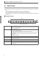
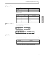
■ Command Frame
Text
Node number Sub-address SID
STX
0
1
2
0
2
BCC
FINS-mini command text
0
1
BCC calculation range
ETX
1
1
STX
This code (H’02) indicates the beginning of the communications frame (text).
Always set STX in the first byte.
When STX is received again during reception, reception is carried out again from the point
where STX was received.
Node number
•
•
•
•
Sub-address
The sub-address is not used in the ZEN. It must be fixed at “00.”
SID
• Service ID. The service ID is not used in the ZEN.
• Be sure to set it to “00.”
Command text
This is the command text area. For details, see 2.2 Structure of Command Text.
ETX
This code (H’03) indicates the end of the text.
BCC
• This is the Block Check Character.
• The BCC result is found by calculating the exclusive OR of the bytes from the node number up to ETX.
10
This number specifies the transmission destination.
Specify the ZEN’s node number.
A BCD value between 00 and 99 or an ASCII value of XX can be set.
Specify “XX” for a broadcast transmission. No responses will be returned for broadcast
transmissions.
• No responses will be returned from node numbers other than the ones in the above
range.
• The default setting is 01.
2.1 Data Format
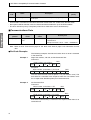
● BCC Calculation Example
The BCC (Block Check Character) is determined by calculating the
exclusive OR of the bytes from the node number up to ETX. The 8-bit
result is written to the BCC byte at the end of the frame.
STX
SID
Node number Sub-address
Command text
H'02 0 (H'30) 0 (H'30) 0 (H'30) 0 (H'30) 0 (H'30) 0 (H'30) 5 (H'35) 0 (H'30) 3 (H'33)
ETX
BCC
H'03
H'35
BCC = H'30+H'30+H'30+H'30+H'30+H'30+H'35+H'30+H'33+H'03 = H'35
The result of the calculation (35 hex) is written to the BCC byte.
The + symbols indicate XOR (exclusive OR) operations.
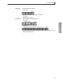
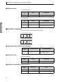
■ Response Frame
Node number
Sub-address
End code
BCC
Command text
STX
ETX
1
2
2
2
1
1
● End Codes
Normal Completion
End
code
00
Name
Normal completion
Description
The command ended normally without error.
Error detection
priority
None
Error Occurred
End
code
Name
Description
Error detection
priority
0F
FINS command error
The specified FINS command could not be executed.
The FINS response code should indicate why the command
could not be executed.
8
10
Parity error
The sum total of bits whose received data is 1 does not
match the set value of the “communications parity” bit.
2
11
Framing error
Stop bit is 0.
1
12
Overrun error
New data was transferred when the reception data buffer
was already full.
3
13
BCC error
The calculated BCC value is different from the received
BCC value.
5
14
Format error
• The command text contains characters other than 0 to 9,
and A to F.
Note: This error does not apply to Echoback Tests. Refer
to Echoback Test on page 31 for details.
• There was no SID and command text. There was no command text.
• “MRC/SRC” not included in command text.
7
16
Sub-address error
• Illegal (unsupported) sub-address
• There was no sub-address, SID, and command text.
• Sub-address was less than two characters, and there was
no SID and command text.
6
11
SECTION 2 CompoWay/F Communications Protocol
End
code
18
Name
Frame length error
Error detection
priority
Description
The received frame exceeds the specified (supported) number of bytes.
4
• An end code is returned for each command frame received that was addressed to the local node.
• No response will be returned unless the frame contained all elements up to the ETX and BCC.
• The Error detection priority is the priority when two or more errors occur simultaneously.
■ Communications Data
Communications
protocol
CompoWay/F
Set (monitor)
values
8-digit hexadecimal
Negative
values
Decimal point
2’s complement
Decimal point is removed and the result is converted
to hexadecimal.
Example conversion: 105.0 → 1050 → H’0000041A
Note: Refer to Read Time Data on page 28 and Write Time Data on page 29 for information on time
data.
● End Code Examples
The following examples describe end codes when an error is detected
in the command.
Example 1
Illegal Sub-address, No SID, and No Command Text
Command
Node number Sub-address
STX
0
A
BCC
ETX
Response
Node number Sub-address End code
STX
0
A
1
6
BCC
ETX
The end code returned in the response is 16 (sub-address error). The
end code 16 is returned in the response when the sub-address error
has a higher error detection priority than the format error.
Example 2
No Command Text
Command
Node number Sub-address SID
STX
0
0
0
BCC
ETX
Response
Node number Sub-address End code
STX
0
0
1
4
BCC
ETX
End code 14 (format error) is returned in the response when there is no
command text.
12
2.1 Data Format
Example 3
No Node Number Provided
Command
BCC
STX
ETX
The node number is missing one character.
Response
No response is made.
Example 4
No Sub-address and Illegal BCC
Command
Node number
STX
BCC
ETX
Err
Response
Node number Sub-address
STX
0
0
BCC
End code
1
3
ETX
The sub-address is taken as 00 and end code 13 (BCC error) is
returned in the response.
13
SECTION 2 CompoWay/F Communications Protocol
2.2 Structure of Command Text
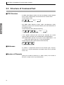
■ PDU Structure
• An MRC (Main Request Code) and SRC (Sub-Request Code) followed
by the various required data are transferred in the command text.
Service Request PDU
MRC SRC
Data
• The MRES (Main Response Code), SRES (Sub-Response Code),
followed by the data are transferred following the above MRC/SRC in
the response frame.
Service Response PDU (Normal Response)
MRC SRC MRES SRES
Data
• If the specified command text could not be executed, the service
response PDU will contain only the MRC/SRC and MRES/SRES.
Note: MRES/SRES provides the response code. MRES/SRES is not
output when processing ends in a normal completion.
Service Response PDU (Command Text Not Executed)
MRC SRC MRES SRES
■ Addresses
An address is appended to each of the variable types. Express
addresses in 2-byte hexadecimal and append them for the specified
access size.
■ Number of Elements
Specify the number of elements as “0001” (fixed). The number of
elements is expressed in 2-byte hexadecimal.
14
2.2 Structure of Command Text
■ List of Services
MRC
SRC
Name of service
Processing
01
01
Read Variable Area
This service reads from variable areas.
01
02
Write Variable Area
This service writes to variable areas.
05
03
Read Controller Attributes
This service reads the model number and communications buffer size.
06
01
Read Controller Status
This service reads the operating status.
07
01
Read Time Data
This service reads ZEN time data.
07
02
Write Time Data
This service sets ZEN time data.
08
01
Echoback Test
This service performs an echoback test.
30
05
Operation Command
This service switches between RUN and STOP.
Note: No commands will be accepted and no responses will be
returned when a memory error has occurred or the Controller is
initializing (until normal operation begins after the power is
turned ON).
15
SECTION 2 CompoWay/F Communications Protocol
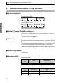
2.3 Detailed Description of the Services
■ Read Variable Area
This service reads data from a variable area.
Service Request PDU
MRC SRC
Variable
type
Read
start address
Bit
position
Number of
elements
2
4
0 1 0 1
2
2
2
4
Service Request PDU
MRC SRC
Response
code
Read data (for number
of elements)
0 1 0 1
8 or 12 (See note.)
2
2
4
Note: The read data 12 indicates the weekly timer.
■ Variable Type and Read Start Address
For details on variable types and read start addresses, refer to 3.1
Variable Area (Data Range) List.
Variables of type C0 are read-only.
■ Bit Position
Bits positions are always 00 except for work bits and HR bits. With the
ZEN, bit access supported only for work bits and HR bits.
For details on bits and applications methods, refer to 1-4 Memory Areas
in the ZEN Programmable Relay Operation Manual (Cat. No. Z211).
Note: Refer to Reading Work Bits and HR Bits on page 20 for details on
reading work bits and HR bits.
■ Number of Elements
Always 0001.
■ Response Code
Normal Completion
Response
code
0000
Name
Normal completion
Description
No errors were found.
Error Occurred
Response
code
16
Error name
Cause
1001
Command too long
The command is too long.
1002
Command too short
The command is too short.
2.3 Detailed Description of the Services
Response
code
Error name
Cause
1101
Area type error
The variable type is wrong.
110B
Response too long
The number of elements is greater
than 0001.
1100
Parameter error
• Bit position is not 00.
• The bit address is out of range.
2203
Operation error
Unit error (memory error occurred,
or unused command was sent.)
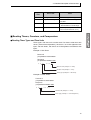
■ Reading Timers, Counters, and Comparators
● Reading Timer Types and Time Units
Timer types and time units can be read. For timers other than twin
timers (normal timer operation), the data is set in the rightmost four
bytes. For twin timers, the data is set in the rightmost and leftmost two
bytes.
Example 1: Twin Timer
Command
[STX]000000101C00001000001
Response
[STX]000000101000000410002
0
0 4
1
0 0
0
2
OFF time unit (example: 2 = H:M)
ON time unit (example: 1 = M:S)
Timer type (example: 4 = twin timer)
Example 2: Other Timers
Command
[STX]000000101C00001000001
Response
[STX]000000101000000110000
0
0 1 1
0 0 0 0
ON time unit (example: 1 = H:M)
Timer type (example: 1 = OFF delay timer)
17
SECTION 2 CompoWay/F Communications Protocol
• Timer and Counter Number Specifications
There is more than one timer and more than one counter, and so the
leftmost two digits of the address are used to specify the applicable
timer or counter. The timer and counter numbers and corresponding
addresses are given in the following table.
Contents
Timer PV
Variable
type
Type/number
T0 to Tf (16 timers)
Addresses
C0
0000 to 0F00
Timer type and time unit
C0
0001 to 0F01
Timer SV
C1
0000 to 0F00
C0
0003 to 0703
Holding timer type and time unit
C0
0004 to 0704
Holding timer SV
C2
0000 to 0700
C0
000B to 0F0B
C5
0000 to 0F00
Holding timer PV
#0 to #7 (8 timers)
Weekly timer operation mode
@0 to @f (16 timers)
Weekly timer SV
Calendar timer SV
*0 to *f (16 timers)
C6
0000 to 0F00
Counter PV
C0 to Cf (16 counters)
C0
0006 to 0F06
C3
0000 to 0F00
Counter SV
● Reading Comparators
RS-485 communications can be used to read the variable area and
perform comparisons with the following three types of comparators.
1. Analog Comparators: Compare an analog input with a constant or
two analog inputs.
2. Comparators: Compare the present value of a timer, holding timer,
or counter with a constant or the present values of timers, holding
timers, or counters.
3. Eight-digit comparators: Compare the present value of an 8-digit
comparator with a constant.
Note: Refer to 3-10 Analog Inputs (Analog Comparators (A)), 3-11
Comparing Timer/Counter Present Values Using Comparators
(P), and 3-12 Comparing the 8-Digit Counter (F) Present Value
Using 8-Digit Comparators (G) in the ZEN Programmable Relay
Operation Manual (Cat. No. Z211) for details on comparators.
• Comparator Number Specifications
There is more one of some types of comparators and more than one
analog input, and so the leftmost two digits of the address are used to
specify the applicable timer or counter. The comparator and analog
input numbers and corresponding addresses are given in the following
table.
Contents
Analog input PV
18
Type/number
I4 and I5
Variable
type
C0
Addresses
I4: 000D
I5: 010D
2.3 Detailed Description of the Services
Contents
Variable
type
Type/number
Analog comparator constant
A0 to A3
Analog comparator operator
Comparator operator
P0 to Pf
Comparator PV
8-digit comparator operator
G0 to G3
8-digit comparator constant
Addresses
C7
0000 to 0300
C0
000E to 030E
C0
000E to 0F0E
C8
0000 to 0F00
C0
0012 to 0312
C9
0000 to 0300
Note: There is only one 8-digit counter (F). Use address 0008 for the
PV and address 0009 for the counting speed.
• Comparator Data Formats
1. Comparison Operators for Analog Comparators
The comparison pattern and operator in the variable area can be
specified when reading.
0
0
Read data
0
0
0
0
8
7
6
5
4
0
3
2
1
0
0
0
0
Comparison Operator
0: ≤
(Analog comparator bit turns ON when
Comparison data 1 ≤ Comparison data 2.)
1: ≥
(Analog comparator bit turns ON when
Comparison data 1 ≥ Comparison data 2.)
Comparison Pattern
0000 (H'0): Compare PV of I4 (Ia: analog input 1)
with PV of I5 (Ib: analog input 2)
0001 (H'1): Compare I4 (Ia: analog input 1) with SV (constant)
0001 (H'1): Compare I5 (Ib: analog input 2) with SV (constant)
2. Comparison Operators for Comparators
The comparison data and operation in the variable area can be
specified when reading.
Read data
0
0
0
0
0
0
8
7
0
6
5
4
3
2
1
0
0
0
Comparison Operator
0: ≤
(Comparator bit turns ON when
Comparison data 1 ≤ Comparison data 2.)
1: ≥
(Comparator bit turns ON when
Comparison data 1 ≥ Comparison data 2.)
Comparison Data 2
0: Timer (T), holding timer (#), or counter (C) PV
1: SV (constant)
Comparison Data 1
000 (H'0): Timer (T) PV
001 (H'0): Holding timer (#) PV
010 (H'0): Counter (C) PV
19
SECTION 2 CompoWay/F Communications Protocol
3. Comparison Operators for 8-Digit Comparator
The comparison data and operation in the variable area can be
specified when reading.
Read data
0
0
0
0
0
0
8
7
6
5
4
3
0
2
0
1
0
0
Comparison Operator
0: ≤
(Comparator bit turns ON when
8-digit counter PV ≤ Comparison data 2.)
1: ≥
(Comparator bit turns ON when
8-digit counter PV ≥ Comparison data 2.)
Comparison Data 2
1: SV (constant)
Note: Always 1.
Comparison Data 1
000 (H'0): 8-digit counter (F) PV
■ Reading Work Bits and HR Bits
Bit positions are specified when reading Work Bits or HR Bits (0 or 1).
Example
Command
[STX]000000101CA000002001
The bit position is specified when reading. In
this example, the bit 02 is specified when
reading the status of Work Bit M2.
Response
[STX]00000010100000000001
20
The response says that the specified Work
Bit is ON (1).
2.3 Detailed Description of the Services
■ Write Variable Area
This service writes data to a variable area.
Service Request PDU
Write Data
Number of
elements (for number of elements)
0 1 0 2
0 0 0 1
2
2
2
4
2
4
8 or 12 (See note.)
Note: The write data 12 indicates the weekly timer.
MRC SRC
Variable
type
Bit
position
Start
write address
Service Response PDU
MRC SRC Response
code
0 1 0 2
2
2
4
● Variable Type and Write Start Address
For details on variable types and write start addresses, see 3.1 Variable
Area (Data Range) List.
Variable type C0 is read-only.
● Bit Position
Bits positions are always 00 except for work bits and HR bits. With the
ZEN, bit access supported only for work bits and HR bits.
For details on bits and applications methods, refer to 1-4 Memory Areas
in the ZEN Programmable Relay Operation Manual.
Note: Refer to Reading Work Bits and HR Bits on page 20 for details
on reading work bits and HR bits.
● Number of Elements
Always to 0001.
● Response Code
Normal Completion
Response
code
0000
Name
Normal completion
Description
No errors were found.
21
SECTION 2 CompoWay/F Communications Protocol
Error Occurred
Response
code
Error name
Cause
1002
Command too short
The command is too short.
1101
Area type error
The variable type is wrong.
1003
Number of elements/
data mismatch
The number of data does not
match the number of elements.
1100
Parameter error
• Bit position is not 00.
• The write data is out of the setting range.
• The bit number is out of range.
3003
Read-only error
Variable type “C0” was written to.
2203
Operation error
Unit error (Memory error
occurred, or unused command
was sent.)
Note: With the Write Variable Area service, “command too long” errors
do not occur. If there is sufficient data for the number of elements
in the service request PDU, the error is processed as a “number
of elements/data mismatch” error.
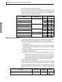
■ Writing Timer and Counter Set Values
● Reading and Writing Timer Set Values
Timer set values (SVs) can be read and written. The rightmost and
leftmost four bytes contain the ON time and OFF time for twin timers
and the rightmost four bytes contain the ON time for other timers.
Example 1:
Writing the SV of Timers Other Than Twin Timers
Command
[STX]000000102C100000000010000270F
ON time: 9999 (H'270F)
Example 2:
Reading the SV of Timers Other Than Twin Timers
Command
[STX]000000101C10000000001
Response
[STX]00000010100000000270F
ON time: 9999 (H'270F)
Example 3:
Writing the SV of Twin Timers
Command
[STX]000000102C100000000010064 270F
OFF time: 9999 (H'270F)
ON time: 100 (H'64)
Example 4:
Writing the SV of Twin Timers
Command
[STX]000000101C10000000001
22
2.3 Detailed Description of the Services
Response
[STX]00000010100000064 270F
OFF time: 9999 (H'270F)
ON time: 100 (H'64)
● Timer, Counter, and Comparator Number Specifications
There is more than one timer and more than one counter, and so the
leftmost two digits of the address are used to specify the applicable
timer or counter. Refer to tables in Timer and Counter Number Specifications on page 18 and Comparator Number Specifications on page 18
for the timer, counter, and comparator numbers and corresponding
addresses.
● Weekly Timers
Weekly timers are built into the ZEN. The following three operations are
possible for weekly timers by combining the day of the week, time, and
output time. These can be written using RS-485 communications.
1. Normal Operation: The bit is turned ON and OFF at the set day and
times.
2. Multiple-day Operation: The bit is turned ON and OFF at the set
days and times (operation across multiple days).
3. Pulse Operation: The bit is turn ON for the set output time at the set
start time and day.
Note: refer to 3-8 Using Weekly Timers (@) in the ZEN Programmable
Relay Operation Manual (Cat. No. Z211) for details on Weekly
Timers.
• Weekly Timer Data Format
The weekly timer data format consists of the following 12 bytes.
1. Normal Operation
2. Multiple-day Operation
Always 00.
2
+
Start day
1
+
End day
+
Start time, hour +
1
Start time, minutes +
2
2
End time, hour
2
+
End time, minutes
2
The time data is as follows (BCD):
Time data
BCD
Sunday
0
Monday
1
Tuesday
2
Wednesday
3
Thursday
4
Friday
5
Saturday
6
No day designated
7
Hour
00 to 23
Minutes
00 to 59
23
SECTION 2 CompoWay/F Communications Protocol
Example
[STX]010000102C5000000001005623592359
0 0
5
6
2
3
5 9
2 3
5
9
End time: 59 minutes
End time: 23 hours
Start time: 59 minutes
Start time: 23 hours
End day: Saturday (6)
Start day: Friday (5)
Always 00.
3. Pulse Operation
Always 00.
2
+
Start day
1
+
End day
+
Start time, hour +
1
Start time, minutes +
2
2
The time data is as follows (BCD):
Time data
24
BCD
Sunday
0
Monday
1
Tuesday
2
Wednesday
3
Thursday
4
Friday
5
Saturday
6
No day designated
7
Start time, hour
00 to 23
Start time, minutes
00 to 59
Output time, minutes
00 to 99
Output time, seconds
00 to 59
Output time,
minutes
2
+
Output time,
seconds
2
2.3 Detailed Description of the Services
Example
[STX]010000102C5000000001005623591520
0
0
5
6
2
3
5
9
1
5
2
0
Output time: 20 seconds
Output time: 15 minutes
Start time: 59 minutes
Start time: 23 hours
End day: Saturday (6)
Start day: Friday (5)
Always 00.
● Calendar Timers
Calendar timers are built into the ZEN. The calendar timers turn ON
between the specified start and end days of the specified months.
These can be written using RS-485 communications.
Note: refer to 3-9 Using Calendar Timers (*) in the ZEN Programmable
Relay Operation Manual (Cat. No. Z211) for details on Calendar
Timers.
• Calendar Timer Data Format
The calendar timer data format consists of the following 8 bytes.
Start month
+
2
Start day
End month
+
2
+
End day
2
2
The time data is as follows (BCD):
Time data
BCD
Month
01 to 12
Day
01 to 31
Example
[STX]010000102C5000000000112121230
1 2
1 2
1
2
3
0
End day: 30th
End month: December
Start day: 12th
Start month: December
25
SECTION 2 CompoWay/F Communications Protocol
■ Writing Work Bits and HR Bits
Bit positions are specified when writing Work Bits or HR Bits.
Example
Command
[STX]000000102CA000003000100000001
The bit position is specified when
writing. In this example, the bit 03
in HR Bit H2 is turned ON (1).
Response
[STX]0000001020000
Normal response
■ Read Controller Attributes
This service reads the model number and communications buffer size.
Service Request PDU
MRC SRC
0 5 0 3
2
2
Service Response PDU
MRC SRC
0 5 0 3
2
2
Response
code
Model No.
4
10
Buffer
size
0 0 2 4
4
● Model Number
The model number is expressed in 10-byte ASCII. When 10 bytes are
not required, pad the remaining bytes with spaces.
Model number
Code
ZEN10C4AR-A-V2
ZEN10C4A
ZEN10C4DR-D-V2
ZEN10C4D
● Buffer Size
The communications buffer size is expressed in 2-byte hexadecimal,
and read after being converted to 4-byte ASCII.
Buffer size: 36 bytes (= H’0024)
● Response Code
Normal Completion
Response
code
0000
26
Name
Normal completion
Description
No errors were found.
2.3 Detailed Description of the Services
Error Occurred
Response
code
Name
Description
1001
Command too long
The command is too long.
2203
Operation error
Unit error (Memory error occurred,
or unused command was sent.)
■ Read Controller Status
This service reads the operating status and error status.
Service Request PDU
MRC SRC
0 6 0 1
2
2
Service Response PDU
Operating Related
MRC SRC Response status informacode
tion
0 6 0 1
2
2
4
2
2
● Operating Status
Operating
status
Description
00
RUN
01
STOP
● Related Information
0
0
MC error
Verification error
I2C bus error
I/O Unit over
I/O bus error
Memory error
● Response Code
Normal Completion
Response
code
0000
Name
Normal completion
Description
No errors were found.
27
SECTION 2 CompoWay/F Communications Protocol
Error Occurred
Response
code
Name
1001
Description
Command too long
The command is too long.
■ Read Time Data
This service reads ZEN time data.
Service Request PDU
MRC SRC
0 7 0 1
2
2
Service Response PDU
MRC SRC Year Month Day Hour Min
Sec
Day
0 7 0 1
2
2
2
2
2
2
2
2
2
Note: Each element of the time data (year, month, day of month, hour,
minutes, seconds, and day of week) is expressed as 2-digit BCD
data and converted to ASCII characters.
Time element
28
BCD
Time element
BCD
Year
00 to
99
Sunday
00
Month
01 to
12
Monday
01
Day of month
01 to
31
Tuesday
02
Hour
00 to
23
Wednesday
03
Minutes
00 to
59
Thursday
04
Seconds
00 to
59
Friday
05
Saturday
06
2.3 Detailed Description of the Services
Example
Command
[STX]000000701
Response
[STX]00000070105112823302006
0
5
1
1
2
8
2
3
3
0
2
0
0 6
Saturday (6)
20 seconds
30 minutes
23rd hour
28th
November
2005
● Year to Seconds
The time data expressed in two digits of BCD data is converted to two
ASCII characters.
● Response Code
Normal Completion
Response
code
0000
Name
Normal completion
Description
No errors were found.
Error Occurred
Response
code
Name
Description
1001
Command too long
The command is too long.
2203
Operation error
Unit error (Memory error occurred,
or unused command was sent.)
■ Write Time Data
This service reads ZEN time data.
Note: Refer to 3-2 Setting the Date and Time in the ZEN Programmable
Relay Operation Manual (Cat. No. Z211) for information on setting the
date and time.
29
SECTION 2 CompoWay/F Communications Protocol
Service Request PDU
(See
note 2.)
0 0
0 7 0 2
2
2
2
2
2
2
2
2
2
Note 1: Each element of the time data (year, month, day of month,
hour, minutes, seconds, and day of week) is expressed as 2digit BCD data and converted to ASCII characters.
Note 2: Always 00.
Service Response PDU
MRC SRC Year Month Day Hour Min
Sec
MRC SRC Response
code
0 7 0 2
2
2
4
The time data (BCD) is as follows:
Time data
BCD
Year
00 to 99
Month
01 to 12
Day of month
01 to 31
Time, hour
00 to 23
Time, minutes
00 to 59
Time, seconds
00 to 59
Example
Command
[STX]00000070205123123595900
0 5
1
2
3
1
2 3
5 9
5 9
0 0
Always 00.
59 seconds
59 minutes
23rd hour
31st
December
2005
Response
[STX]0000007020000
Normal response
● Year to Seconds
The time data expressed in two digits of BCD data is converted to two
ASCII characters.
30
2.3 Detailed Description of the Services
● Response Code
Normal Completion
Response
code
0000
Name
Normal completion
Description
No errors were found.
Error Occurred
Response
code
Name
Description
1001
Command too long
The command is too long.
1002
Command too short
The command is too short.
1100
Parameter error
The write data is out of the setting
range.
2203
Operation error
Unit error (Memory error occurred,
or unused command was sent.)
■ Echoback Test
This service performs an echoback test.
Service Request PDU
MRC SRC
Test data
0 8 0 1
2
2
0 to 19
Service Response PDU
MRC SRC
0 8 0 1
2
2
Response
code
Test data
4
0 to 19
● Test Data
Set between 0 and 19 bytes of user-defined test data.
Set a value for the test data within the ranges shown below according to
the communications data length.
Communications
data length
Test Data
8 bits
ASCII data: H’20 to H’7E or H’A1 to H’FE
7 bits
ASCII data: H’20 to H’7E
Do not set the value H’40. No response will be returned.
31
SECTION 2 CompoWay/F Communications Protocol
● Response Code
Normal Completion
Response
code
Name
0000
Normal completion
Description
No errors were found.
Error Occurred
Response
code
Name
Description
1001
Command too long
The command is too long.
2203
Operation error
Unit error (Memory error occurred,
or unused command was sent.)
■ Operation Command
This service switches between RUN and STOP.
Service Request PDU
MRC SRC
Com- Related
mand informacode
tion
3 0 0 5 0 0
2
2
2
2
Service Response PDU
MRC SRC Response
code
3 0 0 5
2
2
4
● Command Code and Related Information
Command
code
00
Command content
RUN/STOP
Related information
00: Switch to RUN
01: Switch to STOP
● Response Code
Normal Completion
Response
code
0000
Name
Normal completion
Description
No errors were found.
● Operation Commands and Precautions
Response
code
32
Error name
Cause
1001
Command too long
The command is too long.
1002
Command too short
The command is too short.
2.3 Detailed Description of the Services
Response
code
Error name
Cause
1100
Parameter error
Command code and related information are wrong.
2203
Operation error
I2C bus error or memory error
33
SECTION 2 CompoWay/F Communications Protocol
2.4 Response Code List
Normal Completion
Response
code
0000
Name
Normal completion
Error
detection
priority
Description
No errors were found.
None
Error Occurred
Response
code
Name
Error
detection
priority
Description
0401
Unsupported command
The service function for the relevant command is
not supported.
1
1001
Command too long
The command is too long.
2
1002
Command too short
The command is too short.
3
1101
Area type error
Wrong variable type
4
1003
Number of elements/data mismatch
The amount of data does not match the number
of elements.
5
110B
Response too long
The response exceeds the communications
buffer size (when the number of elements is
larger than 0002).
6
1100
Parameter error
• Bit position is not 00.
• The write data is out of the setting range.
• The command code or related information in
the operation command is wrong.
• The bit address is out of range.
7
3003
Read-only error
Variable type “C0” was written to.
8
2203
Operation error
Unit error (Memory error occurred, or unused
command was sent.)
9
34
SECTION 3
Communications Data
This section lists the portions of the variable area that can be set with
CompoWay/F communications.
3.1
Variable Area (Data Range) List .................................... 36
35
SECTION 3 Communications Data
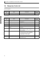
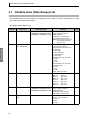
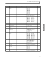
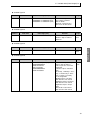
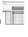
3.1 Variable Area (Data Range) List
The following tables list data ranges by variable type. When there is a section reference for a setting
item, refer to that reference for details.
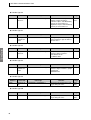
◆ Variable TypeC0 (Read-only)
Address
Data name
Data range (unit)
Remarks
Page
Timer PV
H'00000000 to H'0000270F (S)
H'00000000 to H'000026E7 (M:S)
H'00000000 to H'000026E7 (H:M)
Timer number specified by leftmost 2 digits of address.
00.00 to 99.99 s
00 min 00 s to 99 min 59 s
00 h 00 min to 99 h 59 min
Note: For twin timers, the PV of
the currently operating
timer is read.
P.18
0001
Timer type, time
unit, and monitor
H'00000000 to H'00420002 (-)
Timer number specified by leftmost 2 digits of address.
3rd Digit from Left: Timer Type
0: ON delay
1: OFF delay
2: One-shot pulse
3: Flashing pulse
4: Twin timer
4th Digit from Left: Time Unit
0: 0.01 s
1: M:S
2: H:M
8th Digit from Left: OFF Time
Unit (See note.)
0: 0.01s
1: M:S
2: H:M
Note: Twin timers only.
P.18
0002
Timer bit status
H'00000000 to H'0000FFFF (-)
Bit 0: T0
Bit 1: T1
Bit 2: T2
Bit 3: T3
Bit 4: T4
Bit 5: T5
Bit 6: T6
Bit 7: T7
---
0003
Holding timer PV
H'00000000 to H'0000270F (S)
H'00000000 to H'000026E7 (M:S)
H'00000000 to H'000026E7 (H:M)
Timer number specified by leftmost 2 digits of address.
00.00 to 99.99 s
00 min 00 s to 99 min 59 s
00 h 00 min to 99 h 59 min
P.18
0004
Holding timer time
unit
H'00000000 to H'00000002 (-)
Timer number specified by leftmost 2 digits of address.
0: 0.01 s
1: M:S
2: H:M
P.18
Com Data
0000
36
Bit 8: T8
Bit 9: T9
Bit 10: Ta
Bit 11: Tb
Bit 12: Tc
Bit 13: Td
Bit 14: Te
Bit 15: Tf
3.1 Variable Area (Data Range) List
Address
Data name
Data range (unit)
Remarks
Page
Holding timer bit
status
H'00000000 to H'000000FF (-)
Bit 0: #0
Bit 1: #1
Bit 2: #2
Bit 3: #3
Bit 4: #4
Bit 5: #5
Bit 6: #6
Bit 7: #7
---
0006
Counter PV
H'00000000 to H'0000270F (-)
Counter number specified by leftmost 2 digits of address.
P.18
0007
Counter bit status
H'00000000 to H'0000FFFF (-)
Bit 0: C0
Bit 1: C1
Bit 2: C2
Bit 3: C3
Bit 4: C4
Bit 5: C5
Bit 6: C6
Bit 7: C7
---
0008
8-digit counter PV
H'00000000 to H'05F5E0FF (-)
99999999 max.
P.19
0009
8-digit counter
counting speed
H'00000000 to H'00000001 (-)
0: Low speed
1: High speed
---
000A
8-digit counter bit
status
H'00000000 to H'00000001 (-)
Bit 0: F0
---
000B
Weekly timer operating mode
H'00000000 to H'00000002 (-)
Timer number specified by leftmost 2 digits of address.
0: Normal
1: Multiple-day
2: Pulse
P.23
000C
Weekly timer bit
status
H'00000000 to H'0000FFFF (-)
Bit 0: @0
Bit 1: @1
Bit 2: @2
Bit 3: @3
Bit 4: @4
Bit 5: @5
Bit 6: @6
Bit 7: @7
---
000D
Analog input value
H'00000000 to H'00000069 (V)
Analog number specified by leftmost 2 digits of address.
00: I4 (analog input 1)
01: I5 (analog input 2)
00.0 to 10.5 V
P.18
000E
Analog comparator
operator
H'00000000 to H'00000021 (-)
Comparator number specified by
leftmost 2 digits of address.
P.19
000F
Analog comparator
bit status
H'00000000 to H'0000000F (-)
Bit 0: A0
Bit 1: A1
Bit 2: A2
Bit 3: A3
---
0010
Comparator operator
H'00000000 to H'00000029 (-)
Comparator number specified by
leftmost 2 digits of address.
P.19
Bit 8: C8
Bit 9: C9
Bit 10: Ca
Bit 11: Cb
Bit 12: Cc
Bit 13: Cd
Bit 14: Ce
Bit 15: Cf
Bit 8: @8
Bit 9: @9
Bit 10: @a
Bit 11: @b
Bit 12: @c
Bit 13: @d
Bit 14: @e
Bit 15: @f
37
Com Data
0005
SECTION 3 Communications Data
Com Data
Address
Data name
Data range (unit)
Remarks
Bit 8: P8
Bit 9: P9
Bit 10: Pa
Bit 11: Pb
Bit 12: Pc
Bit 13: Pd
Bit 14: Pe
Bit 15: Pf
Page
0011
Comparator bit status
H'00000000 to H'0000FFFF (-)
Bit 0: P0
Bit 1: P1
Bit 2: P2
Bit 3: P3
Bit 4: P4
Bit 5: P5
Bit 6: P6
Bit 7: P7
---
0012
8-digit comparator
operator
H'00000008 to H'00000009 (-)
Comparator number specified by
leftmost 2 digits of address.
P.19
0013
CPU Unit output bit
status
H'00000000 to H'0000000F (-)
Bit 0: Q0
Bit 1: Q1
Bit 2: Q2
Bit 3: Q3 (use as work bit)
---
0014
CPU Unit input bit
status
H'00000000 to H'0000003F (-)
Bit 0: I0
Bit 1: I1
Bit 2: I2
Bit 3: I3
Bit 4: I4
Bit 5: I5
---
0015
Expansion I/O output bit status
H'00000000 to H'00000FFF (-)
Bits 0 to 3: Expansion 0, Y0 to Y3
Bits 4 to 7: Expansion 1, Y4 to Y7
Bits 8 to 11: Expansion 2, Y8 to
YB
---
0016
Expansion I/O input
bit status
H'00000000 to H'00000FFF (-)
Bits 0 to 3: Expansion 0, X0 to X3
Bits 4 to 7: Expansion 1, X4 to X7
Bits 8 to 11: Expansion 2, X8 to
XB
---
0017
8-digit comparator
bit status
H'00000000 to H'0000000F
Comparator number specified by
leftmost 2 digits of address.
Bit 0: G0
Bit 1: G1
Bit 2: G2
Bit 3: G3
---
Data range (unit)
Remarks
Page
• Timers Other Than Twin Timers
H'00000001 to H'0000270F (S)
H'00000001 to H'000026E7
(M:S)
H'00000001 to H'000026E7
(H:M)
• Twin Timers (See note.)
H'00010001 to H'270F270F (-)
Timer number specified by leftmost 2 digits of address.
00.01 to 99.99 s
00 min 01 s to 99 min 59 s
00 h 01 min to 99 h 59 min
◆ Variable Type C1
Address
0000
Data name
Timer SV
P.18
P.22
Note: The upper limit for twin timers depends on the time unit for the ON time and OFF time settings.
For min:s (M:S) or h:min (H:M), the upper limit is 26E7.
38
3.1 Variable Area (Data Range) List
◆ Variable Type C2
Address
0000
Data name
Holding time SV
Data range (unit)
Remarks
H'00000001 to H'0000270F (S)
H'00000001 to H'000026E7 (M:S)
H'00000001 to H'000026E7 (H:M)
Timer number specified by leftmost 2 digits of address.
00.01 to 99.99 s
00 min 01 s to 99 min 59 s
00 h 01 min to 99 h 59 min
Data range (unit)
Remarks
Page
P.18
◆ Variable Type C3
Address
0000
Data name
Counter SV
H'00000001 to H'0000270F (-)
Counter number specified by
leftmost 2 digits of address
9999 max.
Page
P.18
P.22
◆ Variable Type C4
Address
8-digit counter SV
Data range (unit)
H'00000001 to H'05F5E0FF (-)
Remarks
99999999 max.
Page
P.18
P.22
◆ Variable Type C5
Address
0000
Data name
Weekly timer SV
Data range
Normal or Multiple-day Operation
H’000000000000 to
H’006723592359
Pulse Operation
H’000000000000 to
H’006723599959
Remarks
Timer number specified by leftmost 2 digits of address.
Left 12 bytes are used in the
command.
Leftmost 4 Bytes: Start/End
Day
0: Sunday, 1: Monday, 2: Tuesday, 3: Wednesday, 4: Thursday, 5: Friday, 6: Saturday,
7: No designation
Middle 4 Bytes: Start Time
00 h 00 min to 23 h 59 min
Rightmost 4 Bytes: End Time
00 h 00 min to 23 h 59 min
Rightmost 4 Bytes: Output
Time
00 min 00 s to 99 min 59 s
00 h 01 min to 99 h 59 min
Page
P.18
P.23
39
Com Data
0000
Data name
SECTION 3 Communications Data
◆ Variable Type C6
Address
0000
Data name
Calendar
timer SV
Data range
H'01010101 to H'12311231 (-)
Remarks
Calendar timer number specified by
leftmost 2 digits of address.
Leftmost 4 Bytes: Start Month/Day
January 01 to December 31
Rightmost 4 Bytes: End Month/Day
January 01 to December 31
Page
P.18
P.25
◆ Variable Type C7
Address
0000
Data name
Analog comparator constant
Data range
H'00000000 to H'00000069 (V)
Remarks
Analog comparator number specified by leftmost 2 digits of address.
00.0 to 10.5 V
Page
P.19
Com Data
◆ Variable Type C8
Address
0000
Data name
Comparator
constant
Data range
H'00000000 to H'0000270F (-)
Remarks
Comparator number specified by
leftmost 2 digits of address.
T/#: 00.00 to 99.99
C: 0000 to 9999
Page
P.19
◆ Variable Type C9
Address
0000
Data name
8-digit comparator constant
Data range
H'00000000 to H'05F5E0FF (-)
Remarks
Comparator number specified by
leftmost 2 digits of address. (8-digit
comparator)
99999999 max.
Page
P.19
◆ Variable Type CA
Address
0000
Data name
Work bit status
Data range
H'00000000 to H'00000001 (-)
Remarks
Specify the bit position when reading or writing bit status.
Page
P.20
P.26
◆ Variable Type CB
Address
0000
40
Data name
HR bit status
Data range
H'00000000 to H'00000001 (-)
Remarks
Specify the bit position when reading or writing bit status.
Page
P.20
P.26
Appendix
ASCII List ................................................................................. 42
41
Appendix
ASCII List
b8
Appendix
Even parity
b8 b7 b6 b5
42
b7
0
0
0
0
1
1
1
1
b6
0
0
1
1
0
0
1
1
b5
0
1
0
1
0
1
0
1
0
1
2
3
4
5
6
7
C
b4
b3
b2
b1
0
0
0
0
0
NUL DLE SPACE
0
@
P
`
p
0
0
0
1
1
SOH DC1
!
1
A
Q
a
q
0
0
1
0
2
STX DC2
"
2
B
R
b
r
0
0
1
1
3
ETX DC3
#
3
C
S
c
s
0
1
0
0
4
EOT DC4
$
4
D
T
d
t
0
1
0
1
5
ENQ NAK
%
5
E
U
e
u
0
1
1
0
6
ACK SYN
&
6
F
V
f
v
0
1
1
1
7
BEL ETB
'
7
G
W
g
w
1
0
0
0
8
BS
CAN
(
8
H
X
h
x
1
0
0
1
9
HT
EM
)
9
I
Y
i
y
1
0
1
0
A
LF
SUB
*
:
J
Z
j
z
1
0
1
1
B
VT
ESC
+
;
K
[
k
{
1
1
0
0
C
FF
FS
,
<
L
\
l
|
1
1
0
1
D
CR
GS
-
=
M
]
m
}
1
1
1
0
E
SO
RS
.
>
N
^
n
~
1
1
1
1
F
SI
US
/
?
O
_
o
DEL
R
INDEX
INDEX
A
O
addresses ................................................................... 14
analog comparator .................................................... 18
ASCII list .................................................................. 42
operation command ...................................................32
B
parity ............................................................................5
PDU structure ............................................................14
pulse operation ..........................................................23
BCC .......................................................................... 10
BCC calculation example ......................................... 11
bit position .......................................................... 16, 21
C
calendar timer ........................................................... 25
changing from RUN Mode to STOP Mode ................ 5
command frame ........................................................ 10
command text ........................................................... 10
communications baud rate .......................................... 4
communications data .......................................... 12, 35
communications data length ....................................... 5
communications methods ........................................... 2
communications parameters ....................................... 4
communications specifications ................................... 2
comparator ................................................................ 19
CompoWay/F ............................................................. 9
D
data format ................................................................ 10
echoback test ............................................................ 31
eight-digit comparator .............................................. 18
end code .................................................................... 11
end code example ..................................................... 12
ETX .......................................................................... 10
I
interface ...................................................................... 3
K
K3SC .......................................................................... 3
L
list of services ........................................................... 15
M
MRC (Main Request Code) ...................................... 14
MRES (Main Response Code) ................................. 14
multi-day operation .................................................. 23
N
node number ......................................................... 4, 10
normal operation ....................................................... 23
number of elements .................................................. 14
R
read controller attributes ............................................26
read controller status .................................................27
read time data ............................................................28
read variable area ......................................................16
reading comparators ..................................................18
reading timers, counters, and comparators ................17
reading work bits and HR bits ...................................20
response code list ......................................................34
response frame ...........................................................11
RS-232C ......................................................................3
RS-485 communications submenu setting example ....6
S
Service Request PDU ................................................14
Service Response PDU ..............................................14
setting communications parameters ............................5
SID ............................................................................10
SRC (Sub-Request Code) ..........................................14
SRES (Sub-Response Code) .....................................14
stop bits .......................................................................5
structure of command text .........................................14
STX ...........................................................................10
sub-address ................................................................10
T
timer and counter number specifications ..................18
timer set values ..........................................................22
timer SV ....................................................................18
timer, counter, and comparator number specifications
....................................................................................23
transmission procedure ................................................3
twin timer ............................................................17, 22
V
variable area (data range) list ....................................36
W
weekly timer ..............................................................23
wiring ..........................................................................3
wiring diagram ............................................................4
write time data ...........................................................29
write variable area .....................................................21
writing work bits and HR bits ...................................26
43
Appendix
E
P
Terms and Conditions of Sale
1. Offer; Acceptance. These terms and conditions (these "Terms") are deemed
part of all quotes, agreements, purchase orders, acknowledgments, price lists,
catalogs, manuals, brochures and other documents, whether electronic or in
writing, relating to the sale of products or services (collectively, the "Products")
by Omron Electronics LLC and its subsidiary companies (“Omron”). Omron
objects to any terms or conditions proposed in Buyer’s purchase order or other
documents which are inconsistent with, or in addition to, these Terms.
2. Prices; Payment Terms. All prices stated are current, subject to change without notice by Omron. Omron reserves the right to increase or decrease prices
on any unshipped portions of outstanding orders. Payments for Products are
due net 30 days unless otherwise stated in the invoice.
3. Discounts. Cash discounts, if any, will apply only on the net amount of invoices
sent to Buyer after deducting transportation charges, taxes and duties, and will
be allowed only if (i) the invoice is paid according to Omron’s payment terms
and (ii) Buyer has no past due amounts.
4. Interest. Omron, at its option, may charge Buyer 1-1/2% interest per month or
the maximum legal rate, whichever is less, on any balance not paid within the
stated terms.
5. Orders. Omron will accept no order less than $200 net billing.
6. Governmental Approvals. Buyer shall be responsible for, and shall bear all
costs involved in, obtaining any government approvals required for the importation or sale of the Products.
7. Taxes. All taxes, duties and other governmental charges (other than general
real property and income taxes), including any interest or penalties thereon,
imposed directly or indirectly on Omron or required to be collected directly or
indirectly by Omron for the manufacture, production, sale, delivery, importation, consumption or use of the Products sold hereunder (including customs
duties and sales, excise, use, turnover and license taxes) shall be charged to
and remitted by Buyer to Omron.
8. Financial. If the financial position of Buyer at any time becomes unsatisfactory
to Omron, Omron reserves the right to stop shipments or require satisfactory
security or payment in advance. If Buyer fails to make payment or otherwise
comply with these Terms or any related agreement, Omron may (without liability and in addition to other remedies) cancel any unshipped portion of Products sold hereunder and stop any Products in transit until Buyer pays all
amounts, including amounts payable hereunder, whether or not then due,
which are owing to it by Buyer. Buyer shall in any event remain liable for all
unpaid accounts.
9. Cancellation; Etc. Orders are not subject to rescheduling or cancellation
unless Buyer indemnifies Omron against all related costs or expenses.
10. Force Majeure. Omron shall not be liable for any delay or failure in delivery
resulting from causes beyond its control, including earthquakes, fires, floods,
strikes or other labor disputes, shortage of labor or materials, accidents to
machinery, acts of sabotage, riots, delay in or lack of transportation or the
requirements of any government authority.
11. Shipping; Delivery. Unless otherwise expressly agreed in writing by Omron:
a. Shipments shall be by a carrier selected by Omron; Omron will not drop ship
except in “break down” situations.
b. Such carrier shall act as the agent of Buyer and delivery to such carrier shall
constitute delivery to Buyer;
c. All sales and shipments of Products shall be FOB shipping point (unless otherwise stated in writing by Omron), at which point title and risk of loss shall
pass from Omron to Buyer; provided that Omron shall retain a security interest in the Products until the full purchase price is paid;
d. Delivery and shipping dates are estimates only; and
e. Omron will package Products as it deems proper for protection against normal handling and extra charges apply to special conditions.
12. Claims. Any claim by Buyer against Omron for shortage or damage to the
Products occurring before delivery to the carrier must be presented in writing
to Omron within 30 days of receipt of shipment and include the original transportation bill signed by the carrier noting that the carrier received the Products
from Omron in the condition claimed.
13. Warranties. (a) Exclusive Warranty. Omron’s exclusive warranty is that the
Products will be free from defects in materials and workmanship for a period of
twelve months from the date of sale by Omron (or such other period expressed
in writing by Omron). Omron disclaims all other warranties, express or implied.
(b) Limitations. OMRON MAKES NO WARRANTY OR REPRESENTATION,
EXPRESS OR IMPLIED, ABOUT NON-INFRINGEMENT, MERCHANTABIL-
14.
15.
16.
17.
18.
ITY OR FITNESS FOR A PARTICULAR PURPOSE OF THE PRODUCTS.
BUYER ACKNOWLEDGES THAT IT ALONE HAS DETERMINED THAT THE
PRODUCTS WILL SUITABLY MEET THE REQUIREMENTS OF THEIR
INTENDED USE. Omron further disclaims all warranties and responsibility of
any type for claims or expenses based on infringement by the Products or otherwise of any intellectual property right. (c) Buyer Remedy. Omron’s sole obligation hereunder shall be, at Omron’s election, to (i) replace (in the form
originally shipped with Buyer responsible for labor charges for removal or
replacement thereof) the non-complying Product, (ii) repair the non-complying
Product, or (iii) repay or credit Buyer an amount equal to the purchase price of
the non-complying Product; provided that in no event shall Omron be responsible for warranty, repair, indemnity or any other claims or expenses regarding
the Products unless Omron’s analysis confirms that the Products were properly handled, stored, installed and maintained and not subject to contamination, abuse, misuse or inappropriate modification. Return of any Products by
Buyer must be approved in writing by Omron before shipment. Omron Companies shall not be liable for the suitability or unsuitability or the results from the
use of Products in combination with any electrical or electronic components,
circuits, system assemblies or any other materials or substances or environments. Any advice, recommendations or information given orally or in writing,
are not to be construed as an amendment or addition to the above warranty.
See http://oeweb.omron.com or contact your Omron representative for published information.
Limitation on Liability; Etc. OMRON COMPANIES SHALL NOT BE LIABLE
FOR SPECIAL, INDIRECT, INCIDENTAL, OR CONSEQUENTIAL DAMAGES,
LOSS OF PROFITS OR PRODUCTION OR COMMERCIAL LOSS IN ANY
WAY CONNECTED WITH THE PRODUCTS, WHETHER SUCH CLAIM IS
BASED IN CONTRACT, WARRANTY, NEGLIGENCE OR STRICT LIABILITY.
Further, in no event shall liability of Omron Companies exceed the individual
price of the Product on which liability is asserted.
Indemnities. Buyer shall indemnify and hold harmless Omron Companies and
their employees from and against all liabilities, losses, claims, costs and
expenses (including attorney's fees and expenses) related to any claim, investigation, litigation or proceeding (whether or not Omron is a party) which arises
or is alleged to arise from Buyer's acts or omissions under these Terms or in
any way with respect to the Products. Without limiting the foregoing, Buyer (at
its own expense) shall indemnify and hold harmless Omron and defend or settle any action brought against such Companies to the extent based on a claim
that any Product made to Buyer specifications infringed intellectual property
rights of another party.
Property; Confidentiality. Any intellectual property in the Products is the exclusive property of Omron Companies and Buyer shall not attempt to duplicate it
in any way without the written permission of Omron. Notwithstanding any
charges to Buyer for engineering or tooling, all engineering and tooling shall
remain the exclusive property of Omron. All information and materials supplied
by Omron to Buyer relating to the Products are confidential and proprietary,
and Buyer shall limit distribution thereof to its trusted employees and strictly
prevent disclosure to any third party.
Export Controls. Buyer shall comply with all applicable laws, regulations and
licenses regarding (i) export of products or information; (iii) sale of products to
“forbidden” or other proscribed persons; and (ii) disclosure to non-citizens of
regulated technology or information.
Miscellaneous. (a) Waiver. No failure or delay by Omron in exercising any right
and no course of dealing between Buyer and Omron shall operate as a waiver
of rights by Omron. (b) Assignment. Buyer may not assign its rights hereunder
without Omron's written consent. (c) Law. These Terms are governed by the
law of the jurisdiction of the home office of the Omron company from which
Buyer is purchasing the Products (without regard to conflict of law principles). (d) Amendment. These Terms constitute the entire agreement between
Buyer and Omron relating to the Products, and no provision may be changed
or waived unless in writing signed by the parties. (e) Severability. If any provision hereof is rendered ineffective or invalid, such provision shall not invalidate
any other provision. (f) Setoff. Buyer shall have no right to set off any amounts
against the amount owing in respect of this invoice. (g) Definitions. As used
herein, “including” means “including without limitation”; and “Omron Companies” (or similar words) mean Omron Corporation and any direct or indirect
subsidiary or affiliate thereof.
Certain Precautions on Specifications and Use
1. Suitability of Use. Omron Companies shall not be responsible for conformity
with any standards, codes or regulations which apply to the combination of the
Product in the Buyer’s application or use of the Product. At Buyer’s request,
Omron will provide applicable third party certification documents identifying
ratings and limitations of use which apply to the Product. This information by
itself is not sufficient for a complete determination of the suitability of the Product in combination with the end product, machine, system, or other application
or use. Buyer shall be solely responsible for determining appropriateness of
the particular Product with respect to Buyer’s application, product or system.
Buyer shall take application responsibility in all cases but the following is a
non-exhaustive list of applications for which particular attention must be given:
(i) Outdoor use, uses involving potential chemical contamination or electrical
interference, or conditions or uses not described in this document.
(ii) Use in consumer products or any use in significant quantities.
(iii) Energy control systems, combustion systems, railroad systems, aviation
systems, medical equipment, amusement machines, vehicles, safety equipment, and installations subject to separate industry or government regulations.
(iv) Systems, machines and equipment that could present a risk to life or property. Please know and observe all prohibitions of use applicable to this Product.
NEVER USE THE PRODUCT FOR AN APPLICATION INVOLVING SERIOUS
RISK TO LIFE OR PROPERTY OR IN LARGE QUANTITIES WITHOUT
ENSURING THAT THE SYSTEM AS A WHOLE HAS BEEN DESIGNED TO
2.
3.
4.
5.
ADDRESS THE RISKS, AND THAT THE OMRON’S PRODUCT IS PROPERLY RATED AND INSTALLED FOR THE INTENDED USE WITHIN THE
OVERALL EQUIPMENT OR SYSTEM.
Programmable Products. Omron Companies shall not be responsible for the
user’s programming of a programmable Product, or any consequence thereof.
Performance Data. Data presented in Omron Company websites, catalogs
and other materials is provided as a guide for the user in determining suitability and does not constitute a warranty. It may represent the result of Omron’s
test conditions, and the user must correlate it to actual application requirements. Actual performance is subject to the Omron’s Warranty and Limitations
of Liability.
Change in Specifications. Product specifications and accessories may be
changed at any time based on improvements and other reasons. It is our practice to change part numbers when published ratings or features are changed,
or when significant construction changes are made. However, some specifications of the Product may be changed without any notice. When in doubt, special part numbers may be assigned to fix or establish key specifications for
your application. Please consult with your Omron’s representative at any time
to confirm actual specifications of purchased Product.
Errors and Omissions. Information presented by Omron Companies has been
checked and is believed to be accurate; however, no responsibility is assumed
for clerical, typographical or proofreading errors or omissions.
OMRON ELECTRONICS LLC
1 Commerce Drive
Schaumburg, IL 60173
847.843.7900
For US technical support or
other inquiries: 800.556.6766
OMRON CANADA, INC.
885 Milner Avenue
Toronto, Ontario M1B 5V8
416.286.6465
OMRON ON-LINE
Global - http://www.omron.com
USA - http://www.omron.com/oei
Canada - http://www.omron.ca
Z212-E1-01
10/06
©2006 OMRON ELECTRONICS LLC
Printed in the U.S.A.
Specifications subject to change without notice.