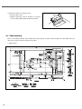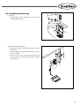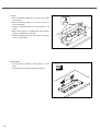
1
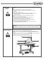
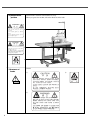
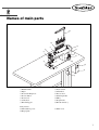
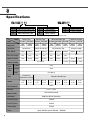
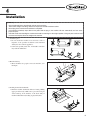
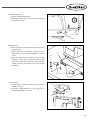
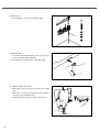
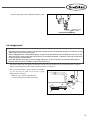
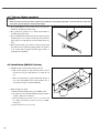
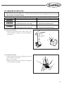
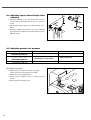
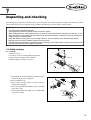
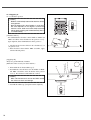
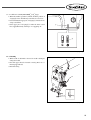
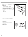
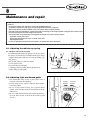
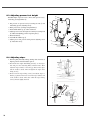
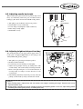
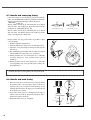
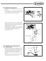
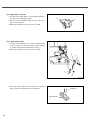
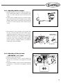
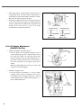
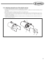
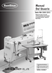
R
USER ’
S
MANUAL
KM-2300
KM-2300 2310
SeriesSeries
Direct Drive, High Speed,
1-Needle Lock Stitch Machine
with an Automatic Thread Trimmer
SUNSTAR MACHINERY CO., LTD.
1) FOR AT MOST USE WITH EASINESS,
PLEASE CERTAINLY READ THIS MANUAL
BEFORE STARTING USE.
2) KEEP THIS MANUAL IN SAFE PLACE
FOR REFERENCE WHEN THE MACHINE
BREAKS DOWN.
MME-050627
lity
a
u
tQ
Besst Pricevice
Be st Ser
Be
1. Thank you for purchasing our product. Based on the rich expertise and
experience accumulated in industrial sewing machine production, SUNSTAR
will manufacture industrial sewing machines, which deliver more diverse
functions, high performance, powerful operation, enhanced durability, and
more sophisticated design to meet a number of user’s needs.
2. Please read this user’s manual thoroughly before using the machine. Make
sure to properly use the machine to enjoy its full performance.
3. The specifications of the machine are subject to change, aimed to enhance
product performance, without prior notice.
4. This product is designed, manufactured, and sold as an industrial sewing
machine. It should not be used for other than industrial purpose.
R
SUNSTAR MACHINERY CO., LTD.
CONTENTS
1. Machine safety regulations ……………………………………………………………
1-1. Transporting machine………………………………………………………………………
1-2. Installing machine …………………………………………………………………………
1-3. Repairing machine …………………………………………………………………………
1-4. Operating machine …………………………………………………………………………
1-5. Safety devices ………………………………………………………………………………
1-6. Caution mark position ………………………………………………………………………
1-7. Contents of marks …………………………………………………………………………
4
4
4
4
5
5
6
6
2. Names of main parts ……………………………………………………………………
7
3. Specifications ……………………………………………………………………………
8
4. Installation …………………………………………………………………………………
4-1. Table drawing ………………………………………………………………………………
4-2. Installing machine body ……………………………………………………………………
4-3. Supplying oil ………………………………………………………………………………
4-4. Trial run (Pedal operation) …………………………………………………………………
4-5. Installation (KM-2310 Series) ………………………………………………………………
9
10
11
15
16
16
5. Preparations for sewing …………………………………………………………………
5-1. Installing needle ……………………………………………………………………………
5-2. Removing bobbin case………………………………………………………………………
5-3. Winding lower thread ………………………………………………………………………
5-4. Installing bobbin case ………………………………………………………………………
5-5. Inserting upper thread ………………………………………………………………………
5-6. Using knee lifter pad ………………………………………………………………………
17
17
17
18
18
19
19
6. Sewing ……………………………………………………………………………………
6-1. Sewing………………………………………………………………………………………
6-2. Back tack (reverse) sewing …………………………………………………………………
6-3. Adjusting thread tension ……………………………………………………………………
6-3-1. Lower thread tension …………………………………………………………………
6-3-2. Upper thread tension …………………………………………………………………
6-4. Adjusting upper thread length after trimming ………………………………………………
6-5. Adjusting presser foot pressure………………………………………………………………
6-5-1. Presser foot pressure …………………………………………………………………
20
20
20
21
21
21
22
22
22
7. Inspecting and checking ……………………………………………………………… 23
7-1. Daily cleaning ………………………………………………………………………………
7-1-1. Cleaning ……………………………………………………………………………
7-1-2. Supplying oil…………………………………………………………………………
7-1-2-1. Oil flow in gear box ………………………………………………………
7-1-2-2. Oil flow in oil tank (KM-2300M & S Type) …………………………
7-1-3. Checking ……………………………………………………………………………
7-2. Supplying grease (KM-2300S & F ) ……………………………………………………
23
23
24
24
25
25
26
8. Maintenance and repair …………………………………………………………………
8-1. Adjusting thread take-up spring ……………………………………………………………
8-1-1. Position of thread take-up spring ……………………………………………………
8-2. Adjusting right arm thread guide ……………………………………………………………
8-3. Adjusting presser foot height ………………………………………………………………
8-4. Adjusting wiper ……………………………………………………………………………
8-5. Adjusting needle bar height …………………………………………………………………
8-6. Adjusting height and slope of feed dog………………………………………………………
8-7. Needle and conveying timing ………………………………………………………………
8-8. Needle and hook timing ……………………………………………………………………
8-9. Adjusting trimming time ……………………………………………………………………
8-10. Adjusting and replacing knife………………………………………………………………
8-10-1. Adjusting fixed knife ………………………………………………………………
8-10-2. Replacing movable knife ……………………………………………………………
8-10-3. Replacing fixed knife ………………………………………………………………
8-11. Adjusting bobbin stopper …………………………………………………………………
8-12. Adjusting oil flow in hook (KM-2300M & S type) ……………………………………
8-13. Oil Supply Adjustment (KM-2310 Series) …………………………………………………
8-14. Adjusting automatic knee lifter (Option device) ……………………………………………
27
27
27
27
28
28
29
29
30
30
31
31
31
32
32
33
33
34
35
9. Causes of troubles and troubleshooting …………………………………………… 36
1
Machine safety regulations
Safety instructions on this manual are defined as Danger, Warning and Notice.
If you do not follow the instructoins, physical injuries and machine damages might be occurred.
Danger : This indication should be observed definitely. If not, there will be a danger during the installation,
conveyance and maintenance of the machine.
:
Warning When you follow this indication, injuries from the machine can be prevented.
Notice : When you follow this indication, error on the machine can be prevented.
1-1) Transporting
machine
Those in charge of transporting the machine should have a full understanding of the
machine. The following indications should be followed when the machine is being
transported.
ⓐ More than 2 people must transport the machine.
ⓑ To prevent accidents from occurring during transportation, wipe off the oil
on the machine compeletely.
Danger
1-2) Installing
machine
Warning
The machine may not work properly or breakdown, if installed in certain places, Install the
machine where the following qualifications agree.
ⓐ Remove the package and wrappings from the top. Take special
notice on the nails on the wooden boxes.
ⓑ Dust and moisture stains and rusts the machine. Install an airconditioner
and clean the machine regularly.
ⓒ Keep the machine out of the sun.
ⓓ Leave sufficient space of more than 50cm behind, and on the right and left
side of the machine for repairing.
ⓔ EXPLOSION HAZARDS
Do not operate in explosive atmospheres. To avoid explosion, do not operate
this machine in an explosive atomsphere including a place where large
quantities of aerosol spray product are being used or where oxygen is being
administered unless it has been specifically certified for such operation.
ⓕ The machine is not provided with a local lighting due to the feature of
machine.
Therefore the illumination of the working area must be fulfilled by end user.
[Refer] Details for machine installation are described in 4. Installation.
1-3) Repairing
machine
Notice
4
When the machine needs to be repaired, only the assigned troubleshooting engineer
educated at the company should take charge.
ⓐ Before cleaning or repairing the machine, turn off the main power
and wait 4 minutes till the machine is completely out of power.
ⓑ Not any of the machine specifications or parts should be changed
without consulting the company.
Such changes may make the operation dangerous.
ⓒ Spare parts produced by the company should only be used for
replacements.
ⓓ Put all the safety covers back on the machine after the machine has been repaired.
1-4) Operating
machine
Warning
KM-2300 Series is made to sew patterns on fabrics and other similar materials for industrial
use.
Follow the following indications when operating the machine.
ⓐ Read through this manual carefully and completely before operating the
machine.
ⓑ Wear proper clothes for work.
ⓒ Keep hands or other parts of the body away from the machine’s operation
parts(needle, shuttle, thread take-up lever, pulley, etc.) when the
machine is operating.
ⓓ Keep the covers and finger guard on the machine during operation.
ⓔ Be sure to connect the earthing conductor.
ⓕ Turn off the main power and check if the switch is turned“off”
before opening electric boxes such as the control box.
ⓖ Stop the machine before threading the needle or checking after work.
ⓗ Do not step on the pedal when turning the power on.
ⓘ If possible, install the machine away from source of strong electrical noise
such as high frequency welding machines
[ Warning ]
Keep motor cover in place before operating, turn off power before inspecting or adjusting.
1-5) Safety devices
Notice
ⓐ Safety label : It describes cautions during the machine operation.
ⓑ Thread take-up cover : It prevents any contact between body and take-up lever.
ⓒ Motor cover : A device to prevent hands, feet and clothing from getting jammed by the
motor.
ⓓ Label for specification of power : It describes cautions for safety to protect electric shock
during the motors’ rotation. (Voltage input / use Hz)
ⓔ Finger guard : It prevent contacts between finger and needle.
ⓐ
ⓑ
ⓒ
ⓔ
ⓓ
5
1-6) Caution mark
position
Caution mark is attached on the machine for safety.
When you operate the machine, follow the directions on the mark.
CAUTION
주 의
Do not operate without finger guard and
safety devices. Before threading, changing
bobbin and needle, cleaning etc. switch off
main switch.
손가락 보호대와 안전장치 없이 작동하지
마십시오.
실, 보빈, 바늘교환시나 청소전에는 반드시 주
전원의 스위치를 꺼 주십시오.
WARNING
경 고
Hazardous voltage will cause injury.
Be sure to wait at least 360 seconds before
opening this cover after turn off main switch
and unplug a power cord.
고압 전류에 의해 감전될 수 있으므로 커버를
열 때는 전원을 내리고 전원 플러그를 뽑고 나
서 360초간 기다린 후 여십시오.
1-7)Contents of
marks
Caution
1)
CAUTION
주 의
Do not operate without finger guard
and safety devices. Before threading,
changing bobbin and needle, cleaning
etc. switch off main switch.
Warning
손가락 보호대와 안전장치 없이 작동하지 마
십시오.
실, 보빈, 바늘교환시나 청소전에는 반드시
주전원의 스위치를 꺼 주십시오.
2)
WARNING
경 고
Hazardous voltage will cause injury.
Be sure to wait at least 360 seconds
before opening this cover after turn
off main switch and unplug a power
cord.
고압 전류에 의해 감전될 수 있으므로 커버
를 열 때는 전원을 내리고 전원 플러그를 뽑
고 나서 360초간 기다린 후 여십시오.
6
3)
2
Names of main parts
⑭
⑬
⑫
①
②
⒔
③
⑪
⑮
⑤
④
⑩
⑨
⑧
⒃
⑥
⑦
① Bobbin winder
② Wiper
③ Presser bar lifting lever
④ Reverse button
⑤ Presser foot
⑥ Control box
⑦ Knee lifting pad
⑧ Power switch
⑨ Oil window
⑩ Reverse lever
⑪ Stitch length dial
⑫ Pulley
⑬ Program unit
⑭ Thread stand ass’y
Safety Devices
⑮ Thread take-up cover
⒃ Finger guide
⒔ Motor cover
7
3
Specifications
KM-2300
KM-2310
Code
Lubrication type
F
Full Dry(No-Lubrication Type)
S
Semi Dry(needle bar No-Lubrication Type)
M
Micro-Lubrication Type
Code
G
B
Application
Code
A
G
B
Light materials
General materials
Heavy materials
Application
General materials
Heavy materials
The “B”(Heavy Material) code can be used at the “M”(micro oil supply)-type sewing machine only.
Model
Full-Dry Type
Semi-Dry Type
Automatic oil supply
Spec.
KM-2300FA KM-2300FG KM-2300SA KM-2300SG KM-2300MA KM-2300MG KM-2300MB
KM-2310G
KM-2310B
Application
Light
materials
General
materials
Heavy
materials
Lubrication
General
materials
No-Lubrication
Light
materials
General
materials
General
materials
Light
materials
Needle Bar No-Lubrication
Heavy
materials
Micro-Lubrication Type
3,500spm
4,000spm
4,000spm
5,000spm
4,000spm
5,000spm
4,500spm
Max. Stitch Length
4mm
5mm
4mm
5mm
4mm
5mm
5mm
Needle Bar Stroke
29mm
30.7mm
29mm
30.7mm
29mm
30.7mm
33.4mm
Max. Speed
By Hand
Lift of
Presser By Knee
Foot
Auto
DB×1 SF(KN)#11
#9~#11
Main Motor
30.7mm
33.4mm
1~1.2mm
DB×1#14
#11~#18
Automatic Lubrication Hook
DB×1 SF(KN)#11
#9~#11
DB×1#14
#11~#18
DB×1 SF(KN)#11
#9~#11
DB×1#14
#11~#18
DB×1#21
#19~#23
300mm
517mm × 178mm
Built-in the Machine Head
500W Direct Drive AC Servo Motor
Automatic BackTack Device
Provided
Automatic Thread Trimmer
Provided
Thread Wiper
Provided
Power
5mm
15mm (Option)
Needle
Bobbin Winder
4,500spm
15mm
No-Lubrication Hook
(Engineering Plastic Coated Race)
Bed Size
5,000spm
5.5mm
Hook
Working Space
Automatic oil supply
1~1.2mm 0.75~0.85mm
0.75~0.85mm
Height of Feed Dog
8
Micro-Lubrication Type
1-phase: 100~240V, 3-phase: 200~240V 50Hz/60Hz
DB×1#14
#11~#18
DB×1#21
#19~#23
4
Installation
[ Caution ]
·Only trained technicians should install and wire up the machine.
·The machine weighs over 50 kg. More than two persons should install the machine.
·Do not plug in the machine until installation is completed.
If the operator mistakenly steps down on the pedal with the plug in, the machine will start automatically and can cause
physical injuries.
·Use both hands when bending the machine backwards or returning it to the original position. Using only one hand can lead
to severe hand injuries due to the weight of the machine.
1. Installation place
1) Do not install the machine near television, radio or
telephone; or the operation of machine can be interfered
with by the noise from the appliances.
2) Connect the ground (earth) wire. An unstable connection
may result in malfunction
[ Figure 1 ]
2. Machine delivery
1) There should be two people to move the machine, as in
the Figure.
[ Figure 2 ]
3. Bending the machine backwards
1) Bend the machine backwards with two hands grabbing
upper part of the body. Make sure to press the lower part
of the board leg of the machine, or the whole body of
machine falls backwards, leading to physical injuries.
[ Figure 3 ]
9
4. Return the machine to its original position
1) Clear the table of tools.
2) With the right hand, return the machine to its original
position, while grabbing sideboard with the left hand.
[ Figure 4 ]
4-1. Table drawing
Please use the table provided by Sunstar. When using self-made table , the thick of table should be more than 40mm. Please use
table strong enough to sustain the weight of the machine.
1. Table Drawing
[ Figure 5 ]
10
4-2. Installing machine body
1. Control box
1) As in the Figure, attach control box ① to the lower part
of table with four bolts ②.
②
①
[ Figure 6 ]
2. Pedal switch and connecting rod
1) Attach pedal switch ① to pedal switch bracket ② with
four bolts ③.
2) As in the Figure, attach pedal switch bracket ② to the
lower part of table.
3) Connect one end of the connecting rod ④ with pedal
switch and the other end with pedal, and then adjust
length of the rod.
③
①
②
④
[ Figure 7 ]
11
3. Oil Pan
1) Fix two head hinge rubber (B) ① to the rear side of table
with nails ④.
2) Fix two head hinge rubber (A) ② to the front side of
table with nails ④.
3) Insert four head hinge rubber (c) ③ into four holes of oil
pan⑤.
4) Place safely oil pan ⑤ assembled with cushion rubbers
into the rectangular hole on the table.
5) Insert knee lifting support cap ⑥ into oil pan’s projecting
hole ⑦ as in the figure.
③
⑤
④
①
④
②
[ Figure 8 ]
4. Hinge Rubber
1) As in the figure, assemble two-hinge rubbers ① on the
table.
2) As in the figure, fix the hinge rubbers with nails ②.
① ②
②
①
[ Figure 9 ]
12
5. Deflation Bushing cap
1) Remove deflation-bushing cap①.
2) If deflation-bushing cap① is not removed, oil may spill
from gearbox cover②.
①
②
[ Figure 10 ]
6. Machine body
1) Insert two hinges ① firmly into the holes of the rear side
of machine bed.
2) Put machine body on the rubber cushion ③, while
putting hinges ① on the hinge bed rubber ② safe and
sound.
3) Insert the machine body sustaining pole ④ into table
completely. If the pole is not inserted completely, that
may cause accidents because the pole cannot sustain the
weight of machine body firmly, when the body bent
backwards.
③
④
①
②
[ Figure 11 ]
7. Program Unit
1) As in the Figure, combine program unit ① to bracket ③
with three screws ②.
2) Attach the combined bracket ③ to the upper part of
machine body with three screws ④.
①
②
③
④
[ Figure 12 ]
13
8. Thread stand
1) As in the Figure, fix the thread stand① to table.
①
[ Figure 13 ]
9. Knee Lifter Pad
1) As in the figure, attach knee lifter pad① to the lower part
of oil pan. And then fix it with bolt②.
2) Loosen bolt③ to adjust position of knee lifter pad①.
③
②
①
[ Figure 14 ]
10. Adjusting height of Presser Foot
1) Turn pulley to place feed dog in the lower part of needle
plate.
2) When presser foot① is up, make presser foot① down by
lowering presser bar lifting lever②.
3) Adjust the position of presser foot① by using screw③.
②
③
①
[ Figure 15 ]
14
4) The standard height is 10mm. Maximum height is 15mm.
Standard 10 mm
(Max. 15mm)
[ Figure 16 ]
4-3. Supplying oil
[ Caution ]
·Plug in only after oil supply is finished. If the operator mistakenly steps on the pedal with the plug in, the machine will start
automatically and can cause severe injuries.
·When handling lubricants, wear protective glasses or gloves to prevent lubricants from contacting with your eyes or skin.
Wash your hands in running water with soap when they are smeared with lubricant. If lubricant is in the eye, instantly wash
it with running water and see a doctor.
·Never drink lubricants since they can cause vomiting or diarrhoea. Go to see a doctor, if you mistakenly drink lubricant.
·Keep the oil out of the reach of children. Keep the oil away from heat.
·Operate the machine only after supplying oil when the machine is used for the first time or has been left unused for a long time.
·Only use genuine lubricant of this company. (Lubricant is in the accessory box.)
1. Turn over sewing machine, seperates oil holes ② and rubber
cap. Use the oil can ① inthe accessory box to supply
lubricant into the oil holes②.
※ Make sure not to pour the whole lubricant.
Pour oil to Max position of lubrication tank③.
①
②
③
[ Figure 17 ]
15
4-4. Trial run (Pedal operation)
[ Caution ]
·Make sure not to touch or press down parts that are operating or moving during operation. Failure to follow the safety rules
may result in physical injuries or mechanical damages.
1. Press pedal lightly to the position of B to check if the
machine is operating low-speed sewing.
2. Press pedal to the position of C to check if the machine is
operating high-speed sewing.
3. Press pedal backward and forward. And then put the pedal at
neutral position of A to check if needle stops lower than the
upper surface of needle plate.(in case that needle down stop
is set)
4. When pressing pedal to the position of D(or pressing pedal
the position of to D and then replacing pedal to the position
of A), needle will stop higher than the upper surface of
needle plate after trimming.
[ Figure 18 ]
4-5. Installation (KM-2310 Series)
1. Installing magnet for chip (metal powder) removal
1) Take out the magnet for chip (metal powder) removal
from the accessory box and attach it to ① inside the oil
fan.
①
※ If the sewing machine is operated without the magnet, it
may cause abnormalities in the sewing machine. Use of
the magnet can improve machine durability.
2. Lubricant supply to oil fan
1) Fill the oil fan with lubricant up to the “HIGH” mark.
2) Use either the oil for SunStar industrial sewing machines
or Shell’
s Tellus C10 as lubricant.
3) When the lubricant level falls to “Low”, the oil fan shall
be refilled with lubricant until it reaches the “HIGH”
mark again.
4) Replace lubricant every two weeks.
16
[ Figure 19 ]
5
Preparations for sewing
5-1. Installing needle
[ Caution ]
·Always turn off the power when mounting a needle.
If the operator mistakenly steps on the pedal while the power is on, the machine will start automatically and can result in
physical injuries.
1. Turn the pulley of machine to raise needle bar to its highest
position.
2. Unfasten the fixing screw ①.
3. As in the figure, insert needle ② straight to the end with the
needle’s long groove facing left and fasten the fixing screw
① firmly.
Worker’s
side
①
②
Needle’s
long
groove
[ Figure 20 ]
5-2. Removing bobbin case
[ Caution ]
·Always turn off the power when removing a bobbin case.
If the operator mistakenly steps on the pedal while the power is on, the machine will start automatically and can result in
physical injuries.
1. Place needle at the upper part of needle plate by turning
pulley.
2. Remove bobbin case by pulling bobbin case holder ①.
3. Let go of the holder ① to remove bobbin ②.
4. The spring ③ inside bobbin case is designed to prevent
bobbin from spinning idly during trimming.
①
②
③
[ Figure 21 ]
17
5-3. Winding lower thread
[ Caution ]
·Make sure not to touch or press down parts that are operating or moving during thread winding. Failure to follow the safety
rules may result in physical injuries or mechanical damages.
1. Turn on the power switch.
2. Insert bobbin① into bobbin winder shaft②.
3. Wind thread on bobbin① several times in the arrow
direction.
4. Push bobbin lever③ in the direction of bobbin.
5. Raise presser bar with presser bar lifter.
6. When pressing pedal, the machine starts to operate and
thread winds on bobbin.
7. When thread winding is done, bobbin lever③ returns
automatically.
8. Remove bobbin and cut thread with bobbin winder knife④.
※ To adjust the amount of bobbin winding, loosen screw⑤
and adjust bobbin winder adjusting plate③.
④
①
③
②
③
⑥
⑤
[ Caution ]
Make sure that thread should be regulated to wind 80%
of bobbin capacity.
80%
[ Figure 22 ]
5-4. Installing bobbin case
[ Caution ]
·When installing bobbin case, make sure to turn off the power. Pressing pedal by mistake may result in physical injuries or
mechanical damages.
1. Turn pulley to place needle at the upper part of needle plate.
2. Wind thread on bobbin to the right and insert it into bobbin
case.
3. Pass thread through groove① and then pass it through the
lower part of tension spring②.
4. Pull thread out of the thread hole at the end of tension spring
②.
5. Pull thread to make sure that bobbin moves to the right as in
the figure.
6. After pulling the holder of bobbin case③, install bobbin case
into hook.
①
②
③
[ Figure 23 ]
18
5-5. Inserting upper thread
[ Caution ]
·Always turn off the power when inserting upper thread.
If the operator mistakenly steps on the pedal while the power is on, the machine will start automatically and can result in
physical injuries.
1. Place the thread take-up ① at its the highest position by
turning pulley before inserting the upper thread, so that it
becomes easy to insert it and prevent it from falling out
when the machine starts to operate.
2. The adequate length of upper thread extending from the
needle hole is 35 ~ 40mm.
①
[ Figure 24 ]
5-6. Using knee lifer pad
1. Pressing knee lifter pad① to the right will move presser foot
② up and down.
①
②
[ Figure 25 ]
19
6
Sewing
[ Caution ]
·Wear protective gears for safety. Operation without them may lead to physical injuries.
·Turn off the machine in the following situations.
If the operator mistakenly steps on the pedal with the plug in, the machine will start automatically and can cause severe
injuries.
·When inserting upper thread
·When replacing bobbin or needle
·When the machine not in use or the operator leaving the work place.
6-1. Sewing
1. Press ON button of power switch ①.
2. Lamp on the program unit ② turns on and machine is ready
to operate.
3. Control sewing conditions by using program unit ②.
(See user’s manual of Fortuna IV.)
4. Step on the pedal to operate.
②
①
[ Figure 26 ]
6-2. Back tack (reverse) sewing
1. Pressing the reverse switch ① or reverse lever ② will move
sewing material backward. Sewing material will go forward
if either of them is not being pressed.
①
②
[ Figure 27 ]
20
6-3. Adjusting thread tension
[ Caution ]
·When inserting and removing bobbin case, make sure to turn off the power switch. Pressing pedal by mistake may result
in physical injuries or mechanical damages.
Sewing Type
Cause
Troubleshooting
Good sewing in balance
Upper thread tension is too weak
Make upper thread tension strong or
Lower thread tension is too strong
make lower thread tension weak
Upper thread tension is too strong
Make upper thread tension weak or
Lower thread tension is too weak
make lower thread tension strong
6-3-1. Lower thread tension
1. Adjust tension by turning tension control screw① to the
extent that bobbin case falls by gravity when holding the
end of thread.
①
Strong
Weak
[ Figure 28 ]
6-3-2. Upper thread tension
1. Adjust upper thread tension after adjusting lower thread
tension to make sure good sewing.
2. Move presser foot down.
3. Adjust upper thread tension by turning tension-adjusting
screw② of main thread controller.
②
Weak
Strong
[ Figure 29 ]
21
6-4. Adjusting upper thread length after
trimming
1. During the trimming process, main thread release tension is
not created but only auxiliary thread release ① tension is
created.
2. The adequate length of upper thread after trimming is 35 ~
40mm.
3. Increasing auxiliary thread release ① tension will make
upper thread after trimming short and decreasing the tension
will make it long.
①
[ Figure 30 ]
6-5. Adjusting presser foot pressure
Sewing style
Causes
Corrective action
Good sewing in balance
A stitch is skipped
Stitch lengths are not uniform
Puckering
6-5-1 Presser foot pressure
1. Make the presser foot pressure as weak as possible.
(But as weak as for sewing material not to slide.)
2. Unfasten the pressure adjusting nut ①.
3. Turn the pressure adjusting screw ② to adjust presser foot
pressure.
4. Fasten the pressure adjusting nut ①.
Increase pressure
Decrease pressure
②
①
[ Figure 31 ]
22
7
Inspecting and checking
To maintain proper performance of machine and use it for a long time, clean machine regularly according to the following way. Evan
when machine is not in use for a long time, clean according to the following way before using the sewing machine.
[ Caution ]
·Turn off the power switch before operation.
Pressing pedal by mistake may operate machine and result in injuries.
·When handling lubricants, wear protective glasses or gloves to prevent lubricant from contacting with your eyes or skin.
Wash your hands in running water with soap when they are smeared with lubricant. If lubricant is in the eye, instantly wash
it with running water and see a doctor.
·Never drink lubricants since they can cause vomiting or diarrhea. Go to see a doctor, if you mistakenly drink lubricant.
·Keep the oil out of the reach of children. Keep the oil away from heat.
·Use both hands when bending the machine backwards or returning it to the original position. Using only one hand can lead
to severe hand injuries due to the weight of the machine.
7-1. Daily cleaning
①
7-1-1. Cleaning
1. Raise presser foot.
2. Loosen two screws① and disassemble needle plate②.
3. Remove dust in feed dog③ with a soft brush.
4. Install needle plate② with two screws①.
②
③
[ Figure 32 ]
5. After bending the machine backward, turn pulley to place
needle at the upper part of needle plate.
6. Remove bobbin case④.
7. Remove dust in hook⑤ with a soft cloth. And then,
check if hook is damaged.
8. After removing bobbin from bobbin case⑥, clean bobbin
case⑥ with a cloth.
9. After inserting bobbin into bobbin case⑥, install bobbin
case⑥ in the machine.
④
⑤
⑥
[ Figure 33 ]
23
7-1-2. Supplying oil
7-1-2-1. Oil flow in gear box
[ Caution ]
·Bend the machine body backward to check the oil flow
in the gear box.
·Since the height of oil in the oil window ① on the gear
box cover depends on the degrees at which the
machine is bent, bend the machine body backward
with the body sustaining pole installed correctly (See 42 7. Machine body).
①
[ Check the oil flow ]
·It is standard that the oil surface is in the middle of “MAX” and
“MIN” carved lines on the oil window on the gear box cover ①.
(Upon shipment, about 150ml lubricant is in the gear box.)
1. Check from the front the oil flow in the oil window ① on
the gear box cover.
2. If the oil surface is lower than the “MIN” carved line, supply
oil in the following orders.
②
[ Figure 34 ]
[ Supplying Oil ]
Always use genuine lubricant of SunStar.
(Lubricant is in the accessory box of the machine.)
1. Disassemble the air exhaust rubber cap ③.
2. Pour lubricant so that oil surface is in the middle of “MAX”
and “MIN” carved lines on the oil window on the gear box
cover ①. Be careful not to make lubricant overflow.
③
[ Caution ]
·Make sure that lubricant is not over the “MAX” carved
line, or that can cause an oil leakage.
3. Assemble the rubber cap ③ and push it down completely.
①
[ Figure 35 ]
24
7-1-2-2. Oil flow in oil tank (KM-2300M & S Type)
1. When the machine operation is normal, check the position of
oil gauge② in the oil window①on the left of reverse lever.
2. It is normal that the upper part of oil gauge② is between two
orange carved lines.
3. If the upper part of oil gauge② is under the lower carved
line, supply lubricant by referring to “4-3 supplying oil.”
①
②
[ Figure 36 ]
7-1-3. Checking
1. When needle is deformed or the end of needle is damaged,
change the needle.
2. Check if upper thread is inserted correctly. (Refer to 5-5
Inserting upper thread)
3. Run trial sewing.
[ Figure 37 ]
25
7-2. Supplying grease (KM-2300S
&F )
7-2-1. Supply grease
1. Only use the Sunstar’s genuine grease enclosed in the
accessory box. (Serial number : GP-001992)
2. Make a hole on the frontal tip of the grease tube by using the
cap ② of the tube.
3. Attach the enclosed grease feeder firmly to the tube. (Serial
number : GP-001994)
4. Apply the grease to the place where the grease needs to be
applied.
5. If the grease is used up, only buy and use the Sunstar’s
genuine grease.
②
(GP-001992)
①
(GP-001994)
③
[ Figure 38 ]
7-2-2. Greaging cycle
1. Supply grease every six month after set up the macine.
7-2-3. How to supply grease
1. Turn off the power.
2. Remove the screw.
3. Supply grease until grease goto over arrow mark.
4. Fasten the screws.
5. Turn polley 5~10 times by hand.
6. Wipe flowed grease.
7. Turn on the power and start sewing.
KM-2300 S
& F
KM-2300 F
screw
screw
screw
screw
screw
[ Figure 39 ]
26
8
Maintenance and repair
[ Caution ]
·For machine maintenance and repair, consult with qualified technicians.
·For electrical maintenance and repair, consult with qualified technicians or agencies.
·When safety devices are disassembled, make sure to return them to original positions.
·Use both hands when bending the machine backwards or returning it to the original position. Using only one hand can lead
to severe hand injuries due to the weight of the machine.
·Turn off the switch and pull the plug. Pressing pedal by mistake may result in physical injuries.
·Inspection, maintenance, repair
·Exchanging expendable parts such as needle, hook, knife.
·Adjusting hook oil flow
·In case you operate the machine when the power is on, please take special precaution.
8-1. Adjusting thread take-up spring
8-1-1. Position of thread take-up spring
It is standard that thread take-up spring① is at the place where
the spring’s movement range is 6~8mm from the upper surface
of thread routing plate③ with presser foot② descending. ( A
and G type)
(For B and H type, 4~6mm is standard)
1. Lower presser foot②.
2. Loosen fixing screw④ lightly.
3. Adjusting position by turning thread control device⑤.
4. Fasten fixing screw④ tightly.
①
6~8mm
②
③
⑤
④
[ Figure 40 ]
8-2. Adjusting right arm thread guide
1. It is standard that clamp screw② is placed at the center of
long hole of right arm thread guide①.
2. Loosen clamp screw② and move right arm thread guide①
both sides to adjust.
3. In case of heavy material sewing, move right arm thread
guide① to the left. (The amount of thread in thread take-up
will increase.)
4. In case of light material sewing, right arm thread guide① to
the right. (The amount of thread in thread take-up will
decrease.)
For light
material
For heavy
material
②
①
[ Figure 41 ]
27
8-3. Adjusting presser foot height
④
③
·Standard height of presser foot is 5.5mm, when presser foot ①
is raised by pressing bar lifter ②.
1. Put pressure on presser foot by loosening the nut ③ and
unfastening pressure adjusting nut ④.
2. Raise presser foot ① with pressing bar lifter ②.
3. Disassemble rubber cap ⑤ on the side board.
4. Adjust presser foot at the height of 5.5mm by loosening bolt
⑥ a little and adjusting position of pressing bar ⑦.
5. Fasten the bolt ⑥.
6. Assemble the rubber cap ⑤.
7. Adjust presser foot pressure with pressure adjusting screw
④. Fasten the nut ③.
②
⑥
⑤
⑦
①
5.5mm
[ Figure 42 ]
8-4. Adjusting wiper
1. Turn the pulley manually and stop turning when it reaches at
highest position of the thread take up lever.
2. Loosen the two wiper shaft fixing screws① on the wiper
base and press the connecting link② with the hand. Then
adjust the wiper shaft③ so that the gap between the wiper
and the needle is about 2mm and tighten the wiper shaft
fixing screw①.
3. Next, loosen the wiper fixing screw④ and adjust wiper so
that the gap between the lower end of the wiper and the end
of the needle is about 2mm, after which the wiper fixing
screw④ must be tightly fastened.
②
③
①
④
2mm
1mm
[ Figure 43 ]
28
8-5. Adjusting needle bar height
②
②
·When needle bar① is placed at the lowest position, align carved
lineⓐ of needle bar① with lower part of needle bar lower
bushing②. (Be cautious of DA needle and DB needle position)
①
①
DB×1 ⓐ DA×1
1. Turn pulley to put needle bar① at the lowest position.
2. Detach rubber cover③ on side-board.
3. Loosen clamp screw④ lightly to adjust needle bar①.
4. Fasten clamp screw④ tightly.
5. Install rubber cover③.
ⓐ
DB×1
Heavy Materials
③
①
④
[ Figure 44 ]
8-6. Adjusting height and slope of feed dog
·The maximum height of feed dog① from the upper surface of
needle plate is 0.8mm(for KM-2300 A and Gtype) and
1mm(for KM-2300 B and H type)
③
①
④
②
1. Turn pulley to stop feed dog at the highest position.
2. Bend the machine backward.
3. Loosen fixing screw② and fixing screw④ lightly.
4. Adjust feed dog height and slope by turning lifter crank
eccentric shaft① and eccentric shaft③ of feed dog bed crank.
5. Refer to the right side figure to see movement direction of
feed dog bed⑥ according to rotation direction of each
eccentric shaft.
6. After finishing adjustment, fasten fixing screws② and ④ by
pushing eccentric shafts ① and ③ to the direction of shaft.
⑥
⑦
⑤
[ Figure 45 ]
[ Caution ]
1. When feed dog slope is adjusted only with one eccentric shaft, height of feed dog will change. Therefore make sure to
adjust two eccentric shaft.
2. Moving position of feed dog may change according to eccentric shaft adjusting position. In this case, adjust moving position
of feed dog after loosening fixing screw⑤ of feed dog bed crank⑦.
29
8-7. Needle and conveying timing
·Lower the feed dog ① from its highest position by turning the
pulley. It is standard that the needle tip is positioned as in the figure,
when feed dog is aligned with surface of the needle plate ②.
(KM-2300 A and G)
·The two surfaces of feed dog ① and needle plate ② are aligned
with each other. The needle tip is about 1mm down from the
needle plate ②. (KM-2300 B and H)
·The two surfaces of feed dog ① and needle plate ② are aligned
with each other. The distance between the needle tip and the
surface of needle plate ② is about 3mm.
(KM-2300
A, G)
(KM-2300
B, H)
[ Figure 46 ]
·Change in lifter cam stop position makes it possible to adjust
conveying timing.
1. Bend the machine body backward.
2. Unfasten a little the two fixing screws ② of the lifter cam ①.
3. Adjust the conveying timing by turning left and right the
lifter cam ①.
4. The standard timing is when lifter shaft carved line ④ is aligned
with the middle line on the bearing cover carved line③.
5. Turning the lifter cam ① in the direction of (+) will make
conveying timing fast. (It is generally used to prevent
puckering.)
6. Turning the lifter cam ① in the direction of (-) will make
conveying timing slow. (It is generally used to enhance the
thread tightening.)
③
①
④
②
[ Figure 47 ]
[ Caution ] Too slow conveying timing can cause needle break.
8-8. Needle and hook timing
1. Raise the needle bar ① from its lowest position by turning
the machine pulley. As in the figure, align carved line ⓐ
with the lower part of needle bar down-bushing ② and
adjust the distance between the upper part of needle hole and
the hook edge at 0 ~ 0.5mm.
2. Loosen three fixing screws ⑤ and align the hook edge ③
with the center of needle ④. Keep the hook edge ③ 0.05 ~
0.1mm away from the needle ④.
3. Fasten three fixing screws ⑤ completely.
②
①
0.05~0.1mm
DB×1 ⓐ DA×1
②
①
DB×1 ⓐ
Heavy Materials
④
⑤
③
0~0.5mm
[ Figure 48 ]
30
8-9. Adjusting trimming time
1. Turn pulley to raise needle bar by 10~20° from the lowest
position.
2. Push the trimming lever① so that the thread trimming knife
③ on the hill of the movable knife② is about 1~1.5mm
more protruded than the end of the fixed knife④.
③
1~1.5mm
①
②
④
[ Figure 49 ]
3. Push the trimming solenoid shaft⑥ manually while the
trimming cam fixing screw⑤ is loose.(At this point, the
appropriate distance between the initial trimming cam⑦ and
the roller single screw⑧ is 0.5mm.)
4. Turn the trimming cam⑦ manually so that the edge⑨ of the
roller driving part on the trimming cam⑦ touches the roller
⑩. Then tighten the trimming cam fixing screw⑤.
5. Connect the return spring.
⑦⑧
⑤
⑦
⑧
0.5mm
Thread trimmer shaft
⑩
⑨
⑦
Lower shaft
[ Figure 50 ]
8-10. Adjusting and replacing knife
8-10-1. Adjusting fixed knife
1. First, loosen the fixed knife tension adjusting nut① with a
wrench box and then loosen the tension adjusting screw②.
2. Adjust the tension adjusting screw of the fixed knife when
the movable knife-edge meets the fixed knife-edge.
3. Adjust knives so that the knife edges meet without too much
tension.
4. After adjustment, make sure to tighten the tension adjusting
nut① using the wrench box in the accessory box.
Wrench Box
Fixed Knife
②
①
Movable Knife
[ Figure 51 ]
31
8-10-2. Replacing movable knife
1. To replace the movable knife①, turn the pulley manually to
place the needle at the highest position.
2. Unscrew two moveable knife fixing screws② and remove
them as shown in Fig. 52.
3. Follow these instructions in reverse order to assemble.
①
②
[ Figure 52 ]
8-10-3. Replacing fixed knife
1. To replace the fixed knife①, loosen the hook holder fixing
screw② as in Fig. 53, remove the washer③ and hook holder
④, and then unfasten the fixed knife fixing screw⑤.
2. Follow these instructions in reverse order to assemble.
④
③
②
①
⑤
[ Figure 53 ]
3. If the edge of the fixed knife is worn, make sure to grind the
knife edge with an oil grindstone as shown in Fig. 54.
Fixed Knife
Oil Grindstone
[ Figure 54 ]
32
8-11. Adjusting bobbin stopper
1. If bobbin stopper① is inserted too deeply into bobbin case,
lower remaining thread will be so short that bobbin cannot
rotate. As a result, sewing may not be created in the next
sewing.
2. On the contrary, if bobbin stopper① is not inserted enough,
upper thread will missed from bobbin stopper during
trimming and the length of remaining thread in needle will
be short. As a result, sewing may not be created in the next
sewing.
①
[ Figure 55 ]
3. If the trimming was done manually, stop the machine when
the edge of the fixed knife meets the bobbin stopper
adjustment baseline that is marked on the top. Loosen the
bobbin catcher fixing screw③ and adjust the bobbin stopper
so that the contact surface of the bobbin stopper① lightly
touches the center of the projecting part of the bobbin②.
Once the operation is completed, check to see whether the
bobbin stopper springs back lightly.
Bobbin Stopper
Adjustment Baseline
②
Fixed Knife
Movable Knife
③ ①
[ Figure 56 ]
8-12. Adjusting oil flow in hook
(KM-2300M & S type)
1. Bend the machine body backward.
2. If oil amount adjusting screw① is turned clockwise (in
direction of+), the amount of oil supplied to hook will
increase.
3. If oil amount adjusting screw① is turned counterclockwise
(in direction of- ), the amount of oil supplied to hook will
decrease.
①
[ Figure 57 ]
33
Hook
Bed
3~10mm
4. After turning idly the sewing machine for three minutes (at
an appropriate speed), secure the oil flow checking paper as
shown in Fig. 58 and run the machine for about five seconds.
Then check the oil tape marked on the paper.
5. Check the oil supply level three times. The appropriate level
of oil is when the oil level neither exceeds the maximum
amount nor falls below the minimum level. (Insufficient oil
would jam the hook, whereas excessive oil would
contaminate the sewing material with oil.)
Oil Flow
Checking Paper
Resulting Oil Tape
about 0.5mm
Minimum
Optimum Level
Resulting Oil Tape
about 1mm
Maximum
Optimum Level
[ Figure 58 ]
8-13. Oil Supply Adjustment
(KM-2310 Series)
1. Adjusting oil supply to thread take-up lever
1) As in the figure, when the punched mark② on the oil
volume adjusting pin head ① is aligned with the hole of
the needle bar crank③, the oil supply volume will
become maximum. As the oil volume adjusting pin ① is
turned left or right and becomes closer to the edge⑤ of
the crank cam plate④, the oil supply volume grows
smaller.
1) When the punched mark passes the edge ⑤ of the crank
cam plate, no oil will be supplied.
2. Adjusting oil supply to hook
1) As in the figure, turn clockwise (+) the oil volume
adjusting screw①, which is inserted into the low-axis
front bushing, and the oil supply will increase. If the oil
volume adjusting screw is turned counter-clockwise (-),
the oil volume will decrease.
③
②
①
④
⑤
[ Figure 59 ]
①
Less
More
[ Figure 60 ]
34
8-14. Adjusting automatic knee lifter (Option device)
1. An automatic knee-lifter will be attached to the sewing machine upon shipment.
2. The lifting amount of the presser foot when automatically lifting the knee is controlled by the automatic knee-lifting solenoid
shaft crank①.
3. First, loosen the solenoid cover fixing screw⑤ and remove the solenoid cover④.
4. If the solenoid shaft③ is moved left and the fixing screw② is tightened when the solenoid crank shaft fixing screw② is loose,
the lifting amount of the presser foot grows smaller; and if it is moved right and the fixing screw is tightened, the lifting amount
of the presser foot grows bigger.
5. Assemble the cover back after the adjustment is completed. (The presser foot lifting amount for the automatic knee-lifter is set at
15mm by default upon shipment.)
①
③
②
④
⑤
[ Figure 61 ]
35
9
Causes of troubles and troubleshooting
1) Sewing machine troubleshooting
No
Symptom
Checkpoints
Root cause
Corrective action
Direction and height of needle Needle is inserted into wrong direction. Reinsert the needle correctly.
Needle
1
Needle is bent.
Replace the needle.
Bad timing of feed dog.
Adjust the timing of feed dog.
Needle breaks
Ascending level of needle bar Bad timing of needle and hook.
Adjust the timing of needle and hook.
Bad timing of needle and hook.
Adjust the timing of needle and hook.
Gap between needle and hook Bad timing of needle and hook.
Adjust the timing of needle and hook.
Height of needle
Threading method
Wrong threading.
Thread the needle correctly.
Needle
Bent needle or broken needle tip.
Replace the needle.
Direction and height of needle Needle inserted in the wrong position. Insert the needle correctly.
2
Thread breaks
Upper thread tension
Too tight upper thread tension.
Reduce tension of upper thread.
Lower thread tension
Too tight lower thread tension.
Reduce tension of lower thread.
Working capacity of take-up lever spring Loose upper thread.
Adjust take-up lever spring.
Direction and height of needle Needle inserted in the wrong position. Reinsert the needle in the right direction.
Needle
Bent needle or broken needle tip.
Replace the needle.
Threading
Thread passing at wrong position.
Replace the needle.
Ascending level of needle bar Wrong timing of needle and hook.
Adjust the timing of needle and hook.
Wrong timing of needle and hook.
Adjust the timing of needle and hook.
Gap between needle and hook Wrong timing of needle and hook.
Adjust the timing of needle and hook.
Height of needle bar
3
Stitch skips
Remaining length of upper thread is short . Adjust the thread adjusting device.
Due to bobbin racing during
Racing-proof spring trimming, lower thread dropping
of bobbin case
from bobbin case becomes too
short to go up.
Take-up lever spring
36
Replace the racing protection spring.
Unable to lift lower thread due to Adjust the working capacity of takeup lever spring.
weak take-up lever spring.
No
Symptom
Upper thread
does not sink.
Too tight upper thread tension.
Reduce tension of upper thread.
4
Too loose lower thread tension.
Increase tension of lower thread.
Lower thread
does not sink.
Too weak upper thread tension.
Increase upper thread tension.
Too strong lower thread tension.
Decrease tension of lower thread.
Tension not aligned between
movable and fixed blades.
Adjust tension of movable and fixed
blade.
5
Checkpoints
Tension of fixed blade
Root cause
Edge of movable and Abrasion in blade groove of
fixed blades
movable and fixed blades.
6
Replace movable and fixed blades.
Trimming errors
Direction of needle
Wrong needle insertion.
Check the crossing of
Insufficient crossing quantity of
trimmer cam notch
movable and fixed blade.
mark and blade
7
Corrective action
Upper thread
is pulled out
when sewing
commences.
Reinsert the needle correctly.
Adjust the strokes of movable and
fixed blades.
Too strong upper thread tension.
Adjust tension of upper thread.
Too thick a needle for thread.
Check thickness of needle.
Take-up lever pulls out the upper
Check the Up-stop
thread because the needle up and
position of needle
down position is too high.
Adjust the up-stop position of
needle.
37