1
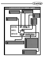
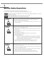
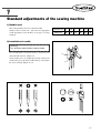
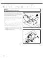
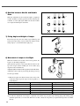
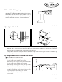
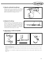
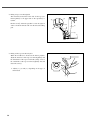
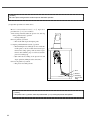
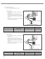
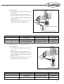
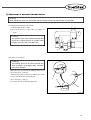
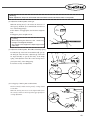
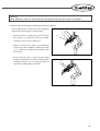
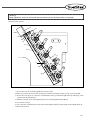
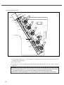
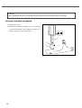
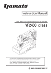
R
User’s
Manual
SF 7400 Series
SF 7500 Series
High-speed Flat Bed
Interlock Sewing
Machine
SUNSTAR MACHINERY CO., LTD.
1) For proper use of the machine,
thoroughly read this manual before use.
2) Keep this manual in a safe place for
future reference in case the machine
breaks down.
MME-051110
lity
a
u
tQ
Besst Pricevice
Be st Ser
Be
1. Thank you for purchasing our product. Based on the rich expertise and
experience accumulated in industrial sewing machine production, SUNSTAR
will manufacture industrial sewing machines, which deliver more diverse
functions, high performance, powerful operation, enhanced durability, and
more sophisticated design to meet a number of user’s needs.
2. Please read this user’s manual thoroughly before using the machine. Make
sure to properly use the machine to enjoy its full performance.
3. The specifications of the machine are subject to change, aimed to enhance
product performance, without prior notice.
4. This product is designed, manufactured, and sold as an industrial sewing
machine. It should not be used for other than industrial purpose.
R
SUNSTAR MACHINERY CO., LTD.
Classification of Pattern Types
Symbol of Series
SUNSTAR
F lat Bed Chain Stitch M/C
Bed Type & No. of Needle
75
Flat Bed-3Needle
74
Flat Bed-2Needle
Main Motor
C
Fortuna Ⅳ
N
Fortuna Ⅲ
M
Clutch Motor
Top Cover Thread
0
Without Top Cover Thread
1
With Top Cover Thread
Needle Distance
32
3.2mm
MODEL
SF 7500 / C
SPEC.
1 56 G
DEVICE
UT-A /
40
4.0mm
48
4.8mm
56
5.6mm
64
6.4mm
/
...
Attachment (Option)
ST-F Top Cover Thread Trimmer(Flat Bed)
CO Covering Guide
HE
Device
Hemming Guide
UT-A Under Thread Trimmer [2-Solenoid Valve Type]
WF Walking Foot
UT-B Under Thread Trimmer [3-Solenoid Valve Type]
ATF Auto Tape Feeder
TL
See Through Light for Hemming
SL
Compact Spot light
TC
Needle Thread Clamp
BN
Binder
G
Shape of Stitch Plate
Standard
L
For long stitch (longer than 2.5mm)
S
For short stitch (shorter than 1.8mm)
CONTENTS
1. Machine Safety Regulations ................................................................6
1) Transporting machine.............................................................................................................6
2) Installing machine ..................................................................................................................6
3) Repairing machine .................................................................................................................6
4) Operating machine .................................................................................................................7
5) Safety devices.........................................................................................................................7
6) Caution mark position............................................................................................................8
7) Contents of marks ..................................................................................................................8
2. Names of machine parts ......................................................................9
3. Specifications .....................................................................................10
4. Installation ..........................................................................................11
1) Installation of table...............................................................................................................11
2) Installation of motor and belt ..............................................................................................13
3) Adjustment of belt tension ..................................................................................................13
4) Attachment of Belt Cover....................................................................................................13
5) Installing cover for needle bar thread guide........................................................................14
6) Installation of thread guide plate .........................................................................................14
5. Sewing speed and rotating direction of pulley .................................14
6. Lubrication ..........................................................................................15
1) Lubricating oil ......................................................................................................................15
2) Supplying oil ........................................................................................................................15
3) Oil Gauge and Oil Window .................................................................................................15
4) Oil change.............................................................................................................................16
5) Cleaning the oil filter ..........................................................................................................16
7. Standard adjustments of the sewing machine .................................17
1) Needle used ..........................................................................................................................17
2) Installation of needle............................................................................................................17
3) Threading..............................................................................................................................18
4
4) Adjustment of thread tension...............................................................................................18
5) Adjustment of presser foot tension......................................................................................19
6) Adjustment of presser foot...................................................................................................19
7) Adjustment of main feed .....................................................................................................19
8) Adjustment of differential feed............................................................................................21
9) Needle Cooling Device and Oil Supply Device for Needle Thread .................................22
8. Adjustment of Sewing Machine .........................................................23
1) Adjustment of Needle Thread Tension ..............................................................................23
2) Adjustment of Top Cover Thread Tension..........................................................................24
3) Adjustment of the Looper Thread Tension .........................................................................24
4) Position of Looper Cam.......................................................................................................25
5) Removing Presser Foot and Amount of Presser Foot Lift .................................................25
6) Relation between Needle and Needle Plate ........................................................................26
7) Fixing Angle and Height of Looper ....................................................................................26
8) Movement of Looper to the Right.......................................................................................26
9) How to Use Timing Gauge ..................................................................................................27
10) Height of Needle Bar .........................................................................................................27
11) Longitudinal Position of Needle and Looper....................................................................27
12) Needle and Needle Guard(Rear) .......................................................................................28
13) Needle and Needle Guard(Front) ......................................................................................29
14) Height of Feed Dogs ..........................................................................................................29
15) Adjustment of needle and spreader ...................................................................................29
9. Automatic Thread Trimmer...............................................................31
1) Operation ..............................................................................................................................31
2) Wiring...................................................................................................................................33
3) Air pressure wiring map .....................................................................................................37
4) Installation of synchronizer sensor......................................................................................40
5) Adjustment of automatic thread trimmer ............................................................................41
6) Adjustment of thread tension release mechanism ..............................................................46
7) Adjustment of air wiper ......................................................................................................49
8) Presser foot lifter mechanism .............................................................................................50
5
1
Machine Safety Regulations
Safety instructions on this manual are defined as Danger, Warning and Caution.
If you do not follow the instructoins, physical injuries and machine damages might be occurred.
Danger : This indication should be observed definitely. If not, there will be a danger during the installation, conveyance and
maintenance of the machine.
Warning : When you follow this indication, injuries from the machine can be prevented.
Caution : When you follow this indication, error on the machine can be prevented.
1) Transporting
machine
Those in charge of transporting the machine should have a full understanding of the machine.
The following indications should be followed when the machine is being transported.
ⓐ More than 2 people must transport the machine.
ⓑ To prevent accidents from occurring during transportation, wipe off the oil on the
machine compeletely.
Danger
2) Installing
machine
Warning
3) Repairing
machine
Caution
6
The machine may not work properly or breakdown, if installed in certain places, Install the
machine where the following qualifications agree.
ⓐ Remove the package and wrappings from the top. Take special notice on the nails on the
wooden boxes.
ⓑ Dust and moisture stains and rusts the machine. Install an airconditioner and clean the
machine regularly.
ⓒ Keep the machine out of the sun.
ⓓ Leave sufficient space of more than 50cm behind, and on the right and left
side of the machine for repairing.
ⓔ EXPLOSION HAZARDS
Do not operate in explosive atmospheres. To avoid explosion, do not operate this
machine in an explosive atomsphere including a place where large quantities of
aerosol spray product are being used or where oxygen is being administered unless
it has been specifically certified for such operation.
ⓕ The machine is not provided with a local lighting due to the feature of machine.
Therefore the illumination of the working area must be fulfilled by end user.
When the machine needs to be repaired, only the assigned troubleshooting engineer educated
at the company should take charge.
ⓐ Before cleaning or repairing the machine, turn off the main power and wait 4 minutes till
the machine is completely out of power.
ⓑ Not any of the machine specifications or parts should be changed without consulting the
company. Such changes may make the operation dangerous.
ⓒ Spare parts produced by the company should only be used for replacements.
ⓓ Put all the safety covers back on the machine after the machine has been repaired.
4) Operating
machine
Warning
SF 7500 Series is made to sew patterns on fabrics and other similar materials for industrial use.
Follow the following indications when operating the machine.
ⓐ Read through this manual carefully and completely before operating the machine.
ⓑ Wear proper clothes for work.
ⓒ When the machine is in operation, do not bring your hands or body near the moving parts
of the machine, such as needle, looper, spreader, thread take-up lever and pulley, etc.
ⓓ Keep the covers and safety plates on the machine during operation.
ⓔ Be sure to connect the earthing conductor.
ⓕ Turn off the main power and check if the switch is turned“off”before opening electric
boxes such as the control box.
ⓖ Stop the machine before threading the needle or checking after work.
ⓗ Do not step on the pedal when turning the power on.
ⓘ Do not operate the machine with any cooling fan blocked.
The air-filter on control box must be cleaned once a week.
ⓙ If possible, install the machine away from source of strong electrical noise such as high
frequency welding machines
[ Warning ]
Keep cover in place before operating, turn off power before inspecting or adjusting in order
to prevent physical injury from belt.
5) Safety devices
ⓐ Safety label : Cautions during machine operation
ⓑ, ⓒ Thread take-up lever cover : A device designed to prevent any physical contact with
thread take-up lever
ⓓ Belt cover: A device designed to prevent the body and clothes from getting jammed by
the moto
ⓔ Finger guard : A device to prevent contact between fingers and needles
ⓕ Safety plate: Eye-protecting device
Caution
ⓑ
ⓒ
ⓓ
ⓔ
ⓕ
ⓐ
7
6) Caution mark
position
Caution mark is attached on the machine for safety.
When you operate the machine, follow the directions on the mark.
CAUTION
주 의
Do not operate without finger guard and
safety devices. Before threading, changing
and needle, cleaning etc. switch off
main switch.
손가락 보호대와 안전장치 없이 작동하지
마십시오.
실, 바늘교환시나 청소전에는 반드시 주전원의
스위치를 꺼 주십시오.
CAUTION
경 고
[ Figure 1 ]
7) Contents of
marks
Caution
(1)
CAUTION
주 의
Do not operate without finger guard
and safety devices. Before threading,
changing and needle, cleaning
etc. switch off main switch.
손가락 보호대와 안전장치 없이 작동하지 마
십시오.
실, 바늘교환시나 청소전에는 반드시
주전원의 스위치를 꺼 주십시오.
(2)
CAUTION
경 고
8
2
Names of machine parts
⑭
⑥
⑦
⑮
⒔
⑤
④
③
⒃
⑫
⑧
①
②
⑨
⑪
⑬
⑩
⒕
[ Figure 2 ]
①
②
③
④
⑤
⑥
⑦
Arm
Bed
Face plate
Upper cap
Oil window
Knee-lifting cylinder
Upper shaft pulley
Safety devices
⑮ Thread guide cover for needle thread
⒃ Thread take-up lever cover for needle thread
⑧
⑨
⑩
⑪
⑫
⑬
⑭
Thread-adjusting device
Oil gauge
Presser foot
Main feed regulating button
Air wiper
Power switch
Bobbin stand
⒔ Finger guard
⒕ Safety plate
9
3
Specifications
Model
SF 7500 Series
Description
High-speed Flat Bed Three-Needle Interlock Sewing Machine
Stitch Type
ISO 406,407,602,605
For use
Sewing speed
General seaming of knitted materials
Max. 6000 s.p.m (In the case of on-and-off operation)
1.4~3.6mm
Stitch length
Stitches per inch: 7~18; The number of stitches per 30mm: 8~21
Needle
UY×128GAS No. 65 ~ No. 90(Standard : No. 70)
2-needle: 3.2, 4.0, 4.8, 5.6, 6 mm
Needle clearance
3-needle: 5.6, 6.4 mm
Needle bar stroke
Lifting of presser foot
Feed Regulation
31mm
Max. 8.0 mm (7 mm if equipped with a spreader)
Push-Button type
Max. Normal Differential Ratio → 1 : 2
Differential ratio
Max. Reverse Differential Ratio → 1: 0.7
Differential Feed Regulation
Lubrication
Oil used
Oil fan capacity
10
Adjusting screw and adjusting lever
Automatic lubrication by oil pump
All-purpose machine oil
1100CC
4
Installation
1) Installation of table
⑴ Types of table
A. Supporting Board Type
[ Figure 3 ]
11
(2) Installation of Supporting Board
Install the sewing machine as shown in [Fig. 4].
Insert screws into the bed supporting board to fix the bed on the table. Place rubber cushions on top of screws for safety.
Then install the sewing machine.
[ Figure 4 ]
※ Required Number of Spacer A
SF 7500 Series
Thickness of Table
40mm
45mm
50mm
12
Number of A
3×4 = 12
2×4 = 8
1×4 = 4
2) Installation of motor and belt
Use a 3-Phase, 2-Pole, 550W(3/4 HP) clutch motor and M-type V-belt for the machine.
Start the pedal. When the motor pulley begins to move to the left, adjust the position of the motor so that the centers of the
motor pulley and the M/C pulley meet with each other.
s.p.m of machine
Diameter. of Motor
Pulley(mm)
50Hz
60Hz
75
3,200
3,900
80
3,400
4,100
85
3,600
4,400
90
3,900
4,700
100
4,300
5,200
110
4,700
5,700
120
5,100
6,200
130
5,500
6,700
61mm
40。
5.5mm
10mm
[ Figure 5 ]
※ The diameter of pulleys in the market is generally set with a 5 mm clearance.
3) Adjustment of belt tension
[ Warning ]
Be sure to turn the power switch off before adjusting belt
tension.
②
①
10~20mm
Turn the screw④ of the motor③ around. Adjust the belt ①
to go in approximately 10~20mm when its center portion is
pushed with a finger. (Refer to figure 6)
④
③
[ Figure 6 ]
4) Attachment of Belt Cover
[ Warning ]
Always install the belt cover for safety.
Fasten the belt cover (upper)① with a screw② as shown in
figure 7.
①
②
[ Figure 7 ]
13
5) Installing cover for needle bar thread
guide
①
As illustrated in the figure, fix the cover② for needle bar
thread guide onto the arm with two screws①.
②
[ Figure 8 ]
6) Installation of thread guide plate
Use screws ① (2 each) to mount the thread guide plate ②
onto the arm as described below in the figure.
②
②
①
[ Figure 9 ]
5
Sewing speed and rotating direction of pulley
The maximum speed of the sewing machine is 6,000 s.p.m,
and 4,000 s.p.m for commercial use.
To ensure durability, run the sewing machine at 4,000 s.p.m
for 200 hours of operation (or 1 month) when using the
machine for the first time.
As shown in figure 10, the rotating direction of the lower
shaft pulley① and upper shaft pulley② is clockwise.
②
①
[ Figure 10 ]
14
6
Lubrication
[ Warning ]
Be sure to turn the power switch off before oiling
1) Lubricating oil
Use industrial-purpose lubricating oil supplied by SunStar or SF oil by YANASE for this particular type of sewing machine.
[ Caution ]
Do not put foreign materials into the lubricating oil. It will degrade the lubricating oil and cause mechanical breakdowns.
2) Supplying oil
The sewing machine is not oiled when shipped out from the factory. To ensure trouble-free use of the sewing machine, open
the upper rubber lid ① and supply oil to the upper line of the oil gauge ③.
①
②
③
[ Figure 11 ]
[ Figure 12 ]
[ Caution ]
Too little oil may cause mechanical breakdowns and too much may degrade the quality of sewing materials. Be sure to
adjust the amount of oil appropriately.
3) Oil Gauge and Oil Window
Always check the oil gauge ③ before starting the machine. Supply oil if the remaining oil comes short of the lower line of
the gauge.
When operating the machine, check the flow of the oil through oil window ②.
15
4) Oil change
To ensure durability of the sewing machine, be sure to
change oil after 250 hours of initial operation.
① Separate the V belt from the motor pulley, and then
separate the sewing machine from the table.
② Loosen [the oil release screw①] to release the lubricant
inside.
Make sure that the V belt is not smeared by oil.
③ Release the lubricant and tightly fasten [the oil release
screw①].
④ See "2)
「Supplying oil」”to supply new oil.
①
[ Figure 13 ]
5) Cleaning the oil filter
Oil will not supply smoothly if dust gets built up in oil filter
②. Check the oil filter once every six months.
Check the oil filter through the oil window if there is no or
only little amount of oil being supplied.
Before checking the oil filter, remove the oil filter cover ③.
Clean dust build-ups inside the oil filter.
②
③
O-ring
[ Figure 14 ]
[ Caution ]
When removing the oil filter cover, be sure to prevent the remaining oil in the oil filter from leaking.
16
7
Standard adjustments of the sewing machine
1) Needle used
This sewing machine uses UY×128GAS needles.
Needles come in various size. Select the most appropriate
needle depending on the thickness or the type of sewing
materials.
Japanese size
9
10
11
12
13
14
Metric size
65
70
75
80
85
90
2) Installation of needle
[ Warning ]
Turn the power switch off before installing a needle.
Use a needle driver to loosen the screw ①, and remove the
old needle with tweezers. (Figure 15)
Set the needle groove to completely face back, and raise the
needle to the groove tip of the needle holder ②. Then fasten
the screw ① firmly. (Figure 16, 17)
②
①
[ Figure 15 ]
[ Figure 16 ]
[ Figure 17 ]
17
3) Threading
Insert the thread as shown in figure 18 for 3-needle sewing machine.
If treading is not done correctly, stitches may skip, threads may break or tension may be uneven. A, B and C stand for each
needle thread, D for top cover thread and E for looper thread.
Except for the second needle thread in the case of 2-needle sewing machine, refer to the above instructions for threading.
A B C
E
D
When using wool thread
⑤
Do not insert thread when using wool thread
[ Figure 18 ]
4) Adjustment of thread tension
Thread tension must be adjusted according to the type of
threads and fabrics, stitch length and other sewing
conditions.
Thread tension can be adjusted by rotating the thread
adjusting device cap①. Turn clockwise to strengthen and
counterclockwise to weaken the tension.
①
Strong
Weak
[ Figure 19 ]
18
5) Adjustment of presser foot tension
If the sewing material is in good condition, it is better to
have as little tension as possible on the presser foot.
Loosen the presser bar nut① and turn the presser bar screw
② with a coin to adjust the tension of the presser bar. Retighten it afterwards.
Tension will become stronger if the screw② is turned
clockwise, and weaker if turned counterclockwise.
②
Weak
Strong
①
[ Figure 20 ]
6) Adjustment of presser foot
[ Warning ]
Be sure to turn the power switch off before adjusting the
position of the presser foot.
①
After unfastening the screw ①, move the front part of the
presser foot left and right to bring the needle to pass the
center of the needle passage of the presser foot.
Needle
[ Figure 21 ]
7) Adjustment of main feed
[ Warning ]
Be sure to turn the power switch off before adjusting stitch length.
⑴ Stitch length
Stitch length can be adjusted straight from 1.4mm to 3.6 mm
The table below shows stitch length, number of stitches per inch(25.4mm) and per 30 mm.
Stitch length (mm)
No. of stitches (per inch)
No. of stitches (per 30mm)
3.6
7
8
2.4
10.5
12.5
1.4
18
21
19
⑵ Change of stitch length
①
②
③
[ Figure 22 ]
[ Figure 23 ]
Press lightly stitch length-adjusting button① with your left hand so that the end comes in contact with inner parts.
With the button① pushed in, turn the upper shaft pulley② with your right hand so that the button① goes in deeper.
While [the button①] is pressed hard, turn the upper-shaft pulley to change the stitch length. Turn [the upper-shaft pulley
②] clockwise. The closer graduation
「L」becomes to [Mark③], the larger the stitch length becomes.
When the mark points at「L」, the stitch length becomes 3.6mm. When [the upper-shaft pulley②] is turned counterclockwise, and graduation「S」gets closer to [Mark③], the stitch length gets smaller. When the mark points at「S」, the
stitch length becomes 1.4mm. Although graduations are same, the corresponding stitch lengths could be different
depending on types of fabrics, fabric thickness and size of differential. Therefore, the upper-shaft pulley needs to be
readjusted depending on situations.
[ Caution ]
When using sewing machines mounted with pneumatic trimming devices designed to automatically find the needle
location, e.g., UT-A, UT-B or ST-C, be sure to turn off the power before stitch width conversion.
※ Main Feed Adjusting Button Stopper
Use this function to keep the set stitch length same.
Loosen [the screw③] to use the stopper. Turn [the
main feed adjusting button stopper②] upward to set
it up below [the main feed adjusting button①] and
fasten [the screw③].
②
①
[ Figure 24 ]
20
8) Adjustment of differential feed
[ Warning ]
Be sure to turn the power switch off before adjusting differential feed.
(1) Normal Differential Feed (Shrink Sewing)
Loosen [the differential lever adjusting nut①]. Move
[the differential feed lever②] up or down to place it at
the desired position, and fasten [the nut①].
When the lever is set at [Graduation (Long) (C)], the
ratio of main feed to differential feed becomes 1:1.
When [the lever②] is set at the position higher than
Graduation C, the lever is in the normal differential feed
mode. The graduations located above Graduation C refer
to 1:1.25, 1:1.15, 1:1.75 and 1:2 from the bottom.
①
②
③
[ Figure 25 ]
(2) Reverse Differential Feed (Stretch Sewing)
When [the differential feed lever②] is set at the place
below [Graduation (Long)③], it is in the reverse
differential feed mode. When the lever is set at
[Graduation S], the ratio of main feed to differential feed
becomes 1:0.7.
④
③
④
[ Figure 26 ]
(3) Adjustment of Differential Feed During Operation
When differential ratio needs to be adjusted during sewing, connect the lever to the chain.
To adjust the maximum or minimum limits of the differential feed lever, use [the differential feed lever stoppers (2EA)④].
※ Depending on the stitch length, the scope of differential ratios is different. Please see the table below
Stitch Length (mm)
Max. Normal Differential Ratio
Max. Reverse Differential Ratio
3.6
1 : 1.1
1 : 0.7
2.5
1 : 1.6
1 : 0.7
2.0
1 : 1.8
1 : 0.7
1.4
1:2
1 : 0.7
21
9) Needle Cooling Device and Oil Supply Device for Needle Thread
[ Warning ]
Be sure to turn the power switch off before work.
High-speed sewing generates heat as a result of frictions
between the needle and sewing materials. Heat may result
in thread breaks, skipped stitches, or enlarged stitch holes
when used with polyester threads or fabrics.
To prevent such troubles, this sewing machine comes
attached with the needle cooling device and needle thread
lubricating device as a standard option.
The silicon-type oil is the most efficient.
①
Note :
Open [the silicon oil supply tank cap①] of the needle
cooling device and [the needle thread oil supply tank cover
②] of [the needle thread oil supply device] to check the oil
volume. When oil is insufficient, supply more oil.
※ If there is no need for silicon due to specific sewing
conditions, remove the felt to prevent the needle and the
thread from passing the dry felt.
[ Figure 27 ]
②
[ Figure 28 ]
22
8
Adjustment of Sewing Machine
1) Adjustment of Needle Thread Tension
When the tip of [the needle thread take-up①] is 52mm
away from the center of [the screw②], and the needle bar is
at the highest position, [Part a] of [the needle thread take-up
①] becomes horizontal.
This is a standard needle thread tension.
If you desire to raise the needle thread tension, move [the
needle thread take-up①] in the Y direction. If you desire to
lower the needle thread tension, move the take-up in the X
direction.
To make this adjustment, loosen [the screw②].
52mm
Y
a
X
①
②
[ Figure 29 ]
If more adjustment is needed, loosen [the screw③] and
check the thread tension, while moving the position of [the
thread eyelet④]
When the thread eyelet is moved in the Y direction, the
tread tension will increase. When it is moved in the X
direction, the thread tension will decrease.
The standard setting is to set the distance between the
middle of [the screw③] and the upper tip of [the thread
eyelet④] at 8mm.
③
④
3mm
Y
X
[ Figure 30 ]
For some types of threads, looping is not an easy thing to
do. Wrong loops may make it difficult for the looper to pass
needle thread loop and cause skipped stitches.
In such case, pull the needle thread through the auxiliary
tension-adjusting device of the needle thread ① as shown in
figure 31.
①
[ Figure 31 ]
23
Use the needle thread guide ③ when using stretchable
threads such as synthetic thread and the loop of needle
thread is unstable.
It is a standard setting to bring the center of the needle hole
of the needle bar take up ② against the upper side of the
needle thread guide when the needle bar is at its lowest
position.
The height of the needle bar guide can be adjusted by
loosening the screw ④.
(refer to figure 32)
③
②
④
[ Figure 32 ]
2) Adjustment of Top Cover Thread Tension
X
When [the top cover thread eyelet(Right)①] is moved up in
the X direction, the take-up volume decreases. When it is
moved down in the opposite way, the take-up volume
increases.
When an elastic thread such as woolly thread is used as the
top cover thread, loosen [the screw②] to move down [the
top cover thread eyelet (Right)①] in the Y direction. This
time make sure that the top cover thread passes through the
bottom hole as in the right figure.
②
Y
①
for woolly thread
[ Figure 33 ]
3) Adjustment of the Looper Thread Tension
The figure shows the looper thread take-up.
The standard setting is to place the thread holes of [the
looper thread guide⑥,⑦] at [Mark X] on [the looper thread
cast-off plate⑤].
To increase the length of loose thread, loosen the fixing
screws for [the looper thread guides⑥,⑦], and move them
forward and then fix them. To reduce the length of loose
thread, move the looper thread guides backward and fix
them.
⑤
⑥
less
X
much
less
much
⑦
[ Figure 34 ]
Note :
If the looper thread’s loose thread is too long, it might cause
stitch skips. Make sure that the looper thread’s loose thread
is not too long.
When using woolly thread, move [the looper thread guides
⑥,⑦] forward to the maximum and make sure that the
thread doesn’t pass through [the supplementary tension disc
(H)].
for woolly thread
⑥
⑦
[ Figure 35 ]
24
4) Position of Looper Cam
In the figure, the looper cam is viewed from the side of the needle bar.
When the left needle reaches the middle of the looper, lower the needle from the highest position so that the thread stays
away from the highest position of [the looper cam①].
See the figure below.
Make adjustments by loosening [the screw②].
thread
②
1/2
①
[ Figure 36 ]
[ Figure 37 ]
5) Removing Presser Foot and Amount of Presser Foot Lift
Loosen [the screw④] for [the presser plate collar③]. Press [the lap lift lever①] and separate the presser foot. When [the lap
lift lever①] is pressed, adjust the maximum height of the presser foot to set the distance between the front face of the needle
plate and the bottom of the presser foot at 7.0mm (when the spreader is equipped).
When this adjustment is completed, set the distance between the bottom of [the presser bar bushing⑥] and the front face of
[the presser bar collar③] at 0.2mm and fasten [the screw④].
If there is no [the spreader⑦], set the distance at 8.0mm. In this case, [the presser bar collar③] is not used.
⑥
②
0.2mm
①
③
④
⑦
7.0mm
(8.0mm)
stitch plate
[ Figure 38 ]
[ Figure 39 ]
25
6) Relation between Needle and Needle
Plate
When the adjustment of the needle bar height is completed,
needles should be accurately positioned in line following the
solid line as in the right figure. Make sure that the needles
are not placed following the dotted line.
[ Figure 40 ]
7) Fixing Angle and Height of Looper
Insert the looper into the end of [the looper holder①] and
fasten [the looper fixing screw②]. Then the height and the
fixing angle (3°) are determined (See [Fig. 41])
①
②
[ Figure 41 ]
8) Movement of Looper to the Right
When the needle bar is located at the lowest position, the
looper is on the furthest right side.
[The right-side position of the looper (distance between the
tip of the looper and the middle part of the needle) (D)]
depends on the needle distance.
Adjust [the right feed volume of the looper] based on the table below.
Adjustment can be made by loosening [the fixing screw①]
for the looper holder.
※ Without exception, the distance between the center of the
needle bar and the tip of the looper is 6mm regardless of
needle distance.
Gauge between Needles
3.2mm
4.0mm
4.8mm
5.6mm
6.4mm
Gauge mark
A
B
C
D
E
①
[ Figure 42 ]
Right Feed Volume of Looper
4.4 mm
4.0 mm
3.6 mm
3.2 mm
2.8 mm
☆ To make the adjustment of the looper’s right-side feed volume easy, use [the looper timing gauge]. The timing gauge
should be purchased as an extra item. When it is needed, contact the shop where you purchased the product or SunStar
directly.
26
9) How to Use Timing Gauge
The timing gauge is marked with A, B, C, D, and E
depending on needle distance. When the looper is located on
the furthest right side and the right needle is nested at
corresponding needle distance“V groove”, align the looper
with the timing gauge and fasten“the looper holder screw.”
[ Figure 43 ]
10) Height of Needle Bar
0.5~1.0mm
①
[ Figure 44 ]
[ Figure 45 ]
When the end tip of the looper passes the left needle center, it must pass the needle groove at 0.5~1.0 mm off from the
upper part. In other words, the height of the needle is set by the looper.
Using a driver, unfasten the screw① of the needle bar holder through a hole in the face plate and adjust the needle bar up
and down to get the right needle height.
11) Longitudinal Position of Needle and Looper
☆ In case where three needles are used
When [the tip of the looper(A)] meets [the left needle
①], the needle distance should be 0.2~0.3mm.
When [the tip of the looper(A)] meets [the central needle
②], the needle distance should be 0.05~0.15mm.
When [the tip of the looper(A)] meets [the right needle
③], needles should be slightly contacted (some 0.2mm).
In this case, press [the needle guide(Rear)] for [the right
needle③], and adjust the distance between [the tip of the
looper(A)] and [the right needle③] at 0~0.05mm.
Make the adjustment by loosening the screw for [the
looper holder].
A
0.2~
0.3mm
①
②
③
[ Figure 46 ]
27
☆ In case where two needles are used
When [the tip of the looper(A)] meets [the left needle
④], the needle distance should be 0.2~0.3mm.
When [the tip of the looper(A)] meets [the right needle⑤],
the needles should be slightly contacted (some 0.2mm).
In this case, press [the needle guide(Rear)] for [the right
needle⑤], and adjust the distance between [the tip of the
looper(A)] and [the right needle⑤] at 0~0.05mm.
Make the adjustment by loosening the screw for the
looper holder.
A
0.2~
0.3mm
④
⑤
[ Figure 47 ]
12) Needle and Needle Guard(Rear)
☆ Height of Needle Guard(Rear)
When needle guard (R) is at the lowest point of the
needle bar, align the center of the needles along the line a
of the needle guard (R) .
A
a
[ Figure 48 ]
☆ Longitudinal position of needle guard(R)
When the end tip of the looper comes to the center of the right needle, press the needle guard (R) to adjust the clearance
between the needle and the looper at 0~0.05 mm. At this point, be sure to set the distance between the left needle and the
needle guard (R) at 0~0.05 mm. Adjustments can be done by loosening the screws (①, ②).
0~0.05mm
②
0~0.05mm
①
[ Figure 49 ]
28
[ Figure 50 ]
13) Needle and Needle Guard(Front)
When the tip of the looper is located at the center of the left
and right needles, adjust the distance between each needle
and [the needle guard(Front)ⓝ] at 0~0.3mm respectively.
Make the adjustment by loosening [the screw①].
ⓝ
①
0~0.3mm
[ Figure 51 ]
14) Height of Feed Dogs
B
When the feed dog is located at the highest position, the
front face of the feed dog and the front face of the needle
plate are in parallel. In this case, make [the differential feed
dog(A)] and [the main feed dog(B)] have the same height,
and set the height between the front face of the needle plate
and the front face of the feed dog at 1.0~1.2mm.
A
1.0~1.2mm
[ Figure 52 ]
15) Adjustment of needle and spreader
⑴ Fixing of spreader
0.5~0.8mm
a
③
①
①
4.5~5.5mm
②
8.5~9.5mm
[ Figure 53 ]
[ Figure 54 ]
[ Figure 55 ]
When the spreader① moves to the left, the clearance between the left needle and the hook tip of the spreader (a) is
0.5mm ~ 0.8mm. (Figure 53)
When the spreader sits at the far left, the distance from the left needle center to the hook tip of the spreader (a) is 4.5mm ~
5.5mm.
The spreader can be adjusted by untightening the spreader fixing screw② and the spreader handle fixing screw③.
(Figure 55)
29
⑵ Fixing of top cover thread guide
The clearance between the lower side of the top cover
thread guide④ to the upper side of the spreader① is
0.5mm.
Fix the screw⑤ when the spreader is at its far right, in
order to hook the thread well onto the thread hooking
part.
⑥
④
1.0mm
⑤
④
0.5mm
①
⑥
①
[ Figure 56 ]
⑶ Fixing of the top cover thread eyelet
When the needle bar is located at the lowest position,
adjust the front face of the top cover thread guide④ and
the thread hole of the top cover thread eyelet⑥ to be at
the central line of the top cover thread guide④ slot and
fasten the screw⑦.
④
※ Adjust (1), (2) and (3), depending on the type of
thread used.
⑥
⑦
[ Figure 57 ]
30
9
Automatic Thread Trimmer
1) Operation
[ Caution ]
Be sure to lay sewing materials under the presser foot before operation.
(1) Operation procedures for UT-B and UT-A device.
Motor is selected either from ① or ②. Operation
procedures for ① or ② are as follows.
A. Put sewing materials under the presser foot and step
on the pedal towards ① position.
B. Leave pedal at ② neutral
→ The needle will stop at the highest point.
C. Step the pedal backward towards ③ position.
→ The trimming device will begin to move under the
needle plate to cut the needle thread and looper
thread. The looper thread will be caught by clamp
spring, and air wiper will run for two seconds, and
then presser foot will go up.
→ (For UT-A device, lifting of the presser foot and
wiper operation will begin at the same time.)
D. Leave the pedal at ② neutral
→ The presser foot will go down.
① Start
② Neutral
③ Trimming,
Presser foot
lifting
[ Figure 58 ]
[ Caution ]
If the pedal is not in ① position, move the pedal towards ② or ③ to bring the presser foot up/down.
31
[ Caution ]
Be sure to place sewing materials under the presser foot before operation.
(2) Operation procedures for ST-C device.
Motor is selected either from ① or ②. Operation
procedures for ① or ② are as follows.
A. Put sewing materials under the presser foot and step
on the pedal towards ① position
→ Sewing will begin.
B. Leave pedal at ② neutral
→ The needle will stop at the highest point.
C. Step the pedal backward towards ③ position.
→ The trimming device will begin to move under the
needle plate to cut the needle thread and looper
thread. The clamp spring will catch the looper
thread, after trimming top cover thread, and the
presser foot will go up.
→ (For UT-A device, lifting of the presser foot and
wiper operation will begin at the same time.)
D. Leave the pedal at ② neutral.
→ The presser foot will go down.
① Start
② Neutral
③ Trimming,
Presser foot
lifting
[ Figure 59 ]
[ Caution ]
If the pedal is not in ① position, move the pedal towards ② or ③ to bring the presser foot up/down.
32
2) Wiring
(1) Limit switch
A. Adjusting limit switch
a. Loosen screws ① and ②.
b. When trimming blade returns to its original
position, adjust so that the switch is turned on.
c. Fix screws ① and ②.
①
②
[ Figure 60 ]
B. Connecting limit switch
a. General Servo motor A (Fortuna Ⅲ)
Link the limit switch cord to the 12P-connector as
follows.
White
Black
Black
White
Switch and lamp connector
[ Figure 61 ]
b. Small motor A (Fortuna Ⅳ)
Link the limit switch cord to 8P-connector as
follows.
White
Black
Switch and lamp connector
Black
White
[ Figure 62 ]
33
(2) Connecting solenoid valve
A. General Servo Motor(Fortuna Ⅲ servo motor)
a. For UT-B device
·Press solenoid valve buttons to check how each
device moves.
·If the device does not work, check the cords.
·For the pneumatic solenoid valve carries polarity,
check the connection between the cable and the
connector.
·The device will not work if the cords are plugged
in incorrectly to opposite power.
Standard solenoid connector
Knee-lifting solenoid connector (Green)
[ Figure 63 ]
Solenoid valve number
Solenoid valve application
Connector type
Pin number
1
Presser foot lifting
Knee-lifting solenoid connector
3 [+], 4 [signal]
2
Lower trimming
Standard solenoid connector
2 [signal], 6 [+]
3
Air wiper operation
Standard solenoid connector
3 [signal], 7 [+]
b. For UT-A device.
·Press solenoid valve buttons to check how each
device moves.
·If the device does not work, check the cords.
·For the pneumatic solenoid valve carries polarity,
check the connection between the cable and the
connector.
·The device will not work if the cords are plugged
in incorrectly to opposite power.
Standard solenoid connector
Knee-lifting solenoid connector (Green)
[ Figure 64 ]
34
Solenoid valve number
Solenoid valve application
Connector type
Pin number
1
Presser foot lifting
Knee-lifting solenoid connector
3 [+], 4 [signal]
2
Lower trimming
Standard solenoid connector
2 [signal], 6 [+]
c. For ST-C device.
·Press solenoid valve buttons to check how each
device moves.
·If the device does not work, check the cords.
·For the pneumatic solenoid valve carries
polarity, check the connection between the cable
and the connector.
·The device will not work if the cords are
plugged in incorrectly to opposite power.
Standard solenoid connector
Knee-lifting solenoid connector (Green)
[ Figure 65 ]
Solenoid valve number
Solenoid valve application
Connector type
Pin number
1
Presser foot lifting
Knee-lifting solenoid connector
3 [+], 4 [signal]
2
Lower trimming
Standard solenoid connector
2 [signal], 6 [+]
3
Top cover thread trimming
Standard solenoid connector
3 [signal], 7 [+]
B. Small Motor(Fortuna Ⅳ Compact Servo Motor)
a. For UT-B device.
·Press solenoid valve buttons to check how each
device moves.
·If the device does not work, check the cords.
·For the pneumatic solenoid valve carries
polarity, check the connection between the cable
and the connector.
·The device will not work if the cords are
plugged in incorrectly to opposite power.
Standard solenoid connector
[ Figure 66 ]
Solenoid valve number
Solenoid valve application
Connector type
Pin number
1
Presser foot lifting
Standard solenoid connector
2 [+], 10 [signal]
2
Lower trimming
Standard solenoid connector
11 [signal], 3 [+]
3
Air wiper operation
Standard solenoid connector
12 [signal], 4 [+]
35
b. For UT-A device.
·Press solenoid valve buttons to check how each
device moves.
·If the device does not work, check the cords.
·For the pneumatic solenoid valve carries polarity,
check the connection between the cable and the
connector.
·The device will not work if the cords are plugged
in incorrectly to opposite power.
Standard solenoid connector
[ Figure 67 ]
Solenoid valve number
Solenoid valve application
Connector type
Pin number
1
Presser foot lifting
Standard solenoid connector
2 [+], 10 [signal]
2
Lower trimming
Standard solenoid connector
11 [signal], 3 [+]
c. For ST-C device.
·Press solenoid valve buttons to check how each
device moves.
·If the device does not work, check the cords.
·For the pneumatic solenoid valve carries
polarity, check the connection between the cable
and the connector.
·The device will not work if the cords are
plugged in incorrectly to opposite power.
Standard solenoid connector
[ Figure 68 ]
36
Solenoid valve number
Solenoid valve application
Connector type
Pin number
1
Presser foot lifting
Standard solenoid connector
2 [+], 10 [signal]
2
Lower trimming
Standard solenoid connector
11 [signal], 3 [+]
3
Top cover thread trimming
Standard solenoid connector
12 [signal], 4 [+]
3) Air pressure wiring map
(1) UT-B device
2.5×4×350mm
2.5×4×150mm
IN
2.5×4×300mm
OUT
2.5×4×400mm
2.5×4×300mm
solenoid valve
air pressure : 0.4MPa~0.5MPa
(4Kgf/cm2~5Kgf/cm2)
4×6×1,500mm
[ Figure 69 ]
37
(2) UT-A device
2.5×4×150mm
2.5×4×150mm
IN
OUT
2.5×4×300mm
2.5×4×200mm
2.5×4×200mm
2.5×4×300mm
solenoid valve
air pressure : 0.4MPa~0.5MPa
(4Kgf/cm2~5Kgf/cm2)
4×6×1,500mm
[ Figure 70 ]
38
(3) ST-C device
2.5×4×350mm
2.5×4×300mm
2.5×4×580mm
2.5×4×600mm
2.5×4×300mm
solenoid valve
air pressure : 0.4MPa~0.5MPa
(4Kgf/cm2~5Kgf/cm2)
4×6×1,500mm
[ Figure 69 ]
39
4) Installation of synchronizer sensor
[ Warning ]
Leave the trimming cylinder plug pulled off from the control box in the motor. Otherwise, parts can be damaged.
③
(1) Install the synchronizer ① on the machine and fasten
screw ② lightly.
(2) Turn on the motor switch.
(3) Press the pedal and form a few stitches.
(4) Press the pedal backward to stop the needle.
(5) Loosen the screw ② and turn the line ④ on the upper
shaft pulley to align with the hole ⑤ in the arm. Be sure
to keep the position of the screw ② unchanged.
①
②
[ Figure 72 ]
(6) To see whether the needle bar is located at 0.5mm below
the highest point, press the pedal and run the machine.
⑤
④
[ Figure 73 ]
[ Caution ]
(1) At this point, the needle bar should be positioned at the highest point.
(2) The optimal condition for the synchronizer sensor is when the needle bar is 0.5mm below the highest point by
turning the upper shaft pulley a bit more.
40
5) Adjustment of automatic thread trimmer
[ Warning ]
Before adjustments, always turn off the motor switch and check to make sure that the motor is in stop mode.
(1) Adjusting thread trimming air cylinder
A. The desirable stroke is 15mm.
B. Loosen the screw ② of the collar ① to adjust the
stroke.
[ Caution ]
The operation status of the automatic thread trimmer
should be re-adjusted when air cylinder stroke
changes. Check the status of the limit switch.
①
②
15mm
[ Figure 74 ]
(2) Position of moving mes
[ Warning ]
The trimming device can be moved manually only
when the needle is at the highest point. Otherwise,
parts can be damaged.
When the looper is located on the furthest left side, move
the moving mes③ to the left.
Adjust the tip of the moving mes to make it pass 14mm
away⑤ from the looper on the right side.
(above the looper’s ridge⑥)
Loosen the screw④ to make the adjustment.
14mm
①
④
⑤
⑥
③
[ Figure 75 ]
41
[ Warning ]
Before adjustments, always turn off the motor switch and check to make sure that the motor is in stop mode.
(3) Adjustment of Moving Mes and Needle
a. Loosen the nuts④,⑤.
b. Move the moving mes to the left in full.
c. Use the trimming connecting rod⑥ to adjust the
distance between the hook for the needle thread and
the left needle at 2.5~ 3.0mm.
· To widen the distance, turn the trimming connecting
rod in the“W”direction.
· To narrow down the distance, turn the trimming
connecting rod in the“N”direction.
2.5~3.0mm
d. Tightly fasten the nuts④,⑤.
[ Figure 76 ]
Tightly fasten the nuts④, ⑤, and confirm whether the
trimming device connecting rod② and the moving mes
body③ are operating smoothly.
②
③
[ Figure 77 ]
W
④
N
⑥
⑤
[ Figure 78 ]
42
[ Warning ]
Before adjustments, always turn off the motor switch and check to make sure that the motor is in stop mode.
(4) Adjustment of Moving Mes and Looper
When the moving mes① is in motion, the front face of
the looper② should be 0.1~0.3mm distant from the rear
face of the clamp spring③.
If the distance is inappropriate, the fixed mes might be
bent.
If it happens, please straighten it out. .
[ Caution ]
When adjusting the distance, don’t make any
changes in the height of the looper.
Any change in the height of the looper might cause
stitch skips.
0.1~
0.3mm
①
②
③
[ Figure 79 ]
(5) Adjustment of Moving Mes, Fixed Mes and Clamp Spring
To make the tip of the hook for needle thread④ pass by
the rim⑤(I) of the fixed mes, adjust the tip of the hook
for looper thread⑥ to pass by the rim⑦ of the clamp
spring. And adjust the inner side of the moving mes to
pass by the rim⑦ of the clamp spring.
Loosen the screw⑨ for adjustment.
⑦ ⑤
④ ⑧
⑥
⑨
⑤
④
⑦
⑥
Ⅰ
Ⅱ
[ Figure 80 ]
(6) Overlapping of Moving Mes and Fixed Mes
The fixed mes⑪ and the moving mes⑩ overlap around
0.2~0.5mm.
When the moving mes moves to the right in full, loosen
the screw⑬ and move the hexagonal stopper plate⑫ for
overlap adjustment.
⑫
⑬
0.2~0.5mm
⑩
⑪
[ Figure 81 ]
43
[ Warning ]
Before adjustments, always turn off the motor switch and check to make sure that the motor is in stop mode.
(7) Adjustment of Remaining Thread After Sewing Is Finished
When the trimming device is in motion, the moving mes
① moves to the left and the fixed mes body④ moves to
the furthest left of the moving mes return spring.
When the distance between the tip of the clamp spring②
and the feed dog on the right side is 0~0.5mm, fasten the
screw⑦ to attach the fixed mes stopper(L)⑤ to a part of
the fixed mes body⑥.
The moving mes① returns from the furthest left along
with the needle thread and the looper thread.
Then it is overlapped with the fixed mes③. The meses
cut the needle thread and the looper thread.
Until the threads are cut off completely, the clamp spring
② should be 0~0.5mm away from the feed dog. This
position determines the length of the remaining thread
after sewing is finished.
⑥
②
⑤
⑦
0~0.5mm
④
①
③
[ Figure 82 ]
⑨
⑪
· To make the remaining thread shorter, locate the
clamp spring on the left side.
· To make the remaining thread longer, locate the
clamp spring on the right side.
When the plunger of the cylinder is on the left side,
adjust the distance between the blade⑩ of the fixed mes
body⑧ and the fixed mes stopper(small)⑪ at
1.5~2.0mm. (If the trimming device doesn’t operate)
Loosen the screw⑨ for adjustment.
1.5~
2.0mm
⑩
⑧
[ Figure 83 ]
(8) Adjustment of Clamp Spring Pressure
The clamp spring holds the looper thread after it cuts the
looper thread. Loosen the screw⑫ for pressure
adjustment.
· To increase pressure, turn the screw clockwise.
· To reduce pressure, turn the screw counter-clockwise.
②
Maintain pressure at the smallest level as long as the
clamp spring can hold the looper thread.
⑫
[ Figure 84 ]
44
[ Warning ]
Before adjustments, always turn off the motor switch and check to make sure that the motor is in stop mode.
(9) Relation between Moving Mes, Needle Thread and Looper Thread
After all adjustments are made, place the thread properly
and check the followings before starting sewing.
③ ④
②
The moving mes① should pass by the inner side of
the loopers③, ④. And the tip of the looper hook②
should pass in front of the looper thread.
①
When the moving mes① returns, the needle thread
and the looper thread should be caught by the hooks
②, ⑤ respectively. And the threads should be cut by
the fixed mes.
[ Figure 85 ]
If the moving mes doesn’t operate properly, adjust
the distance between the left needle and the tip of the
needle thread hook at over 2.5~3.0mm (See [Fig. 76]
Adjustment of Moving Mes and Needle.)
⑤
②
[ Figure 86 ]
45
[ Warning ]
Before adjustments, always turn off the motor switch and check to make sure that the motor is in stop mode.
6) Adjustment of thread tension release mechanism
(1) Block for trimming switch guide.
A. Loosen the screw ③.
B. When the rod of the trimming cylinder is at the far
left (when the trimming device is not working),
adjust the block for trimming switch guide ① to
parallel with the rod end ② of the trimming cylinder.
C. Tighten the screw ③.
③
②
⑧
⑦
①
[ Figure 87 ]
(2) Thread tension release connecting plate.
A. Loosen the nut ⑦ of the thread trimming air cylinder.
B. Adjust the holder for limit switch bracket ⑧ to bring
the thread tension release connecting plate ④ to
come between the screw head ⑤ and the tension
release lever ⑥.
C. Tighten the nut ⑦.
⑥
④
④
⑤
⑤
[ Figure 88 ]
(3) Thread pull-off lever
A. Loosen the screw ⑩ of the tension release lever
located on the backside of the machine.
B. Lift the thread pull-off lever ⑨ to the top.
C. Tighten the screw ⑩ afterwards.
⑨
⑩
[ Figure 89 ]
46
[ Warning ]
Before adjustments, always turn off the motor switch and check to make sure that the motor is in stop mode.
(4) Tension disc separator
⑮
⒃
35mm
4mm
⒖
⒗
(21)
(22)
⑭
⑬
⒔
⑫
⒕
(23)
[ Figure 90 ]
A. Loosen the screw ⑬ of the thread pull-off eccentric cam ⑫.
B. Turn ⑫ to position the tension disc separator ⑭ so that the tension disc separator opens as fast as possible.
C. Loosen the screw ⒕ to set a clearance of 35mm between the top of the thread pull-off bar ⑮ and the top of the
guide for thread pull-off bar ⒃.
D. With the screw ⒕, fix the thread pull-off bar ⑮ onto the thread pull-off bar holder ⒔.
E. Loosen the screw ⒗.
F. Set a clearance of 4.0mm between the collar for thread pull-off bar ⒖ and the guide for thread pull-off bar ⒃.
G. Fasten the screw ⒗.
47
(5) Thread pull-off hook unit
⑮
⒃
35mm
4mm
⒖
⒗
(21)
(22)
⑭
⑬
⒔
⑫
⒕
(23)
[ Figure 91 ]
The thread pull-off hook unit“A”(22) is designed to control the needle thread in the sewing material to the
minimum when sewing starts.
A. Loosen the screw (21).
B. To reduce the amount of remaining thread, lift the thread pull-off hook unit“A”(22). To increase, bring the
unit down.
[ Caution ]
A. Use the thread pull-off hook“B”unit (23) only when you are using wool thread for the looper thread. When
the thread pull-off hook“B”unit (23) is not in use, bring it up so that thread does not get caught.
B. Do not force the thread pull-off hook“A”unit (22) up. Stitches may not be formed when the sewing starts.
48
[ Warning ]
Before adjustments, always turn off the motor switch and check to make sure that the motor is in stop mode.
7) Adjustment of air wiper
(1) Loosen the screw ③.
(2) Move the air wiper ① front and back so that the air wiper
① operates behind the needle.
③
(3) Fasten the screw ③.
④
(4) Loosen the screw ④.
(5) When the needle is at the highest point, adjust the air
wiper ① so that the center of the air blowing hole ② is
1.0~2.0 mm lower than the needle groove of the left
needle.
1mm~
2mm
①
②
[ Figure 92 ]
⑤
(6) Fasten the screw ④.
(7) Control the amount of air with the speed controller ⑤.
To reduce the air, turn the screw clockwise and to
increase, turn it counter-clockwise.
IN
OUT
③
④
[ Figure 93 ]
[ Caution ]
1. Keep the air level to the minimum as long as the machine functions well.
2. If air gets out from the needle front, the needle thread may slip off of the needle hole. Make sure that the wiper
operates to the backside of the needle.
49
[ Warning ]
Before adjustments, always turn off the motor switch and check to make sure that the motor is in stop mode.
8) Presser foot lifter mechanism
(1) Unfasten the nut ②.
(2) When the knee-lifting air cylinder rod ① is at the lowest
point, turn the knuckle for knee-lifting air cylinder ③ to
bring up the presser foot by 5mm (7mm).
①
②
③
[ Figure 94 ]
50