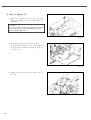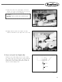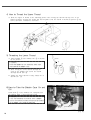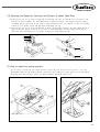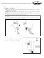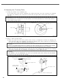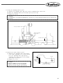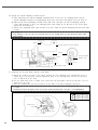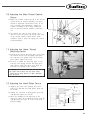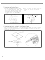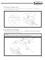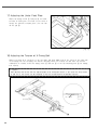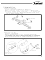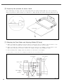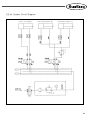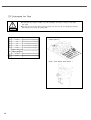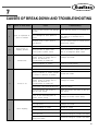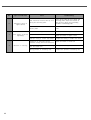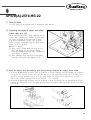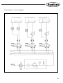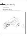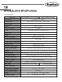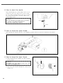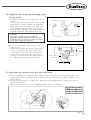
1
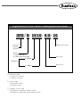
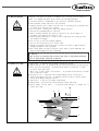
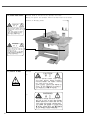
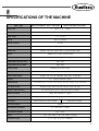
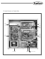
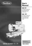
R
USER ’
S
MANUAL
SPS/B-2516 SERIES
SPS/A-2516 SERIES
Electronically Controlled
Pattern Sewing Machine
(Mechanical Part)
SUNSTAR MACHINERY CO., LTD.
1) FOR AT MOST USE WITH EASINESS,
PLEASE CERTAINLY READ THIS MANUAL
BEFORE STARTING USE.
2) KEEP THIS MANUAL IN SAFE PLACE
FOR REFERENCE WHEN THE MACHINE
BREAKS DOWN.
MME-040922
lity
a
u
tQ
Besst Pricevice
Be st Ser
Be
1. Thank you for purchasing our product. Based on the rich expertise and
experience accumulated in industrial sewing machine production, SUNSTAR
will manufacture industrial sewing machines, which deliver more diverse
functions, high performance, powerful operation, enhanced durability, and
more sophisticated design to meet a number of user’s needs.
2. Please read this user’s manual thoroughly before using the machine. Make
sure to properly use the machine to enjoy its full performance.
3. The specifications of the machine are subject to change, aimed to enhance
product performance, without prior notice.
4. This product is designed, manufactured, and sold as an industrial sewing
machine. It should not be used for other than industrial purpose.
R
SUNSTAR MACHINERY CO., LTD.
Organization of the Pattern Sewing Machine Model
SPS / B- 2 5 1 6 - H S - 2 0
Sunstar
Pattern
System
Feeding frame type
Series
A: Motor belt-type
B: Motor direct drive-type
X : 250mm
Stitch type
Sewing area
Y : 160mm
Material type
G:General material
H:Heavy material
Stitch type
S:Standard stitch
P:Perfect stitch
Feeding frame type
20:Pneumatic monolithic feeding frame
22:Pneumatic separately-driven feeding frame
Material type
CONTENT
1. Machine Safety Regulations
1)
2)
3)
4)
5)
6)
7)
Machine Transportation
Machine Installation
Machine Repair
Machine Operation
Devices for Safety
Caution Mark Position
Contents of Marks
6
6
6
7
7
8
8
2. Specification of machine
3. Structure of the machine
9
1) Name of each parts of machine
2) Inside structure of control box
10
11
4. Installation of machine
1) Environment for machine installation
2) Environment for electricity installation
3) Assembly of peripheral construction parts
12
12
12
5. Preparation before using the machine
1) Setting the voltage
2) How to supply oil
3) How to install the needle bar
4) How to thread the upper thread
5) Threading the lower thread
6) How to take the bobbin case on and off
7) How to adjust the tension of the upper thread and the lower thread
8) How to wind the lower thread
9) Adjusting the height of the presser foot
10) Disposing the waste oil
11) How to adjust the air pressure
12) Adjusting the speed for ascension and descent of upper feed plate
13) How to mount the sewing machine
14) How to attach and detach V-Belt (A Series)
15) Caution when using the floppy disks
6. How to repair the machine
1)
2)
3)
4)
Adjusting
Adjusting
Adjusting
Adjusting
the
the
the
the
height the needle bar
needle and the shuttle
lower shaft gear and the rocking shaft gear
spring on the upper side of the shuttle
15
16
17
18
18
18
19
19
20
20
20
21
21
22
22
23
23
24
24
5) Adjusting the presser foot devices
6) Adjusting the presser foot lifter cylinder
7) Adjusting accessories for thread delay
8) Adjusting accessories for the wiper
9) Adjusting the trimming parts
10) Adjusting the main thread control device
11) Adjusting the upper thread detecting device
12) Adjusting the hand pulley device
13) Adjusting the winding device
14) Adjusting the height of needle plate support cover
15) Adjusting the height of slider
16) Adjusting the X-guide bracket
17) Adjusting the under feed plate
18) Adjusting the tension of X-timing belt
19) Setting the X-Y origin
20) Adjusting the position of plastic blank
21) Mounting the Direct Motor and Adjusting Method(B Series)
22) Air System Circuit Diagram
23) Exchanging the Fuse
7. Cause of break-down and troubleshooting
8. SPS/B(A)-2516-HS-22
1)
2)
3)
4)
5)
Specification
Adjusting the angle of upper feed plate(Both right and left)
How to adjust the ascending and descending velocity of upper feed plate
How to use the pedal switch
Air system circuit diagram
25
27
27
29
30
33
33
33
34
34
35
35
36
36
37
38
38
39
40
41
43
43
43
44
45
9. SPS/B(A)-2516-GS-20(22)
1) Specification
2) How to hook the upper thread
46
46
10. SPS/B(A)-2516-HP(GP)-20(22)
1)
2)
3)
4)
5)
6)
Specification
How to attach the needle
How to thread the upper thread
How to thread the lower thread
Adjusting the spring on the upper side
Adjusting the moving knife and the fixed knife
47
48
48
48
49
49
11. Pneumatic hook-type cloth feed
1) Mechanical specifications
2) How to operate
50
50
1
MACHINE SAFETY REGULATIONS
Safety instruction on this manual are defined as Danger, Warning and Notice.
If you do not keep the instructions, physical injury on the human body and machine damage might be occurred.
Danger : This indication should be observed definitely. If not, danger could be happen during the installation,
conveyance and maintenance of machines.
Warning : When you keep this indication, injury from the machine can be prevented.
Notice : When you keep this indication, error on the machine can be prevented.
1-1) Machine Transportation
Danger
1-2) Machine Installation
Notice
Only trained and experienced people should treat the machine who are fully
understand the safety rules.
For conveyance, follow the below directions.
ⓐ More than two people to a minimum should convey the machine.
ⓑ For a protection of safety accident, wipe away the oil stained on machine.
Owing to the improper environment for machine installation, physical damages on
the human body and machine can be occurred. Please follow below conditions.
ⓐ When you unwrap the packing of the machine, try from above in order.
Especially careful of nails put into edges of wood box packing.
ⓑ Since dust and humidity can cause pollution and abrasion, you should install
airconditioner with regular cleaning.
ⓒ Put in a place of no direct ray of light.
If the machine is exposed in direct ray of light for a long time, transformation
of color and shape can be happened.
ⓓ To get enough space in case of repair, make the machine 50cm apart from the
right and left and back side of wall to a minimum.
ⓔ EXPLOSION HAZARDS
Do not operate in explosive atmospheres. To avoid explosion, do not operate
this machine in an explosive atmosphere including a place where large
quantities of aerosol spray product are being used or where oxygen is being
administered unless it has been specifically certified for such operation.
ⓕ The machines where not provided with a local lighting due to the feature of
machine. Therefore the illumination of the working area must be fulfilled by
end user.
[Refer] Details for installation of machine is described in‘4. Installation of Machine.’
1-3) Machine Repair
Danger
6
If you have any problems on the machine, troubleshooting should be handled by
the designated A/S engineers.
ⓐ Before cleaning and repairing machine, turn off the power and wait for 4
minutes until the machine comes to be completely discharged.
ⓑ You should not change the specification of machine and any part of machine
without consulting with our company. Those changes can threaten the safety of
machine during the operation.
ⓒ You should exchange from the used one into SWF guaranteed devices.
ⓓ After finishing troubleshooting, cover the all covers that are uncovered during
repairing.
1-4) Machine Operation
Notice
SPS/B(A)-2516 Series are made for industrial use to perform pattern sewing for
fabrics or its similar materials. Please observe the following principles.
ⓐ Read the manual to understand on the operation of machine perfectly.
ⓑ Wear suitable clothes and cap for safe operation.
ⓒ During operation, don’t make you body close to operating part of machine such
as needle, hook, take-up lever or pulley.
ⓓ Do not remove a safety plate and covers during operation
ⓔ Be sure the grounding lines in connected.
ⓕ Before opening electricity box such as control box, cut off the supply of
electricity and confirm if the switch is“off”.
ⓖ When inserting thread into a needle or before inspecting after sewing, be sure
the machine is stopped.
ⓗ Do not turn on the power during pedaling.
ⓘ Do not use several motor per a electric outlet.
ⓙ Install the machine apart from noise occurrence area such as high frequency
welding machines as far as possible.
ⓚ Be careful- When the upper feed plate comes down to press. Otherwise, the
finger or hand height be hurt at smacking.
[ Warning ]
Belt will crush or amputate finger or hand, keep cover in place before operating,
turn off power before inspecting or adjusting.
1-5) Devices for safety
Notice
ⓐ Safety label : It describes cautions during operating the machine.
ⓑ Thread take-up cover : It prevents from any contact between body and take-up lever.
ⓒ Servo Motor Cover(B Series) : It prevents from insertion of hands, feet or clothes
by Motor and Y-drive shaft.
ⓒ Belt cover·Y-drive shaft cover(A Series) : It prevents from insertion of hands,
feetor clothes by V-belt.
ⓓ Step Motor cover : It prevents from accidents during rotation of step motors.
ⓔ Label for specification of power : It describes cautions for safety to protect against
electric shock during rotating the motors.
ⓕ Safety plate : It protects eyes against needle breaks.
ⓖ Finger guard : It prevent from contacts between a finger and needle.
ⓗ Motor pulley cover(A Series) : It prevents from insertion of hands, feet or
clothes by V-belt.
ⓑ
ⓐ
ⓒ
ⓓ
ⓕ
ⓖ
ⓗ
ⓐ
ⓔ
7
1-6) Caution Mark Position
Caution mark is attached on the machine for safety.
When you operate the machine, observe the directions on the mark.
Position of Warning Mark
CAUTION
경 고
Do not operate without finger guard and
safety devices. Before threading, changing
bobbin and needle, cleaning etc. switch off
main switch.
손가락 보호대와 안전장치 없이 작동하지
마십시오. 실, 보빈, 바늘교환시나 청소전에는
반드시 주전원의 스위치를 꺼 주십시오.
WARNING
경 고
Hazardous voltage will cause injury.
Be sure to wait at least 360 seconds before
opening this cover after turn off main switch
and unplug a power cord.
고압 전류에 의해 감전될 수 있으므로 커버를
열 때는 전원을 내리고 전원 플러그를 뽑고 나
서 360초간 기다린 후 여십시오.
1-7) Contents of Marks
Caution
1)
CAUTION
경 고
Do not operate without finger guard
and safety devices. Before threading,
changing bobbin and needle, cleaning
etc. switch off main switch.
Warning
손가락 보호대와 안전장치 없이 작동하지 마
십시오. 실, 보빈, 바늘교환시나 청소전에는 반
드시 주전원의 스위치를 꺼 주십시오.
2)
WARNING
경 고
Hazardous voltage will cause injury.
Be sure to wait at least 360 seconds
before opening this cover after turn off
main switch and unplug a power cord.
고압 전류에 의해 감전될 수 있으므로 커버
를 열 때는 전원을 내리고 전원 플러그를 뽑
고 나서 360초간 기다린 후 여십시오.
8
2
SPECIFICATIONS OF THE MACHINE
Series type
Sewing Area
SPS/B-2516(Motor direct drive-type)
SPS/A-2516(Belt drive-type)
X : 250㎜ × Y : 160㎜
Sewing Speed
Max. 2,000spm (Stitch Length : 3㎜ or less)
Stitch Length
0.1~12.7㎜
Needle
DP×17, DP×5
Needle Bar Stroke
Hook
Bobbin Case
Bobbin
Presser Foot Stroke
41.2㎜
Semi-rotary Large Shuttle Hook
Bobbin Case for Semi-rotary Large Shuttle Hook
Bobbin for Large Shuttle Hook
Standard 4㎜ [0.5~10㎜]
Lifting Amount of Presser Foot
Max 20㎜
Lifting Amount of Feed Frame
Max 30㎜
Feeding System
Emergency Stop Function
Pattern Select Function
Memory
Memory Backup
2nd Origin Function
Maximum Speed Restriction
Number of Patterns
Safety Device
Main Motor
Power Consumption
Recommended Temperature
Recommended Humidity
Power
Pneumatic Pressure
Feeding by pulse motor
Available during sewing operation
Pattern No. can be selected from No.1 to No.999
3.5”Floppy Diskette (2HD)
The working point is stored in the memory when the machine stops abnormally.
Another origin point can be set by using jog key.
The maximum speed can be limited from 200 to 2,000spm
Max. 691 Patterns / Disk
Emergency Stop Function, Maximum Speed Limit Function
Direct Drive AC Servo Motor
550W Servo Motor
600VA
5℃~40℃(41℉~104℉)
20%~80%
1ф: 100~240V, 3ф: 200~440V, 50/60Hz
5~5.5 kgf/㎠ (0.49~0.54Mpa)
9
3
STRUCTURE OF THE MACHINE
1) Names of Each Parts of Machine
Emergency Stop Switch
Pause Switch
Arm
Thread Stand
Operation
Box
Power Switch
Control Box
Sewing pedal
Upper feed plate pedal
10
2) Inside Structure of Control Box
Floppy
Disk
Drive
Fan
Step
Motor
Drive
Board
Main
Shaft
Motor
Drive
Board
Power
Board
Transformer
IO Board
386 CPU Board
11
4
INSTALLATION OF THE MACHINE
1) Environment for Machine Installation
A. Do not use in a place where regularity voltage ± 10% is over for preventing from any accident by
wrong operation.
B. Check the indicated pressure of the devices that use atmospheric pressure such as the air cylinder to
prevent any accidents from occurring.
C. For safe operation of the machine, use the machine under the following conditions.
Surrounding Temperature During Operation : 5℃~40℃
Surrounding Temperature During Maintenance : -10℃~60℃
D. Humidity : Between 20~80%(Relative humidity)
2) Environment for Electricity Installation
A. Power voltage
·Use it within 10% change of regularity voltage.
·It is desirable to use the frequency of power within 1% of regularity frequency (50/60Hz)
B. Electric wave noise
To use with strong magnetic or high frequency goods, separate from the main power. Also do not
let the machine come close with it if possible.
C. Use low voltage when supplements or accessories are being adhered.
D. Be careful not to drop water or coffer inside of control box and motor.
E. Do not drop the control box and motor.
3) Assembly of Peripheral Construction Parts
A. Attach the X-motor cover, Y-motor cover, motor cover and belt cover to the back side of machine
with using fixing screws.
(In case of A series, place the belt cover and the X, Y cover only)
X-Motor Cover
Motor Cover
Belt Cover
Y-Motor Cover
[Fig. 1]
12
B. Attach the safety plate to the face plate.
ⓐ You should attach it for sure to prevent
from safe accident.
ⓑ Be careful when you start operation.
Otherwise, fingers or hand might be hurt at
the upper feed plate accidentally.
Face Plate
Safety Plate
[Fig. 2]
C. Connect a plug of pedal switch with control
box.
Pedal switch
[Fig. 3]
D. Install a thread stand on the table.
[ Caution ]
You can be hurt by the dropping device
during installation so be careful about it.
[Fig. 4]
13
E. Table leg holder
▶ Method
ⓐ Loosening the nut ① and turn and raise the label adjuster ② until the caster ③ is raced.
ⓑ After installation, fasten the nut ① and fix the label adjuster ②.
ⓒ With the bolt ④, adjust the height of table by loosening 8 different spots.
④
①
②
③
[Fig. 5]
[ Caution ]
For safety, work with the power cut off.
F. How to attach the accessories for air pressure control.
ⓐ Connect air hose ② to quick joint socket ①.
ⓑ Connect quick joint socket ① and quick joint plug ③.
ⓒ Open finger valve ④ and flow air in. Then, adjust the air pressure to 5~5.5kgf/㎠(0.49~0.54MPa).
[ Caution ]
When the air pressure goes down (under 4kgf/㎠), an error is indicated and the machine operation is stopped.
Error message : Err 24 (Low Pressure !)
[Note]
When the finger valve ④ is closed after use, the remaining air is rejected and the pressure
is adjusted to 0Mpa(0kgf/㎠ ).
②
①
③
④
[Fig. 6]
14
5
PREPARATION BEFORE USING THE MACHINE
1) Setting the Voltage
A. If a cover of electronically controlled pattern
sewing machine is taken off, inside contents
are as same as [Fig. 7].
B. Confirm the position of change connector of
power voltage on power board [Refer Fig. 7]
and transformer if they are properly selected
for input voltage like Table 1 and 2.
EX) If power voltage is 220 V:
The model of used transformer is“SPS-220”and it is normal for the
change connector of power voltage to be
placed on“JP5”.
※ Sticker for transformer model is attached to
the top side of transformer.
Model
Input Voltage
Position of change connector of power voltage
95V~105V
JP4
106V~115V
JP3
116V~125V
JP2
200V~230V
JP5
231V~245V
JP4
345V~415V
JP3
416V~480V
JP2
[ Table 1. Position of change connector of voltage ]
SPS/A-1306-X X - X X
SPS/A-1811-X X - X X
SPS/A-2516-X X - X X
100V~120V
″SPS-1306-110″
″SPS-1811-110″
″SPS-2516-110″
220V~440V
″SPS-1306-110″
″SPS-1811-110″
″SPS-2516-110″
Power Voltage
[Table 2. Model of used transformer according to the input power voltage]
C. Check if a power switch is for 1 phase and 3 phase.
D. If the setting of
and
is not proper, damage from breakdown can be occurred. If there is any
problem, follow below direction.
ⓐ If the position of change connector is wrongly placed :
① Separate the connector linked to transformer from CN7, CN8 and CN9 of power board.
② Insert the power change connector into a proper position on Table 1.
③ Reconnect the connector linked to transformer to CN7, CN8 and CN9 of power board.
ⓑ If the specification of used transformer is not in a accord with that of power switch, ask to the
place where you purchased for troubleshooting.
[ Caution ]
Before turning on the power switch, air should be filled with.
Floppy
Disk Drive
If an Input Power
voltage is Over 220V
Caution 1)
Step Motor
Drive Board
Back-Side Cover
Power Board
If an Input Power
Voltage is 110V
CN7 CN8
CN9
Main Shaft
Motor Drive Board
Back-Side Cable Cover
I/O Board CPU Board
Change Connector of Power Voltage
Transformer
Front-Side Cover
[ setting of change connector of power voltage ]
[Fig. 7]
15
2) How to Supply Oil
A. Check the amount of oil left in the oil tank
which is installed on the arm and supply oil
sufficiently.
[ Caution ]
Be sure to supply oil when operating the machine
for the first time or when the machine has not
been used for long time.
[Fig. 8]
B. As shown in the picture, move the feed
bracket in the direction of“A”and supply oil
into the bed oil window through the hole on
the bed cover.
[Fig. 9]
C. Supply oil into the hole in the upper part of
the arm.
[Fig. 10]
16
D. Open the hook cover and supply oil till the
shuttle race ring is surrounded by oil. Put the
hook cover back on after finishing.
[ Caution ]
For safety, keep the hook cover covered during
operating.
Shuttle Race Ring
Hook Cover
[Fig. 11]
E. Supply silicon oil into the silicon oil tank
which is installed on the right side of the arm.
Silicon Oil Tank
[Fig. 12]
3) How to Install the Needle Bar
Unfasten the needle fixing screw on the needle
bar. Then, with the needle groove facing forward,
push the needle until the upper end touches the
needle hole of the needle bar. Fix the needle in
with the needle fixing screw.
Screw
Needle
[Fig. 13]
17
4) How to Thread the Upper Thread
A. Hook the upper as shown in the following picture after setting the thread take-up lever at the
highest position. As with the needle bar thread guide, hook the thread as shown in picture ① for
heavy materials. (SPS/B(A)-2516-HS)
Fig. ①
[Fig. 14]
5) Threading the Lower Thread
A. Insert bobbin ① into bobbin case ② as shown
in the picture.
[ Caution ]
Insert the bobbin to turn clockwise when seen
from behind the bobbin case.
25mm
③
②
①
B. After setting the lower thread through the
crack of the bobbin case, insert the thread
through thread hole ③.
C. Adjust the lower thread to hang 25mm out of
thread hole ③.
[Fig. 15]
6) How to Take the Bobbin Case On and
Off
Hold knob ① of the bobbin case and push into
the shuttle until a click sound is heard.
[ Caution ]
If you start operating the machine when a bobbin
case is not perfectly installed, thread can be tangled
of the bobbin case would be protruded.
①
Bobbin Case
[Fig. 16]
18
7) How to Adjust the Tension of the
Upper Thread and the Lower Thread
A. Adjusting the tension of the upper thread
When the tension adjusting nuts ③ and ④, of
thread tension adjusting unit ① and subtension adjusting unit ②, are turned clockwise
the upper thread is tightened. And loosens
when turned the other way around.
[Fig. 17]
B. Adjusting the tension of the lower thread
The lower thread becomes tight when tension
adjusting screw ① is turned clockwise, as
shown in the picture. When the screw is
turned the other way the lower thread is
loosened.
①
[Fig. 18]
8) How to Wind the Lower Thread
A. Insert the bobbin into thread winding drive shaft ② on thread winding base ① which is installed
on the upper top.
B. Operate the machine after sticking the thread winding lever ③ to the bobbin.
C. When the thread winding lever is separated from the bobbin, cut the bobbin thread with thread
winding mes ④.
②
④
③
①
[Fig. 19]
19
9) Adjusting the Height of the Presser Foot
A. Unfasten presser foot screw ① with the needle
bar at the lowest position.
B. Adjust the height so that the presser foot
bottom comes 0.5mm(the thickness of the
thread used)above the sewing material.
Then, tighten the screw.
[ Caution ]
After adjusting the height of presser foot, confirm
the position of wiper
· Too excessive gap can cause jumping
· Insufficient gap can cause a failure in thread
adjustment
0.5㎜
[Fig. 20]
10) Disposing the Waste Oil
Oil Hose
When the oil receiving container at the bottom
of the table is full, take it off to empty.
[ Caution ]
Spread out some fabrics or papers on the floor
when you attach or remove the oil receiving
container
Oiler
[Fig. 21]
11) How to Adjust the Air Pressure
+
-
Pull the adjustment handle on the upper part
of the filter controller, which is attached to
the back of the table, up as shown in the
picture. When the handle is turned clockwise
the pressure goes up and goes down when the
handle is turned in the opposite direction.
Adjust to the appropriate pressure(5~5.5kgf/
㎠) indicated in the pressure gauge, then press
and fix the adjustment handle into its place.
[Fig. 22]
20
12) Adjusting the Speed for Ascension and Descent of Upper Feed Plate
A. Like the fig. ⓐ, if you turn a handle ② on reducing valve ① of solenoid valve attached to the
bottom of table clockwise, the ascending speed of upper feed plate and support pressure during
ascending will be increased, if you turn it counterclockwise, they are reduced, so that you should
adjust it to be proper speed and fix them with fixing nut ③.
B. Like the fig. ⓑ, if you turn a handle ⑤ of sped controller ④ clockwise, the descending speed of
upper feed plate will be reduced, if you turn it counterclockwise, the descending speed will be
increased. After adjusting it to be proper speed, fix it with fixing nut ⑥.
②
③
①
S1P
S2P
⑤
⑥
④
S3R
(Right)
Solenoid valve
[ ⓐ ]
[ ⓑ ]
S3L
(Left)
[Fig. 23]
13) How to mount the sewing machine
If you repair or mount up the sewing machine, remove the belt after the above process - 13), and
disassemble Table(left)③, Table(right)④, and Presser Foot Support Cover⑤. And if you works during
mounting the sewing machine, please use Frame Support Bracket⑥ without fail.
[Fig. 24]
[Fig. 25]
21
14) How to attach and detach V-Belt (A Series)
A. Loosen a fixing screw of Belt Cover① to disassemble Belt Cover from the sewing machine.
B. Loosen a fixing nut② of Motor to rise it up to the arrow.
C. When V-Belt tension gets loosened, remove V-Belt.
[Fig. 27]
[Fig. 26]
15) Caution When Using the Floppy Disks
Observe the following principles thoroughly when you treat floppy disks.
[ Caution ]
Use the identified floppy disks after formatting when you get floppy disks in market.
ⓐ Do not put floppy disks near magnetic-related materials
such as television.
①
ⓑ Keep away from overheat, humidity or direct ray of light.
ⓒ Do not put any heavy material on a floppy disk.
ⓓ During formatting or inputting and outputting floppy disks,
do not take out a floppy disk from a disk drive.
ⓔ Do not open a cover of floppy disk.
ⓕ If a write protect tab is opened, you can’t input data in a
disk
ⓖ If you repeat read and write in a disk many times, error
can be occurred in a disk.
②
ⓗ It is safe to keep important design data in two disks.
① Shuttle
22
② Write protect tab
6
HOW TO REPAIR THE MACHINE
Caution
The machine is set to be the best condition at the factory. Do not make any discrete adjustments
on the machine and replace accessories approved by the company only.
1) Adjusting the height of the needle bar
①
When the needle bar is at its lowest position,
unfasten the needle bar holder screw ①. Adjust the
desired height by making the specified upper
carving line fit in with the needle bar bushing.
Then, tighten the needle bar holder screw ① back
on firmly.
DP×5
DP×17
#22 and
above
DP×17
#22 and below
[Fig. 28]
2) Adjusting the needle and the shuttle
A. Have the lower carving line for the needle that
is applied when the needle bar goes up fit in
with the lower side of the needle bar bushing as
shown in the picture.
Needle Bar
Lower Bushing
DP×5
DP×17
#22 and
above
DP×17
#22 and below
[Fig. 29]
B. After unfastening the shuttle drive screw ①, open the inner hook pressure bar ② left to right and remove the
shuttle lace ring ③ from the (large) shuttle ④.
C. Make the shuttle hook point
accord with the center of the needle. And make the needle and the front
facet of the shuttle drive
connect each other to prevent the needle from curving. Then, tighten the drive
screw ① firmly.
D. After unfastening the (large) shuttle screw ⑤, turn the large hook adjustment shaft ⑥ to the left to right
and adjust the (large) shuttle ④ so that the needle and the shuttle hook point
is 0.05~0.1mm apart from
each other.
E. After adjusting the (large) shuttle ④ in place, adjust the rotary direction of the (large) shuttle ④ so the
needle and the (large) shuttle ④ is 7.5mm apart from each other. Then, tighten the (large) shuttle screw ①.
[ Caution ]
For safety, make sure all the screws are tightened firmly after adjusting the (large) shuttle.
0mm
→
7.5mm
→
0.05~0.1mm → →
⑤⑥
②
②
④
①
③
[Fig. 30]
23
3) Adjusting the Lower Shaft Gear and the Rocking Shaft Gear
A. Unfasten screws ① and ②.
B. While having the upper shaft turning, move the rocking shaft gear in the direction of the arrow to
the position where it will move easily without load.
[ Caution ]
The machine may not operate when the rocking shaft gear in not in the right position.
C. Have the oscillator shaft collar(right) stick to the bed surface , and then tighten the collar screw
②.
D. Turn the oscillator shaft collar(right), still sticking to the bed surface , in the direction of the
arrow and make adjustments so the end of the shuttle drive will rotate smoothly with the
backlash of under 0.1mm.
[ Caution ]
If there is too much backlash the machine may make more noise than usual during operation. And if
there is not enough backlash, the machine may not operate.
E. Tighten screw ① back on firmly.
Backlash : 0.1mm and below
Oscillator Shaft
Collar(R)
②
①
[Fig. 31]
4) Adjusting the Spring on the Upper Side of the Shuttle
After removing the lower feed plate and the needle plate from the machine, unfasten the screw of the
spring on the upper side. Then, adjust the spring on the upper side of the shuttle so that the backside of
the needle and comes to point
in the vertical direction, and the center of the needle will come to the
middle of interval
horizontally. After the adjustment is done, tighten the screw back on firmly.
[ Caution ]
The thread may be disconnected or the thread strand may be unfastened if there are scratches or if the surface
is rough around the spring groove on the upper side of the shuttle. Always check the surface of the spring
before operating the machine.
①
①
①
①
①
[Fig. 32]
24
5) Adjusting the Presser Foot Devices
A. Conform the end of presser foot operating cam to the center of punched mark, and conform the cam’s
punched line to the punched mark of upper axis, and then tighten Clamp①.
[Cautions]
If the presser foot operating cam is improperly positioned, The up-and-down moving of
presser foot is in inconformity, therefore the presser foot may collide with the needle bar.
①
Engraved
Point
Upper
Shaft
[Fig. 33]
B. Project the presser bar about 17㎜ from the
presser bar holder, check if the needle passes
through the center of presser foot, then tighten
Clamp①.
→
17mm
→
Presser
Bar
①
Presser Bar
Holder
Presser
Foot
[Fig. 34]
C. Loosen Fork Crank Clamp①, and place the single screw② of presser foot link to the right of the
adjusting arm.
D. Conform the fixing single screw③ of presser foot moving link to the end④ of position link stopper.
[ Caution ]
If there is space between presser bar handle and presser bar bush, interference and noise is occurring
during machine operation. Screws are not fastened tightly after adjustment; it can cause breakage during
operation.
E. To set up 4㎜ of the interval between Presser Bar Holder and Presser Bar Bushing, rise up the presser
bar and tighten Fork Crank Clamp①.
25
F. Check the tightening status of screws, and adjust the presser foot’
s stroke.
[Cautions]
If there is no interval between Presser Bar Holder and Presser Bushing, the machine may be
interfered during its operation. If the handle is completely tightened, the machine may be
damaged during its operation.
Presser Foot
Adjusting Arm
②
①
③
Presser Bar Bush
4mm
→→
④
Presser Bar
Holder
[Fig. 35]
G. Adjustment of Presser Foot Stroke(Adjustment
of Presser Foot UP/DOWN Motion)
After unfastening stud screw① of presser foot
adjusting arm, placing it to A direction, presser
foot stroke increases. Placing to direction B,
stroke decreases.(It is set to 4mm at the
moment of factory shipping).
B A
①
[Fig. 36]
26
6) Adjusting the Presser Foot Lifter Cylinder
A. The distance between the hole center of cylinder knuckle ① and the hole center of presser foot
lifter cylinder ② to be 163.2±0.2mm to maximum.
B. If you turn a handle ④ of speed controller ③ on presser foot lifter cylinder ② clockwise, the
ascending speed of presser foot will be reduced, if you turn it counterclockwise, they are increased,
so that you should adjust it to be proper speed and fix them with fixing nut ⑤.
C. If you turn a handle ⑦ of speed controller ⑥ on presser foot lifter cylinder ② clockwise, the
descending speed of presser foot will be reduced, if you turn it counterclockwise, they become
increased, so that you should adjust it to be proper speed and fix them with fixing nut ⑧.
①
⑥
②
③
118.2±0.3㎜
⑦
⑧
④
⑤
163.2±0.2㎜
[Fig. 37]
7) Adjusting The Parts for Thread Release
A. How to set the thread release notch
Place the notch so that the right side of the
oval share of the thread release notch ① touches
circumference of the notch screw ②, and then
fix with a screw.
[ Caution ]
The remaining amount of thread may not be
enough or not be regular and the thread may be
unfastened from the needle if the notch is not set
in the right position.
②
①
Thread
Trimming Cam
[Fig. 38]
27
B. How to set the thread release stopper
ⓐ Remove the thread release return spring.
ⓑ After unfastening the thread release stopper screw, adjust the trimming drive link and the thread
release lever pin 0.3mm apart from each other. Then, attach the arm to the thread release stopper
completely. When the thread release stopper is pushed to the right, the space between the
trimming drive link and the thread release lever pin is reduced. And it is enlarged when the
stopper is pushed to the left.
ⓒ Hang on the thread release return spring.
[ Caution ]
Use a tool when removing or attaching the thread release spring to prevent accidents.
Thread Release
Lever Pin
Thread Trimming
Driving Link
Return Spring
0.3mm
→→
Thread Release Stopper
Screw
Widen
Narrow
[Fig. 39]
C. How to adjust the opening capacity of the thread guide dish
ⓐ Unfasten the thread release control plate screw.
ⓑ Open the thread guide dish by operating the trimming devices.
ⓒ Adjust the opening capacity to 0.6~0.8mm for normal material and 0.8~1mm for heavy material. To
increase the opening capacity, widen the angle between the thread release plate and narrow the angle
to reduce the opening capacity.
ⓓ Tighten the screw after the adjustment.
[ Caution ]
If the dish is not opened appropriately, the amount of remaining thread may be not enough or not
regular, and the dish may not be closed completely.
Widen
Narrow
→ → Floating Amount
Screw
Thread Tension Adjusting Plate
To Thread Tension Adjusting Ass’y
To Tension Release Link
28
[Fig. 40]
8) Adjusting Accessories for the Wiper
A. Adjusting the wiper position
ⓐ Unfasten the wiper rotary shaft collar screw ① and the wiper crank screw ② when the needle tip is
19.5mm above the throat plate.
ⓑ Press the wiper rocking link ③, then adjust the wiper shaft ④ so the wiper and the needle is about
10mm apart from each other.
ⓒ Tighten the wiper rotary shaft collar screw ① and the wiper crank screw ②.
ⓓ Unfasten the wiper screw ⑤ and adjust the wiper so that the end of the wiper is about 1mm apart
from the needle end. Then, tighten the screw back on firmly.
[ Caution ]
If the wiper is not placed in the right position, the wiper may collide with the presser foot or needle
during the operation, and the wiper may not move properly.
③
Push
②
⑤
①
④
→
→→
1mm
Needle
19.5mm Plate
→
→ → 10mm
[Fig. 41]
B. Wiper operating switch
If you want to use the wiper, press the wiper
operating switch
─, if you don’t, presser
O.
the press the wiper operating switch
Wiper On/Off Switch
Wiper Off
Wiper On
[Fig. 42]
29
9) Adjusting the Trimming Parts
A. Setting the position of the trimming cam
Set the upper shaft collar and the trimming cam 2.5mm apart from each other and place the trimming
cam where the trimming cam carving line accords with the upper shaft carving point. Then, tighten
screw ①.
[ Caution ]
If the trimming cam is not placed in the right position, the trimming operation may not be made correctly
in the machine may be struck.
Thread Trimmer Cam
Engraved Line
2.5mm
→ →
Upper Shaft
Engraved Line
Upper Shaft
Upper Shaft Collar
①
[Fig. 43]
B. How to adjust the link stopper
ⓐ With the needle bar in its lowest position, check if there is enough space between the trimming cam
roller and both ends of the trimming cam when the trimming drive link is pushed in the direction of
the arrow ( ) within the trimming cam moving part.
[ Caution ]
If there is not enough space between the trimming cam roller and both ends of the trimming cam, trimming
may not be operated correctly or the machine may be struck when beginning to sew or trimming.
ⓑ Make the end of the link stopper screw touch part
of the trimming link stick when the trimming
cam roller is inserted into the trimming cam moving part. Then, tighten the nut.
[ Caution ]
If the position is not set appropriately, the return to the previous point after trimming may be delayed
and the first stitch may not be tight enough.
Thread Trimming Driving Link
Thread Trimmer
Cam Roller
Clearance
Clearance
Thread Trimmer Cam
Thread Trimmer
Connecting Rod
Link Stopper Screw
Link Stopper Screw
Nut
Thread Trimmer Connecting Rod
[Fig. 44]
30
C. Setting the trimming shaft in place
ⓐ Unfasten the trimming drive link screw and the trimming shaft collar screw.
ⓑ Make the trimming shaft tip accord with part
of the arm.
ⓒ Tighten the screws.
[ Caution ]
If the position is not adjusted appropriately, trimming may not be operated correctly or the machine may
be struck.
Thread Trimmer Cam
Thread Trimming
Driving Link
Thread Trimmer Shaft
Screw
[ Caution ]
If the link stopper is not set in the right
position, trimming may not be operated
correctly and the machine may be struck.
0.3mm
Thread
Trimmer
Driving
Link
Screw
→
→
D. Unfasten the link stopper in place
ⓐ Unfasten the trimming drive link stopper
screw while trimming is not operated and
have the trimming drive link and the
trimming drive link stopper notch 0.3mm
apart from each other.
ⓑ Tighten the screw.
→→
[Fig. 45]
0.3mm
Thread Trimmer
Driving Link Stopper
[Fig. 46]
31
E. Setting the thread trimming solenoid in place
ⓐ After unfastening the thread trimming solenoid bracket screw, have the trimming shaft and the
thread trimming solenoid rotary link 0.5mm apart from each other and tighten the screw back on.
ⓑ Unfasten the thread trimming solenoid rotary link screw and drive the thread trimming solenoid
rotary link manually to move the trimming shaft collar 6.8mm in the direction of the arrow. Then,
tighten the screw back on.
ⓒ Check if the trimming shaft collar returns to its place when the thread trimming solenoid rotary link
returns.
[ Caution ]
If the position is not set right, the trimming return or the thread delay may be delayed to bring poor
sewing quality.
Screw
Thread Trimmer Solenoid Bracket
Solenoid
Thread Trimming
Rotation Link
Screw
→→
0.5mm
Thread Trimming Rotation Link
Thread Trimmer Shaft
→ →
6.8mm
[Fig. 47]
F. Adjusting the moving Knife and the fixed Knife
ⓐ When the needle bar stops at the upper position, use the trimming lever adjustment screw to
adjust space A between the thread separation point of the moving knife and the needle plate
hole as indicated in the table.
ⓑ Use the fixed knife screw to adjust space B between the fixed knife and the needle plate cover as
indicated in the table.
ⓒ After the adjustment, check the position of the knife by manual trimming operation.
[ Caution ]
Trimming may not be operated or there may not be enough remaining knife if the knife is set inappropriately.
G
H
Knife
A
B
4.5mm
5.3mm
1~1.2mm
1~1.2mm
B
→
→
Needle Plate
Cover
→
→A
Moving Knife
[Fig. 48]
32
10) Adjusting the Main Thread Control
Device
A. When the tension control nut ① of the thread
control device is turned clockwise, the upper
thread is tightened and becomes loose as the
nut is turned counterclockwise. Adjust the
tension according to the sewing conditions
such as material, thread, number of stitches
etc.
B. To tighten the take-up lever spring, use a
driver to turn the groove ② on the edge facet
of the thread tension control device shaft
clockwise. And to make the spring lax, turn it
counterclockwise.
①
Thread Take-up
Spring
②
[Fig. 49]
11) Adjusting the Upper Thread
Detecting Device
A. Unfasten the thread detecting plate screw with
the thread off the take-up spring and make
the take-up lever spring touch the detecting
plate. Then, tighten the screw.
B. Be sure to adjust the detecting plate so the
take-up lever spring and the detecting plate
will connect with each other even when the
take-up lever spring stroke changes.
Thread Take-up Spring
Thread Detecting
Plate
Screw
[ Caution ]
Be careful not to touch with any other metals
except take-up lever spring. If it does, detection
may be failed.
[Fig. 50]
12) Adjusting the Hand Pulley Device
A. Tighten the screw after putting the hand
pulley gear
and the hand pulley shaft tip
in accord.
B. Adjust the variation of hand pulley gears
and
and tighten the screws.
C. Move the bushing in the direction of the
arrow to reduce the backlash between gears
and
when the roller is on the end of the
pulley bushing.
Upper Shaft
Hand Pulley
Bushing
Hand Pulley Shaft
Roller
[Fig. 51]
33
13) Adjusting the Winding Device
A. To adjust the winding capacity of the bobbin,
use the beginning position of the winding control
plate, and after unfastening the screw, turn the
plate in direction A for large winding capacity
and turn in direction B for small winding
capacity.
B. Place the winding drive wheel 0.5mm away
from the hand pulley gear and tighten the
screw.
Bobbin
A
0.5mm
Bobbin Winder
Driving Wheel
→ →
Upper Shaft
B
Bobbin Winder Adjusting Plate
[Fig. 52]
[Fig. 53]
14) Adjusting the Height to Needle Plate Support Cover
Loose the cover bracket fastening screw ① of needle plate support and the cover bracket A fastening
screw ② of needle plate support, then fix the distance to be 0.3mm between the needle plate and
cover of needle plate support.
Cover of Needle
Plate Support
Needle Plate
Cover of Needle Below 0.3mm
Plate Support
[Fig. 54]
34
15) Adjusting the Height of Slider
Loosen the fixing screw ① of slide holder and adjust the gap of slider holder to be 0.3±0.2mm by
turning the slider holder with a spanner.
Pressure Plat
Pressure Plate
3.5±0.2mm
Slider
Slider Holder
①
①
[Fig. 55]
16) Adjusting the X-Guide Bracket
Incline the guide bracket to the direction of“ → ”to the maximum manually. Loosen the fixing
screws for Y-transfer shaft ① and adhere the side of y-transfer shaft and the side of X-guide shaft
bracket closely, then fix the Y-transfer shaft ①.
[ Caution ]
After fixing the Y-transfer shaft screws ①, the X-guide shaft bracket should not move at all by load
even though when you move manually the feed bracket to the right and left.
②
Y-Transfer Shaft
Y-Axis Shaft
Y-Guide Shaft Bracket
①
[Fig. 56]
35
17) Adjusting the Under Feed Plate
When the fixing screws ① and pin ② are fixed,
location of under plate is settled. If you want to
change the position of under plate, you can take
off the pin ②.
[Fig. 57]
18) Adjusting the Tension of X-Timing Belt
When you make X-Y rail move to the left limit and hang 500g load on the center in the right side
of X-timing belt, the X-timing belt will be drooping about 1.6~1.8mm. At this time, for the fine
adjustment of tension, loosen the fixing screw ① and nut ② to use the adjusting bolt ③ for timing
belt tension.
[ Caution ]
After adjusting the tension with the adjusting bolt ③ for timing belt tension, if you fasten the fixing screw
① and nut ②, the tension can be changed, so that you should confirm the bending capacity.
500g
1.6~1.8mm
X-Timing Belt
②
①
③
[Fig. 58]
36
19) Setting the X-Y Origin
A. How to set the X-shaft origin
ⓐ Separate the under feed plate from X-fixing cover and transfer cover.
ⓑ Move the center of upper feed plate to be located the center in the direction of X shaft.
ⓒ As seen in the below figure, release the 2 fastening screws ① of X shaft origin sensor bracket
and make the X-sensor plate that is adhered to X-Y transfer devices locate the center of
sensor, then fasten the screws with (+) driver.
X-Origin Sensor Bracket
①
X-Sensor Plate
[Fig. 59]
B. How to set the Y-shaft origin
ⓐ Separate the set the Y-shaft origin.
ⓑ Move the center of upper feed plate to be located the center in the direction of Y shaft.
ⓒ As seen in the below figure, release the 2 fastening screws ① of Y transfer shaft sensor linking plate
and confirm if the Y-sensor transfer plate and sensor works independently, then the fixing screws ①.
ⓓ Adjust the Y direction origin with the fixing screws ② of Y-transfer shaft sensor fixing plate.
Y Limit Sensor
Y Origin Sensor
①
Y Transfer
Shaft Sensor
Linking Plate
②
Y Sensor Transfer Plate
Fixing Plate of Y
Transfer Shaft Sensor
[Fig. 60]
37
20) Adjusting the position of plastic blank
After unfastening the fixing screws ① and pressing down the plastic blank handle ② to the A direction,
adjust the position of plastic blank to be adhered to a hinge pin ③, then fasten again the fixing screw ①.
②
①
③
②
Plastic Blank
①
[Fig. 61]
21) Mounting the Direct Motor and Adjusting Method (B Series)
A. When you mount the coupling on the servo-motor, fit the screw No.1 of coupling to the flat surface of the
servo motor shaft and make the clearance between the coupling and servo motor 0.7mm.
B. When you mount the coupling on the upper shaft, fit the screw No.1 of coupling to the flat surface of the
upper shaft and make the clearance between the coupling and upper shaft bushing(R) 2mm.
C. After mounting both coupling, check the positions of each screws to the aligned.
※ If the positions of each screws are not aligned, the needle does not stop normal position.
Screw NO.1
Servo Motor
Upper Shaft
Upper Shaft
Rear
Bushing
Flat
Surface
ARM
38
2
Coupling
0.7
[Fig. 62]
22) Air System Circuit Diagram
Presser Foot Cylinder
Feed Frame Cylinder (R)
Feed Frame Cylinder (L)
39
23) Exchanging the Fuse
■To prevent from electric shock, turn off the power and wait 5 minutes, then open
the cover.
■Be sure to turn off the power and exchange into the fuse of the designated quantity
after opening the cover of control box.
Caution
No
Quantity
①
②
③
④
⑤
0.5A
For the Protection of thread sensor
3A
For the Protection of control power
⑥
⑦
⑧
Use
7A
For the Protection of actuator
8A
For the Protection of step driver
0.5A
For the Protection of step-aux
INPUT 110V 7A
INPUT 220V 5A
< Power Board >
For the Protection of main power
6.3A
For the Protection of servo motor
0.5A
For the Protection of servo motor drive
⑥
< Main shaft Motor drive Board >
40
⑤
④
③
②
①
7
CAUSES OF BREAK-DOWN AND TROUBLESHOOTING
No.
Typed of Break-down
Cause
Troubleshooting
Loosing of belt tension and damage
Adjust the belt tension or exchange it
on belt
1
2
3
Error on operation or
drive of machine
Bad position of
stopping position
Needle bent
Fuse shortage for main power or
circuit
Check the fuse shortage of main shaft
drive motor in a controller box or
exchange it
Deviation from Y and Y limit of
feed bracket
Move the feed bracket to normal place
(inside limit switch)
Slackness of main drive belt
Adjust the belt tension
Wrong position of upper shaft
sensor plate or photo sensor
Adjust the position of upper shaft sensor
plate or exchange the photo sensor
Damage on needle(Bending of
needle, cracks on needle hole or
groove, and abrasion or
transformation of needle tip)
Exchange the needle
Wrong installation of needle
Install the needle properly
Contact of needle with shuttle
Adjust the distance properly between a needle and shuttle
Wrong insertion of thread
Insert the thread properly
Wrong installation of needle (Height
Reinstall the needle
of needle or direction of needle)
4
5
Thread is cut
Stitch skipping
Damage on needle(Bending of
needle, cracks on needle hole or
groove, and abrasion or
transformation of needle tip)
Exchange the needle
Excessive tension of upper thread and under thread
Adjust the tension
Excessive tension and stroke of
take-up lever spring
Adjust the tension and stroke of take-up
lever spring
Crack on the controlling hole of
shuttle surface spring
Exchange the shuttle surface spring
Use of bending needle
Exchange the needle
Use of improper sized needle compared
with using thread
Exchange the needle
Wrong installing of needle
Reinstall of needle
Improper timing for a needle and shuttle
Reinstall the timing for a needle and shuttle
Large interval between a needle groove
and shuttle point
Excessive tension of take-up lever
spring and stroke
Reinstall the timing for a needle and shuttle
Reinstall the timing for a needle and shuttle
41
No.
6
7
Type of Break-down
Ineffective sense of
upper thread
Poor quality of thread
tightening
Cause
Troubleshooting
Clean up the take-up lever spring and
Bad connection between take-up lever detecting plate. Adjust the tension of
take-up lever spring and connecting
spring and detecting plate
condition of detecting plate
Bad connection of wire with thread
sensor plate
Reconnect the wire with thread sensor
plate
Weak tension of upper thread
Adjust the tension of upper sensor
Weak tension of under thread
Adjust the tension of upper sensor
Improper timing of needle and shuttle
Readjust the timing of needle and shuttle
Slackness of exchange tension
Adjust the tension of fixed mes
between moving mes and fixed mes
8
Mistakes of trimming
Groove abrasion on blade of moving
Exchange the moving and fixed mes
mes and fixed mes
Wrong position of trimming cam
42
Readjust the position of trimming cam
8
SPS/B(A)-2516-HS-22
1) Specification
It is the same as the specification of SPS/B(A)-2516-HS-20.
2) Adjusting the angle of upper feed plate
(both right and left)
When the upper feed plate (both right and left) is
parallel with a needle plate, pressure to press down
the sewing materials of the front side of upper
feed plate is insufficient. In that case, keep the
upper feed plate (both right and left) 3mm above
surface of the needle plate.
▶ How to adjust
ⓐ After loosen a cramp fixing screw ① of feed
plate and linking nut ③, turn the linking
screw ② clockwise, the front side of upper feed
plate comes to descend.
ⓑ After adjusting angle, fasten the cramp fixing
screw ① of feed plate and linking nut ③.
[Fig. 63]
3) How to adjust the ascending and descending velocity of upper feed plate
A. As shown in Figure63ⓐ, clockwise turn the holder② of pressure-reducing valve① including the solenoid
attached to the bottom of table, then the ascending speed and supporting pressure upon ascending get
increased. Counter clockwise turn it, they get down. Adjust the proper speed and pressure, and fix it
with a fixing nut③ (Initial Pressure Upon Delivery : 2.0~2.5㎏f/㎠)
B. As shown in Figure63ⓑ, clockwise turn the holder⑤ of speed controller④, the its descending speed gets
reduced. If counter turn it, the ascending speed gets increased. Then adjust the proper speed to fix with
a fix nut⑥.
[ ⓐ ]
[ ⓑ ]
②
③
⑥
⑤
①
④
S3R
S3L
Solenoid Value
[Fig. 64]
43
4) How to use the pedal switch
A. Check the parameter, related to general sewing(function no.60), is set to“2”. If not, please set the
parameter to“2”.(Refer to 7.29) Change of parameter related to general sewing).
B. The pedal switch has three pedals, the right one ① moves the right upper feed plate, the intermediate one ②
moves the left upper feed plate and the left one ③ makes the sewing machine start.
C. Application (Basic)
ⓐ If you step on the intermediate pedal ②, the left upper feed plate descends to hold the sewing material.
ⓑ When you step on the right pedal ①, the right upper feed plate descends to hold the sewing material.
(When you step on the pedal ① again, the right upper feed plate ascends to the initial position)
ⓒ When both of the upper feed plates are descended, if you step on the left pedal ③, the machine starts.
※ This model does not have 2-step stroke option.
③
②
①
③
②
①
③
②
①
[Fig. 65]
D. In
ⓐ
ⓑ
ⓒ
※
case of using monolithic feed frame.
Set the parameter, related to general sewing(function no. 60), to“0”.
If you step on the intermediate pedal ②, the upper feed plate descends to hold the sewing material.
After the upper feed plate descends, if you step on the left pedal ③, the machine starts sewing.
This model does not have 2-step stroke option.
③
②
①
③
②
①
[Fig. 66]
44
5) Air System Circuit Diagram
Presser Foot Cylinder
Feed Frame Cylinder (R)
Feed Frame Cylinder (L)
45
9
SPS/B(A)-2516-GS-20 (22)
1) Specification
The same as SPS/B(A)-2516.
2) How to thread the upper thread
After placing the thread take-up at the highest position hook the thread as indicated in the picture
below. Hook the thread as shown in picture ⓐ for the needle bar thread guide.
ⓐ
46
10
SPS/B(A)-2516-HP(GP)-20(22)
1) Specification
Series type
Sewing Area
SPS/B-2516(Motor direct drive-type)
SPS/A-2516(Belt drive-type)
X: 250mm × Y: 160mm
Sewing speed
Max. 2,000spm (Stitch Length : 3mm or less)
Stitch Length
0.1~12.7mm
Needle
Needle Bar Stroke
Hook
Bobbin Case
Bobbin
Presser Foot Stroke
DP×17, DP×5
41.2mm
Semi-rotary large hook (for perfect stitch)
Bobbin case for semi-rotary large hook (for perfect stitch)
Bobbin for large hook
Standard 4mm [0.5~10mm]
Lifting Amount of Presser Foot
Max. 20mm
Lifting Amount of Feed Frame
Max. 30mm
Feeding System
Feeding by pulse motor
Emergency Stop Function
Available during sewing
Pattern Select Function
Memory
Memory Backup
2nd Origin Function
maximum Speed Limit
Number of Patterns
Safety Device
Main Motor
Power Consumption
Recommended Temperature
Recommended Humidity
Power
Pneumatic Pressure
Pattern No. can be selected from no.1 to no.999
3.5″Floppy Diskette (2HD)
The working point is stored in the memory when the machine stops abnormally
Another origin point can be set by using jog key
The maximum speed can be limited from 200 to 2,000spm
Max. 691Patterns/Disk
Emergency stop function, maximum speed limit function.
Direct Drive AC Servo Motor
550W Servo Motor
600VA
5℃~40℃ (41℉~104℉)
20%~80%
1ф : 100~280V, 3ф : 200~400V, 50/60Hz
5~5.5kgf/㎠ (0.49~0.54㎫)
47
2) How to attach the needle
After unfastening the needle fixing screw on the
needle bar, have the long groove of the needle
face the back and push the needle till it touches
the needle insertion hole and then tighten the
needle fixing screw.
[ Caution ]
For type SPS/B(A)-2516-HP(GP)-20(22) the needle
is inserted in the opposite directions of
SPS/B-2516-HS(GS)-20(22) machine.
Screw
Needle
[Fig. 67]
3) How to thread the upper thread
After placing the thread take-up at the highest position, hook the thread as shown in the picture
below.
[Fig. 68]
4) How to thread the lower thread
A. Insert bobbin
in the picture.
into bobbin case
as shown
[ Caution ]
The bobbin must turn clockwise when seen from
the back of the bobbin case.
B. Place the lower thread through the crack in the
bobbin case.
[Fig. 69]
48
5) Adjusting the spring on the upper side
of the shuttle
A. Adjusting the spring on the upper side of the
shuttle.
After removing the lower feed plate and the needle
plate from the machine, unfasten the upper side
spring screw. Place the spring on the upper side
of the shuttle so that the center of the needle
meets point
vertically, and is 1mm apart from
point
horizontally. Then tighten the screw.
①
①
1mm
[ Caution ]
If the surface around the spring is rough or
scratched, the thread may be disconnected or the
thread strand may be unfastened. Always check the
surface before operating the machine.
①
①
Upper
Thread
Loop
Adjusting
Plate
Upper Thread Loop
Adjusting Guide
→ →
B. How to set the upper thread loop control
plate in place
Unfasten the upper thread loop control plate
screw ①, then place the upper thread loop
control plate so that the end of the upper
thread loop control guide
is 2mm apart
from the center of the needle. Then, tighten
the upper thread loop control plate screw.
[Fig. 70]
2mm
[Fig. 71]
6) Adjusting the moving knife and the fixed knife
A. Use the trimming lever control screw to adjust the space between the thread removing point of the
moving knife and the needle plate hole as indicated in the table with the needle bar stopped at the
upper position.
B. Use the fixed knife screw to adjust space B between the fixed knife and the needle plate cover as
indicated in the table.
C. Check the position of the mes by trimming manually after the adjustment.
Moving knife
Needle Plate
Cover
G
H
A
B
4.5mm
5.3mm
1~1.2mm
1~1.2mm
A↔
Fixed knife
→
→B
[Fig. 72]
49
11
PNEUMATIC HOOK-TYPE CLOTH FEED
1) Mechanical specifications
As in the figure, the cloth feed area is different from the regular type.
[Fig. 73]
2) How to operate
A. When the pallet is inserted into the coupling, the sensor detects the pallet, and the presser foot
automatically descends to fix it.
B. When the left foot pedal② is pressed, sewing begins. In order to separate the pallet from the fixing
device, press the right foot pedal①.
C. When sewing is complete, the pallet is automatically separated from the fixing device.
②
①
[Fig. 74]
50