1
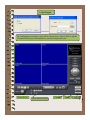
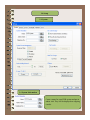
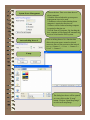
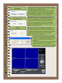
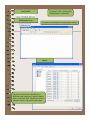
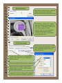
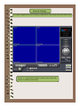
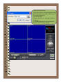
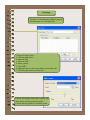
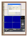
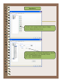
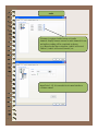
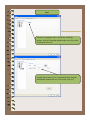
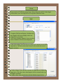
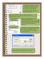
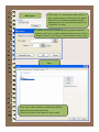
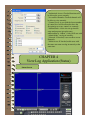
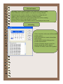
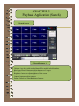
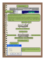
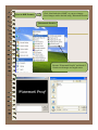
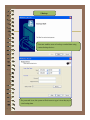
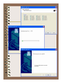
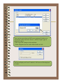
USER’S MANUAL
CHAPTER 1
Main System Application (Control)
1.1 Startup Screen
The above screen will appear as the system starts.
3.2 Login
The default values for User and Password are “admin” and “no password”. Click “OK”
to execute the Viewmax DVR system. To give “admin” a password and to create new
users, certain configurations in the Setup are required. Only “admin” and users with
appropriate authorization have access to the Setup menu.
1.2 Exit/Logout
By clicking the power button, a user will be asked as above. Select “Exit” to end the
Viewmax DVR system. Note that there’s a password required to exit.
3.3 Control Screen
Date/Time
User Mode
Model Name
Setup
Network
Adjust
PTZ Control
Camera Layout Panel
E-map
Power/Set Up
I-phone
Camera Selection Panel
Volume
Control
Light
Status
Search
1.4 Setup
1.4 System
1.4 System Information
Create a name for your DVR system and put in
admin. info. They will be displayed on outgoing
e-mails.
System Power Management
Auto-switching Interval
* Reserved time: Time set to shut down or
reboot computer
* Disable: selected when the system power
management is not to be used
* Shutdown: selected when shutting down
computer is required at the time set
* Reboot: selected when rebooting computer
is required at the time set
* Exit & Turn off Computer: By checking the
box, computer will be turned off automatically
as a user exits from the DVR system.
Auto-switching Interval is a function that
allows the green square around a selected
camera to move to the next one at the interval
set. e.g.) Camera 1 –> 10 sec. -> Camera 2 ->
10 sec. -> Camera 3….
E-map
The dialog box above will be opened
as a user clicks on the “E-map”
button. Click on “Open Map Image”
to select an E-map image.
The above is a sample picture. Drag your mouse to position Camera/Input/Output
and design your own E-map.
The E-map screen will appear as a user clicks on the E-map button positioned next to the
I-phone button.
White Camera: Not on Recording, Yellow Camera: On Recording
White Input/White Output: Not Activated, Yellow Input/Yellow Output: Activated
TV-OUT
TV-OUT is a function that sends a selected camera to a call monitor (external
analog monitor). Click on the “TV-OUT” button for setup.
* The models such as (240FPS/
240FPS) & (480FPS/240FPS)
support 2 TV-OUTs and the rest of
models support 1.
* Setup Options:
1. Same as Server Screen Mode
( For (480FPS/120FPS) only) TV-OUT Monitor displays what’s on
DVR server.
2. Manual Channel Selection – A user
manually selects a channel to be
displayed. Once the “Manual Channel
Selection” is selected, a user can also
change channels manually on the
Control screen by placing the mouse
on a camera picture and clicking right
mouse.
3. Auto Channel Switching – Selected
Cameras rotate to display at the
switching interval set.
* Switching Interval: The length of time
to stay at one camera
On-Screen Display
* Show Camera Names and Status: By checking it, camera names and status will be
displayed on camera pictures.
* Show Motion Detection Blocks: By checking it, green motion detection blocks will be
displayed on camera pictures as a user sets cameras under “M” (Setup/Schedule).
Text Inserter
Hard Disk Usage
I-Phone
Text Inserter is a function that allows DVRs to integrate
with POS machines. Simply install
“text_inserter_plugin_for_pos” on DVR Server, and
transactions that occur will be displayed on selected
camera pictures. It enables users to search data as well.
For more detailed installation, refer to Appendix 1.
Hard Disk Usage is to select data storage method.
If a user selects “Once”, data will be stored up to the
point where HDD reaches its maximum capacity.
If a user selects “Recycle”, data will be overwritten
from the point HDD reaches its maximum capacity
based on “First In First Out”.
I-Phone is also called “Two-Way Communication”.
Check the box, go to the Control Screen, and click on
the I-Phone button for audio communication with a user
on the other side of the world. For more detailed
I-Phone setup, refer to Appendix 2.
* Port No.: A port number for I-Phone use has
To be set up. Normally the default value is
good to use.
* Timeout: It indicates the maximum length of
connection trial. If there is no response
within the value set, the call will be cancelled.
* Version 3.4.0.0: version name
* Built 2004.4.14: built date
Version Info.
Maintenance Log
It is used to record and view maintenance history.
Device
The device sub-screen is divided into 5
different setup categories; Camera, Output,
Input, Audio and Alert. All devices in each
category can be set up on one same page.
Camera
Cameras will be enabled by checking
the boxes.
Different resolutions and recording
frame rates can be set up for different
cameras.
* Video Signal Type: Select either
NTSC or PAL.
* Auto Channel Scan: It automatically
identifies all the active video channels
with active cameras. Make sure to always
click and scan after a S/W version change.
* Default: It sets “Event Recording Frame”
and “Recording Frame” on default values.
[Camera]
Double-clicking on “Camera” will
Lead users for more individual
Camera setup.
Select recording picture quality.
* Pre-alarm (max. 20 sec.): Length of time to be recorded before event
* Post-alarm (max. 60 sec.): Length of time to be recorded after event
[Motion Detection]
MagicRadar is designed to have unlimited
motion detection zones and to have
different motion detection sensitivity levels.
Zone Settings: 1. Select “Set”, drag the
mouse to set motion detection zones and
click “OK”. As stated above, there are no
Limits in the number of zones.
2. Select “Clear” to clear certain areas
inside the motion detection zones.
3. Click on “Clear All” to clear all the
motion detection zones.
[PTZ Camera Setup]
If the selected camera for setup is a PTZ
camera, check the box and select a model
name. MagicRadar supports nearly 40
different protocols.
* Camera ID: Leave it as it is if only one PTZ
camera is used. Otherwise, give each camera
a different number.
Select the port that the PTZ camera is connected.
* Bit per Second: It is 9600 for most of PTZ
cameras. But a few can have different values.
Refer to camera manuals.
* Apply All: The same settings will be applied to
the rest of the cameras by clicking “Apply All”.
[Preset & Touring]
If a camera supports Preset and Touring, a right-mouse click will give users the below menu.
“Preset” is a function that enables a camera to move from one
position to another automatically.
* Steps to Set up Presets *
1. Move the camera to a desired position using
the PTZ Control on the main Control Screen.
2. Click the right mouse.
3. Name the preset.
4. Repeat the above for setting up as many as
256 presets.
5. Click the right mouse to run a preset and
click the “Auto” button to stop it.
[Touring]
“Touring” is a function that enables a group of
selected presets to work repeatedly.
* Steps to Set up a Tour *
1. Click the right mouse.
2. Name the tour.
3. Click on “Add”.
4. Select a preset.
5. Click “OK”.
6. Repeat the above to have more than 1 preset in the tour.
7. Click the right mouse to run the tour.
* Dwell: The length of time that a camera will
pause before moving to the next preset.
* Speed: Moving speed for a selected preset.
Output Device
Viewmax can be equipped with as many as 8 output
devices. Simply check boxes for use. In addition, outputs
can be manually activated from the main control screen
(Manual Alarm).
Double-click on “Output” for individual output setup.
* Name: Users can personally name output devices.
* Length of Activation: Users can determine how long a certain output device should be
activated in the case of an event (1-60 sec.).
* Length of Standby: It will determine how long a certain output device should be
deactivated until its reactivation (0-60 sec.).
* Apply All: The same settings will be applied to the rest of the output devices.
Input Device
Viewmax can be equipped with as many as 16 input
devices. Simply check boxes for use.
Each and every input can be tuned independently to function
as NO (Normally Open) or NC (Normally Closed).
NO: (+) & (-) detached normally
NC: (+) & (-) attached normally
Audio
Viewmax is equipped with as many as 8 audio
channels. Simply connect cameras to audio channels for use,
and audio recording will be completed as chosen.
(e.g.) Based on the above selections, Audio2 will record
Camera3, Audio3 will record Camera5, etc.
Input Gain (1-15): It is an audio level control similar to
a volume control.
Alert
Viewmax is equipped with 1 alert device inside the
system. Alert is a beep that sounds in the case of an event.
Check the box for use.
Length of Activation: Users can determine how long the
alert should sound in the case of an event (1-60 sec.).
Event
Event consists of 3 different groups; Input, Motion Detection and No Video Signal.
On this menu, users can assign devices to respond to different events.
Input
* Length of Full Screen Display: It indicates the
time length for full screen display in the case
of input device activation.
* Full Screen Display Channels: Users can select
camera channels to be full-screen displayed.
* Link to Recording: Users can selects as many as 16 cameras to record for
1 input device. The below shows that Camera1 will record in the case of
Input1 activation.
* Link to Output: Users can have as many as 8 output devices linked to 1
Input device. The above shows that Output1 will be activated in the case
Of Input1 activation.
* Link to Alert: Users can also have the alert linked to input devices.
Motion Detection
The same identical concepts and methods as “Input”
are applied to the “Motion Detection” setup.
No Video Signal
The same identical concepts and methods as “Input” are applied to the
“No Video Signal” setup. The above shows that Camera2 will take over
and record if there is a signal cut in Camera1.
Schedule
“Schedule” enables users to assign each camera, input or output its own activities.
Camera
Each camera can have different recording options; scheduled recording by
time & day and selective recording.
* R: Recording at all times
* M: Recording only on motion detection
* S: Recording only on sensor detection * H: Recording at all times and
higher frame recording on sensor/motion detection
Holiday recording schedule set at the bottom of
the “Schedule” table will be applied to
selected dates.
Input
Input
Network
Network Menu
DVR Server
* Supported Network:
1. TCP/IP - Connecting to a DVR Server from a Client using Lan or DSL
2. PSTN – Connecting to a DVR Server from a Client using a PSTN or ISDN modem
3. None – Not allowed to connect to a DVR Server remotely
* Port No.: The default port number is 9091.
* Timeout: The time length of trials to connect to a DVR Server from a Client
* Maximum Users: The maximum number of users that can be logged in remotely.
* Transmitted Video Quality: Users can select
video quality to be transmitted to a Client.
As a reminder, the higher video quality
gets, the slower network transmission
speed becomes. Therefore, it is often
recommended to select low video quality
when using “Narrowband”.
Router in Use: If there is a router in use, follow the steps below:
Check the box above. Æ Type in router’s IP address Æ Go to router’s setup
Æ Register DVR’s IP address.
Web Server
Central Station
* Port No.: Fixed HTTP Port No.
* Web Login Required: If the box is checked, login
is required as a user tries to connect to a DVR server
using the web browser. If the box is NOT checked,
a user will be automatically logged in as
“anonymous”.
“ Central Station” is a function that enables a Client
with a static IP to manage multi DVR sites. Check
the box and click on “Properties” for setup.
* Note: “cstation_server.exe” must be installed
on Central Station Server.
Type in the IP address of Central Station Server (Client with
Static IP) and click on “Reported Events” for more setup.
Users can choose events to report to a central
station server. Additionally, users can set
reporting time period.
E-mail
E-mail is a function that enables DVR to send out
e-mails when selected events occur. Check the box
and click on “Properties” for setup.
Make sure to put in the “RIGHT” IP
Address of SMTP Server. Then, click
on “Reported Events” for more setup.
The “Reported Events” menu is the
same as Central Station.
Dial Alarm
“Dial Alarm” is a function that enables DVR to
give a registered user a call and leave its number.
Then, the user will know something unusual is
happening at the site. Check the box and click on
“Properties” for setup.
A modem card must be installed inside the system to make this
function work. Type in a phone (mobile) number to report. Click on
“Reported Events” (same setup as Central Station) for more setup.
User
Users can be added, deleted or modified with different
authorized access and control levels.
There are no limits in the number of users created.
Choose one event from the list and click “OK”
for Event Search. The list will be updated by
clicking on the “Refresh” button.
[Object Search]
Object Search is only to search certain selected objects for a certain period of time.
Scan: Set the time period for object search
Motion Detection Zone: Select “Set” and mark areas for object search by dragging the
mouse. “Clear” is used when erasing certain areas inside motion detection zones.
Sensitivity: It means “Motion Detection Sensitivity”.
Clear All: It clears all the motion detection zones set.
* Authorized Access: Checked functions will
be allowed to access remotely.
* Accessible Channels: Checked channels will
be allow to view remotely.
* Control Level: A user with the lowest number
of control level will be allowed to have the
first priority to set up, control, etc remotely.
* Admin Mode: A user who can go into the
setup and program (given the same
authorization as “Admin”). Only ONE user with
“Admin Mode” can log in remotely.
* Network: If checked, a user can have access
Remotely.
* Multi-access: If checked, multi-users with
the same user name can log in remotely at the
same time.
CHAPTER 4
View Log Application (Status)
Status Screen
4 Screen Features
Recording Camera: It shows whether or not cameras are being recording.
Sensor Detection: It shows whether or not sensor are being activated.
Motion Detection: It shows whether or not motions are being detected.
Alarm: It shows whether or not alarms are being activated.
HDD Capacity: It shows how much capacity has been used for recording.
Event: It shows a list of events that have occurred.
Event Log: It is a function that enables users to view all the previous events.
4 Event Log
* Date: Any dates with events will be marked
in bold numbers.
* List: All events for a certain selected date
will be shown.
* Delete All: If clicked, all the previous
records will be deleted.
* Delete: If clicked, only the events for a
certain selected date will be deleted.
* Refresh: If clicked, events will be updated.
CHAPTER 5
Playback Application (Search)
5 Search Screen
5 Search Features 1
Calendar: Any dates with recorded data will be marked in bold numbers.
Blur/Sharp/Normal: Buttons to adjust sharpness of images
Zoom: Buttons to zoom in/out the screen
Brightness: buttons to adjust brightness of the screen
Contrast: buttons to adjust contrast
Default: Default for Zoom/Brightness/Contrast
5 Search Features 2
5 Playback
For playback, simply select a date, a screen mode (1, 4, 9, 16, etc.), time by one click on
the time bar and click the play button.
What different colors mean on the time bar: Blue - recorded data by sensor & motion
Detection; Purple - recorded data by 24-hour-recording; White – no recorded data in all
cameras; Gray – no recorded data for some cameras; Green – Blue + audio; Light Green
- Purple + audio
Stop
Play Backward * 2
Play
Play * 2
Play Backward
Event/Object Search
Move to the First Data
Move to the Last Data
Move 1 Frame Back
Move 1 Frame Forward
5 Event/Object Search
[Event Search]
Click the Event/Object Search button and select
“Event”.
Select one event from the list and click “OK”,
and the selected event will be displayed.
Click “Refresh” to update the list.
[Object Search]
Object Search is only to search certain selected objects for a certain period of time.
* Scan: Set the time period for object search.
* Motion Detection Zone: Select “Set”and mark areas by dragging the mouse. “Clear” is
used when erasing certain areas inside motion detection zones.
* Sensitivity: It means “Motion Detection Sensitivity”.
* Display Motion Detection: If checked, green motion detection blocks will be displayed.
* Clear All: Click “Clear All” to clear all the zones set.
* Start: Click “Start” for object search.
* Add Bookmark: Select a searched data from the list and click “Add Bookmark”, and it
will be stored in the Bookmark (Favorites).
5 Bookmark & Go To
Bookmark (Favorites): Added data from “
Object Search” are stored here.
Go To: It enables users to “Go To” the time set
automatically and search.
5 Save
AVI: For saving motion pictures and audio
BMP: For saving images. Watermarked images can
be saved.
JPEG: For saving regular still images. Quality is not
as good as BMP but less HDD is used.
[Save in AVI Format]
Click “Start” to start save and “Stop” to stop save.
Mute: Save video only (no audio)
High Speed: Save in high speed
[Save in BMP Format]
Click “Start”and select “BMP” as you save images.
Saved images can be checked using “Watermark Proofer”.
[Watermark Proofer]
[Save in JPEG Format]
Execute “Watermark Proofer” and check if
Certain saved images are forged or not.
[Save in JPEG Format]
Click “Start” and select “JPEG” as you save images.
5 Print
Click the “Print” button and follow the same printing procedure as
you would normally print out documents.
5 Backup
Viewmax enables users to back up recorded data using
various backup devices.
If a password is set, the system will ask users to type it in as they try to
view backup data.
CHAPTER 6
Remote Monitoring System (Client)
6 Program Execution
Double-click on the “Viewmax DVR Client” icon on the
desktop to execute the remote monitoring system.
Click “Add” to register DVR servers.
Note: Make sure to put the same Port No.
as DVR server.
Users can have more than one DVR server registered for their own
convenience. Select one from “Servers”, click on “Login”, type in
password to log in.
* Edit: Login info. changes can be made here.
* Delete: Registered servers can be deleted with one click.
Full Screen Display on Event: If checked, a full screen will be displayed
on events.