1
INSTRUCTION
MANUAT
FL-21o,o.z.
YAISUmus$tc0.,trD.
c P.o.Box 1500
ÍOKYO,JAPAN
YAESU
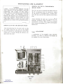
FL-2 IOOZ LINEAR AMPLIFIER
The FL-21002 is à high peribrmancelinear amplifier designedfor all Yaesu HF SSB
transceivef. This amplifier uses two 5728/T160 transnitting triodes in a ClassAB,
grounded-gridconfiguration. Operation on the 160 through l0 meter bands is provided.
C
Two quiet internal fans provide lorced air cooling lbr the final tubes. An intemal changeover circuit biases the tubes to cutoff duÍing receive operation, thereby eliminating
unnecessaryheat and diode noise generation. A unique safety ièature incorporated in the
design of the FL-21002 is a momentàry bias delay circuit, which protects the tank
circuitry from damageby delaying the activation of the final tubes until the T/R relay is
firmly seated.
An internàl relay connects the antenna directly through to the exciter dudng standby
operation, or wllen the amplifier is tumed off. A built-in SWR meter is also included, for
monjtoringof the feedlineSWR duringeitller ampliÍieror exciteronly operation.
The power supply lor the FL-21002 is built in. lt requiresno warÍnup time, and its
healy-duty construction provides excellent regulation.
We recommend
that you reàdthis manualin its entiretybeforecommencing
opeÍation.
Opemtion of the FL-21002 is extremelystraightforward,but improperadjustmentol
the controls and switchescould causereducedpower output or damageto the amplifier
With proper care, tlle FL-21002 will providenAny yean of reliable
components.
operation-
I
SPECIFICATIONS
Circuit type:
ClassAB, groundedg d
Tube complement:
2 x 5728f1160
Frcquency coveÍage:
160-10meteramateurbands
Coolingsystem:
Forcedair
Plateinput power:
1200 watts PEP SSB, 1000 wattsCW,400
wattsAM/FM/FSK
PowerÍequirements:
volts, 50160
AC 100/110/117/20012201234
Hz
Plat€voltage
2400VDC (no load)
CurÍentconsumption:
AC 100 117volts: 18amps
AC 200 234 volts: 9 amps
Driverequirements:
100 wattsPEPfor full output
I
j
I
Dimensions:
157(H)x 345(W)x 326(D)mm
Input impedance:
50 ohms,unbalanced
Weight:
Apprcximately20 kg
Output impedanc€:
50-75 ohms,unbalanced
f ,
subjectto changewithout notice or
Specifications
obligation.
3rd oÍdeÍ distortionpÍoducts:
-31 dB or better@ I Kw PEP
CAUTION
HIGH VOLTAGESARE PRESENTWITHIN
THE CABINET OF THIS APPARATUS.
HARMFUL OR FATAL ELECTRICSHOCK
WILL RESULT IF HIGH VOLTAGE
CIRCUITSARE TOUCHEDBY THE USER.
REFER ALL SERVICE WORK TO AN
EXPERIENCEDTECHNICIAN.
SAFETY INTERLOCK SWITCHESARE IN.
CLUDED IN THE FL-2IOOZTO DISCON.
NECT POWER IF THE TOP COVER IS
REMOVED. DO NOT ATTEMPT TO
DEFEAT THESESWITCHES,AND
ALWAYS
DISCONNECT THE ÀC LINE BEFORE
OPENINGTHE CABINET.
- 2 \
l
t.,-
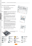
FRONT PANEL CONTROLSAND SWITCHES
(1) POWER
(7) PLATE
This is the main power on/oïi switch tbr the
amplifier-
This control adjuststhe tuning of the plate tank
capacitor-
(2) OPER/STBY
(8) SWR/AMMETER
This switch eppliesbies to the final tubesduring
standby (STBY) operation,cutting them off. The
relayis àlsodisengaged
ir1this condition.
a(3)
This meter displayseither the feedline SWR or
amplifier plate currcnt,dependingon lhe position
of the METERswitch.
METER
(9) PLATE VOLTAGE METER
lhe METERswitchselects
indicationon the SWR/
ammeterof plate current,relativeibrward power,
and relativereflectedpower.
The amplifier plate voltage is displayedon this
meter,in thousands
of volts.
(4) SWR SENS
This control setsthe SWRmetersensitivitylevel.
(5) LOADING
This control adjusts the tuning of the loading
capacrtor.
(6) BAND
Thisknobselccts
the blnd of operationioÍ the
amplifier,which mustbe the sameas that of the
transmitter.
3
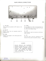
REAR APRON CONNECTIONS
I
I
(r)
RF OUT
This coaxial jack providesthe RF output to the
antenna.
(4) FUSE
For AC 100/110/1
17 volts,usea 20 ampfuse.For
AC 2OOl22Ol234
volts, use a l5 amp fuse.Do not
usea fuseofthe improperrating.
(2) RF IN
The RF input from the transceivershould be
connectedherc.
(s) ALC
This RCA jack is usedfor connectionto the tmnsceiverALC Line.
(3) GND
Connectthe amplifier to the station groundbus
at this point.
(6) RY
This RCA jack is used for connection to the
transceiver
relay(make-on-transmit)
contacts.
I
0r
{
I
I
I
CAUTION
NEVER OPERATE THIS EQUIPMENT
WITHOUT CONNECTINGIT TO À GOOD
EARTH GROUND. LIKEWISE, NEVER
OPERATE THE AMPLIFIER WITHOUT
HAVING AN ÀNTENNA OR DUMMY
LOAD CONNECÏED TO THE REAR
PANEL RF OUT JACK.
\
I
I
INSTALLATION
UNPACKING AND INSPECTION
Carefullyremovethe FL-21002 from its packing
crrton. and examine the unit ibr any signs of
visible damage.Check thc controls and switches
positiveaction-lf any damagehasbeen
1br nornlÍr1.
sustained,docrunentthe delnagecompletcly,and
notiÍy tlle sllippjng compàny at once. Seve the
packing cafton and foàm packing meterial foï
possibleuseat a lrter date-
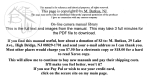
ma.keclon the rear apronof the ampliliermatches
your local supply voltage. Refer to the power
transforrner pdmary connection diagram when
changingvoliages.
It is essentialthat a fuse of the proper rating be
usedwith this equipment.For AC 100/110/117
volts,use only a 20 amp fuse.For AC 200/220/
234volts,useonly a 15ampfuse.
WARNING
INSTALLATION
PROCEDURE
In general.the tlr1plifierílould be sjtuatedin such
a way as to allow liee air circulation arcund flre
cabinet. Do not phce books, papers. or other
equipmcnt on top of the FL-2i002, and do not
o b . r | | . .I r l , ' r . e I - o * o [ 1 t Í t r \ J m r ' r e l n f J n o
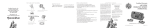
ReÍèr to the following page ibr intcrconnection
detailsofa typical installationusingthe FL fl00Z.
The ^LC input to the transceivershould be
connectedto thc FL-21002 ALC jack. The makeon-transmit contact ol the relay uscd ior T-R
switchingmust be connectedto thc FL-21002 RY
jack, with a common lead (to the outer contectof
RCAjack).
Use a short length of RG-s8A/U or RC8A/U coax
cable ibr the intcrconnectionbetweenthe transceiver ANT jack arld the FL,2l00Z RF IN jack.
For Ihe output lead frorn the FL-21002 RF
OUT jack, do not useUresmallRG-ssA/U type of
cable, as its power rating is insufficient ibr the
power levelproducedby the FL-21002.
The transceiverused to excite ihe FL-21002.
should be cepableofproducing 100 watts PEPSSB
outpui Ior full output iiom the amplifier.
PERMANENTDAMAGEWILL RESULTIF
IMPROPERAC SUPPLYVOLTAGE IS AP.
PLIED TO THIS EQUIPMENT.
OUR WAR
RANTY DOES NOT COVER DAMAGE
CAUSEI] BY
IMPROPER SUPPLY
VOLTAGË OR USE OF AN IMPROPER
FUSE.
If at all possible.
the FL-21002shouldbc operated
iiom an independent
220-voltAC line_The line
should be fused for 10 amperes,
and no other
equipment
shouldbe run off the samecircuit.lf a
I 17-voltcircuitis a1lthat is àvàilable,
it shouldbe
fused ibr 20 amperes,and circuit conductors
shouldbe no smallerthan#10 AWG.UNDERNO
CIRCUMSTANCES
should the FL-21002 be
operatedfrom a I I ?-volt houselighting circuit, as
the cifcuit condLrctors
may not be largeenoughto
c.lrrythiscurent loadANTENNA REQUIREMENTS
The FL-21002has beendesigned
for usewith an
presenting
antenna
a 50 to ?5-ohmrcsistive
loadto
the RF OUTjack. Wren usingàn antenna
presenting an impedancewhich is far from this figure,
use an antenna natching network in oroer ro
bring the antennasystemimpedancewithin the
operatingrangeof this ampliÍler.
POWER CONNECTIONS
GROUND
The FL-21002 includesa builFin power supply
capableof operationfrom AC 100/ll0/ll71200/
220/234 volts. 50/60 Hz. Betbre connectingthe
amplilier power cord to the AC supply meins,be
absolutely certain that the voltage specification
This ainplifier shouldbe connectedto a goodearth
ground,usinga hea\.ry,
braidedcablenot more than
10 1èetlong for connectionto the stationground
bus. The connectionofthe groundcableshouldbe
madeto the tearapronGND terminal_
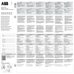
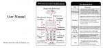
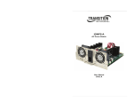
INTERCONNECTIONS
FL.21002
MON
I
9
FT 901/902
NOTE
a
a
3
3
1
1
1
3
3
3
r Jumpê6 m!si be in$al ed as indl€led. Thê FL 21002ls à non-OsK
amplller,and may bê dàmàqêd by attempting OSK operarlon.
shielded €be
with rhe bráid cónnêc1èdto common/sround.
RY plus may bejumpered
Jz*
t-
ltotl
ll *.t
.l@v
o
ltTv
t
tr
t'lr t
00v
CRAY
V IOLET
BLUE
GREEN
YELLOW
ORANGE
roov
G
o
@
RÊD
BROWN
t l
t l
AC
234V
l r
AC
??ov
zow
7V
llo V
|OOV
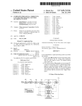
POWERTRANSFORMERPR1MARY CONNECTIONS
6
t
OPERATION
BF]FORECO\4MENC]NGOPERATION, CON.
'fHÊ
FIRM THAT
POWI]R TRANSFORMER
PRIMARY lIAS BEEN CORRECTLYWIRED
FOR YOUR LOCAL,{C SUPPLYVOLTAGE,
AND CONFIRM ]'HAT A FUSE OF THE
PROPERRAI'INC HAS BEEN INSTALLED.BE
CERTAIN TIIAT AN ANTENNA IS CON
NECTEDTO TIIE RF OUT JACK.
'Ihc
exciternray be tunedup with the amplilicr
on or off. If you tune up the exciterwith the
ampliiierturnedon. serrheOPER/STBY
to STBY
duringexcitertuning.
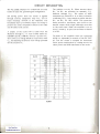
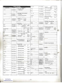
Presetthe FL-21002 controlsand switchesas
tbllows:
POWERswitch.....OFF
O P E R / S T BsYw i t c h . S I B Y
MbTERswitch.....lP
B A N Ds w i t c h . . .. . . . D e s i r cbdr n d
PLATEcontrol . . . . . To the positionshowntn
Table L
LOAD control
. . Fully counierclockwiseto
number0-
Tunr the FL-21002 POWER swiich ON. and
recheck the exciier tu|ing with the OPER/STBY
switch still sci to STBY. Now rotate the exciter
drive control fully counterclockwise(mlnlmuÍr
drive level).
Set the OPI-R/STBYswitch to OPER.
Close the excite. PTT switch, end slowly advance
thc drive control ol-the exciter until a readingof
0.2 emps is obtained on the FL-21002 plaie
meter. Tune the fL-21 002 PLATE corrtrr,rl
ibr a
dip (rninimun metcr Íeading)in the plaie current
indication or thc lneier. Retu|n the exciter to
standby(release
the P'I I' switch).
Placcthe MËTER switch in the FWD position(to
read rclative Íbrward power). Agah apply drive
froln the exciter. arrcl advancethe SWR SENS
control for a rcading of rpproximately I/a scale.
Now advancc thc LOAD oontrol in sniill increments, e ch time tuning the PLATE control lot a
maximum forward power reading.^djLrstthe SENS
control, as necessary.to preventoff-scaledeflection of the ibrward power mcter.
DO NOT EXCEED ] O SECONDSOF KEY.DOWN
TIN'IE DURING TUNING, SO AS NOT TO
DAMAGE THE BXCITER OF AMPLI]iIER
FINAL TUBES,
Peak power should occur at a platc current (lP)
readingof appÍoximately 0.5 amperes.Approxi
Inàte settingsof the I.L-:1002 LOAD control
for màximuIr1output into a 50 ohm load are shown
i n f a b l el .
When tuning, be certainto start Àt r very low drive
level, nd keep the plate currcntdipped. Likewise,
do not begin tuning with the LOAD control
advanccdbeyond the 0 point. The corÍect tcchnique is to increasethe excite. drive only aftcÍ an
initial dip is obtained ir1 the plate cLrrfent.With
propef care taken in tuning,your FL-ll00Z will
I ' r u ! r d en . . n y y e r r . o f . r o r r b l er ' e eo i r e r J l r o. ,
The amplificr is now iuned Íbr SSB and CW operation. For SSB opetution, the exciter should bc
adjusted so thrt rhe FL-21002 piate cutrent
indicrtes between 0.2 and 0.3 amperes under
normal voice operating conditions. Ilecàusethe
neter cannot follow the current llow correspondjng to lhe spcechsignal,the actual peak current
value is approximatclytwice the value shown on
For AM operation, tune up the FL-21002 as
de cribeJ ibove. Now r.l u.r r're "\circr caríicl
levelfor a plate cu ent indicationo[ 0.2 ampswith
u.modulated carrier-If an exciter capableol FM
or FSK operationis usedwith the F'L-ll00Z . do
not exceedthe fatingsstipulatedfbr AM operation.
For CW operation,set the dÍive levelof the excrter
for a power inpllt of I kilowatt (e.g-0.5 amps at
2000 volts plate currentunder load).
To measurethe SWR at the antennejack, set the
meter switch to FWD (Forward). arrd apply RF
power. Adjust the SWR SENS control for a full
scalc dcflection of the SWR meter. Now set the
METER switch to REF (Reflected).The SWRmÀy
be reeddirectly from the upperscaleof the meter.
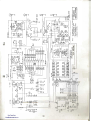
CIRCUITDESCRIPTION
The FL-21002employstwo 5728/T160zerobias
triodesin classAB, grounded-gidconfiguration.
RF d ving power from the exciter is applied
through antenna changeoverrelay RL, and an
input matching network to the filaments. The
broadbandinput pi networksrequircno tuning to
presentthe correctimpedancematch to the tubes
and 50 ohmsto the exciter.
A sample of the exciter RF is taken from the
filamentsthrough Cr! to ALC rectifier diodesDr
(151007)andD, (10D10).Trimmercapacitor
TCr
then servesas a voltagedividerin conjunctionwith
Cr,, for adjustingthe levelof ALC voltageprovided
for the exciterat J3.
BAND
160
80
FREQ
(MrL)
The grid bias is set by Ra. When antennarclays
RL, and RL, are activated(to transmit), Cao6
dischalgesthrough R3oa. The values of these
componentsare selectedso as to delay activation
of bias relay RLor long enougl to ensurethat the
RLr and RL, are fully closed-This protective
featurc preventsa momentaryopen circuit ai the
ampliÍieroutput which might otherwiseoccurdue
to rclay tmvel time. while the amplifier is set to
standby,switchSa is openand the tubesare biased
to cut-off.
The plates of the amplifier tubes are connected
through an adjustablepi network of the RF OUT
jack, and the output is sampledfor dircctional
relativepowermeasurement
by a bridgecircuit, for
power
rclative
and SWRindicationson the meteÍ.
PALTE
1.8
2.0
3.5
4.0
'7.O
40
30
20
l7
15
t2
l0
7.5
10.0
10.5
14.0
I
9
l
6
3.5
5
5
5.5
'7
14.5
'1.5
18.0
18.5
21.O
5.5
6
8
)t.5
LOADING
t
7
I
3.5
1.5
2.5
2
2.5
3
3.5
).
2.5
4
24.5
25.O
28.0
29.7
Table I
- 8
7
'7.5
9
l0
3
3.5
4.5
)
MAINTENANCE
AND ALIGNMENT
REMOVAL OF THE PA COMPARTMENT
SHIËLD COVER
WÀRNING
LETHAL VOLTAGESARE PRESÊNTWITHIN
THE CABINETOF THIS EQUIPMENT.
BEFORE
REMOVINGTHE COVERS OF THIS AMPLI,
FIËR, UNPLUGTHE POWERCORNFROMTHE
AC SUPPLYLINE. USE EXTREMECAUTION
WHENEVERMAKINGANY ADJUSTMENTS
INSIDE THE CABINET.NEVËR WORK ON THIS
ÀMPLlFltsRWHILE ALONE: YOU MAY NEED
SOMEONE
TO TURN OFF THE POWERQUICKLY.
Oncethe top coveris removed,the shieldcoverfor
the PA cornpaÍment may be removedby taking
olf the screwsof the shieldcover.A safetyinter_
lock will short out the filter capacitonwhen this is
Always discharyethe plate cap to g.ounalwith an
insulated scrcwddverwhen working on the pA
comparlmentcircuitry. Wait at least ten minutes
after tuming the amplifier off beforeremovingthe
shieldcover.
R€MOVAL OF TOP ÀND BOTTOM COVERS
After disconnectilgthe AC poweÍ cabiefrcm the
AC supply mains,the top cover oí the amplifier
may be removedby removingthe I screws.Then
removethe 12 screwsaffixing the bottom cover,
and rcmovethe cover.
TUBE REPLACEMENT
If replacementof ihe amplifier tubes becomes
necessary,use tubes of identical manufactureas
the originals.Seeyour Yaesudealer.
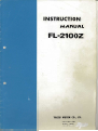
Cr
TOP VIEW
Fig. I
I
Betore touching the final tubes be sure to discharge
thc plate caps of both tubes by shorting theDr to
groundwith an insulatedscrcwdriveÍ
TROUBLESHOOTING
Should trouble arise which cannot be cured by
that the amplwe recommend
tube substitution,
her be retumed to the dealer from whom yolr
purchasedit for seÍicing. If this is impossible'
writeto the Yaesuagentin your countÍy,including
as many details of the pïoblem às possiblc ln
counlrieswhercYaesuis not curlently rcpresenled,
yolr may write directly to the 1àctory: Yaesu
Box 1500,Tokvo' JapanMusenCo., Ltd-, C.P.O.
We will then adviseyou as io the best coune ()1
Once tube replacenentis completed,replacethe
shielcl cover and the cabinet before ptugging the
AC cord into the AC supply outlet. NeveÍ apply
AC power with the shield cover removed
I]IAS ADJUSTMENT
Set the OPF-R/STBYswitch to OPER Close thc
exciter PTT switch (SSB mode), and note the
amplilier tP readingwith no nodulation (no RF
input to the amplifier). The meter IP in.lication
should be 0.09 amperes;if it is not, then adjust_
ment of Ihe bias setting is rcquirecl
action.
or
shouldtroubleshootiltg
Underno circumstances
seÍvicingof this equipmentbe attenptedby any
with high_
experienced
one otherthan à teclmician
Removethe bottom cover of the amplifier' Tum
on the .rmplifier, end adjust Ra for a reading ol'
exactly 0.09 anps of idling cunent Use extrcme
caLrtion.as high voltage is prcsent
TUBE REPLACEMENT
Wàit at leêst l0 minutesalter hrvingtumed off
the powercablefrom
the FL-2t002. Disconnect
the cabinetof
remove
the AC supplyoutlet,and
the amplifier. Removethe shield càseol the PA
compàÍtrnentto gainaccessto the final tubes'
PB-1135
P B ' ]9
-2056A
"-f
a .
.J
dt
0_
'
IJ
.J
BOTTOM VIEW
Fig. 2
l0
EEry
v1.2
có090005
c31,39
P309004?
s5000018
c35
K24390003
c3l 34
K24356501
c3,30
K24356102
c38
K40140227
vcl
I<90000032 YP-120-22 l20DF
(90000031 530P\lL
5]0Dh1
5?28/T160
V A C U U MT U B E S O C K E T
v st , 2
c36
K r 3 1 7 9 0 0 9 Ceianic
50wv 0.047rr!
tDDu0F4?3(50V1
K24390002
?KV
lofuF
DescriDtion
G2010070
c2090002
-
DA2l]4UX
PLAT! CÁP HV.]l]|]I
Silicon
3Kv
500PI'
1000pF
Ele.rrólytic 2swv
t25RL220)
DIOOE
DI
D2
3,t5pF
220rF
10D10
VARIABLE CAPÀCITOA
vc2
Rlt
R5
Rt0
J 0 i 2 4 5 5 1 2 C a r b o nf i l n l / 4 W I J 5 . l k o
" RD1P821 820r,
J0110582r "
!\0216472
v2wc( 4.7kO
Rt2
R 3 ( w i l hM 1 )
R2
22A
33Í|
TC2
30í}
0.21'|
3MOJ
L2
J21355330
i20l0bl30
M e r a l [ cf i l m l W
]lÍ)
J20116473
J 3 1 4 0 ó 3 0 0 wire wonnd variableIoW
RWH-Iocl
Jt2009006
À Á e r es rh u n l
J 3 2 0 0 9 0 0 5 RH2HVD
2W
T R I M M E AC A ' A C I Í O B
TCl
LI
L3
L4,5(R6,9)
L6
K91000016 ECV'12w50x32
K91000001 TSN-150C30P
50DF
30nF
Lr02a661C
L1020659
L1020661
L102066411
L0020758A
L7
L8
J 6 0 8 0 0 0 6 8 EVH80Á520854
L1020064
50koB
PII
cll
K 3 0 2 7 9 0 0 5 DippedMica 500WV 3pF
c24,25
K30279t2l
c21.
K30279021
(DMl5D030D5)
K30219029
c28
'
(DM15D5l0K5)
(DM15D101K5)
"
íDMl5Dt2t(5J
K302?9031
"
5lpF
Ml(wilh R3)
t 0 0 p F M2
120pF
l50pF
(DM15Dl5lK5)
c21,26
c21
c20
cl9
íDM15D221Ks)
K10279017
(DMl5D271K5)
K302?9085
(DM19D33tj(5)
"
K30219\13
K30279035
ct8
cl,2
"
íDMl9D222K5)
K302?90ó0
(DM19D242K5)
Kt2329001 Ceramic
1.4(V
K30279059
4 w 5 2 2 1H P 2
s1.4
wD922l
220pF
270pF
330pF
s2
s7
FANT.2
M2190001
56
2200pF
aM2ltl
N 0 1 9 0 0 6 0 ESR-El43R-202íMetei)
R0011670A
N0050051
N0050052
680pF
(DM19D68lKs)
cl6,1?
RLI
RL2
240OpÊ
0.0l,rF
(ECK.DÁLIO3PE)
c8,9
K12279002
500wv 0.01,rF
(ECK
D2HlO3PE]
(00159002
"
3Kv
(cc45sL3F22l(Y)
220pF
PLI-2
K0252-6-814V 40nÁ
DCt2V
F1
o0000008
P!-2056A
F00020s6a
c020560A
IUSE
FHI
Jl 2
J3.,1
P1090028
P1090r33
L9190001
L910035
T7600001
T9000382
T9000680
T9000584
Q6000041
PB-l135
HOLOER
sN2050
or00Ë
D201.202
G 2 0 9 0 It 3
R202
R201
R203.204
tot2454t0
c201
K30t164',11 Dippednica
Schottkvbarrier
MBR.06B
sTR-o1-3
REStSfOR
Carhonliln
l/2WT., 47o
J00245102
"
J00245104
-
l00ko
Ri3x3x1
c202,203
50WV
470pF
(zl8D4?l(05)
K 1 3 1 7 9 0 0 9 Ceramic
0.04?r1F
TC20l
] ( 9 1 0 0 0 0 1 9 E C v - ! Z W1 0 x 4 0
L20t
L0020301a
3 wÍe,3 pronsUt plue
3 wire, 3 pronÊADstraljanDluc
I wire, 2 pronp!U Dlu!
TRIMMER CAPACIfOR
l0pF
ML-33918P(H)
F0001135
c011350A
PB-1903
F0001903
c019030A
OIODE
Dl01 I l0
c2090002
Silicon
10D10
D301,302,304.30
5
c2090001
D303
c2090002
DIODE
Silicon
"
10D1
10D10
RESISTOB
Rl0t-110
1102764',14
v2w cK 470ko
PB-1112Á
F000tll2Á
c0ll l20A
170!16)24
t02245t02
Jt0276r5l
R303
,t10216413
t10216224
R306
Rl05
R301,302
c305
ÀËstsToF
R1l1 113(A)
R lr 4 1 1 6 1 8 )
RESISTOR
R30?
R304
MelruicÍilm 2w
220ko c306
c301.304
Cdhonlilm
1/4WSJ lko
v2w cK 150Í,
"
J2030ó330 Metauic6lm lw
J20336560
- 4?ko
_ 220kÍl"
33ír
(40100337 Eleclrolytic lowv
K40149003
í10RL310)
"
25WV
(25RE100)
K40149002
330rF
100pF
47OltF
(25RE4?0)
c10l 103(A)
ct04-106(B)
c302,303
K43270004
Electrolytic 500WV 100ÈF
(ECE-M2HRlOlER]
x401804?ó
"
(63RL,17)
63\w
47tF
RL3O1
M1190002
PB-2164
F0002164
c021640
c406
c404,405
( 3 0 2 7 9 0 3 1 DippedMica 500Wv r50pF
(DMl50Dr5lK5)
"
360pF
K30279040
c403
K30219044
FBR2lIAD{]l2M
(DM19D36lK5)
c402
c40i
(DMt9D511(5)
K30279049
(DM19D821](5)
K30279055
(DM19D152K5)
510pF
820PF
1500pF
INDUCÍOR
L401
L402
L403
L404
L405
1406
L407,409
L408
L0020849
L0020613
L0020848
L002061?
L002084?
L0010670
L0020621
L0020622
t0090019
P0090018
Q0000009
Q0000008
Fuse20A
-
r5A
O00 ll?\l
(200 234v)
3
I
B
:àPt:
*Q9Ët
"$s3sï
(
1
"i---l"I--{i ",;glli ,' ,;t"
1''']Ëfl,fufr$rË
l.--l--l'-l
9
,)
gl
:P
-el
el
9p
,31
-l
{
-
'"1
:
r5
-91
8
ÈL
.9
t
ia
!h
;
lf,