1
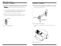
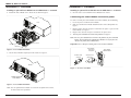
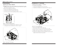
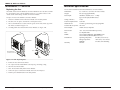
IONPS-A
AC Power Module
User Manual
33423.A
IONPS-A, AC Power Module
Table of contents
Cautions and Warnings . . . . . . . . . . . . . . . . . . . . . . . . . . . . . . . . .3
Definitions . . . . . . . . . . . . . . . . . . . . . . . . . . . . . . . . . . . . . . . . . . . . . .3
Cautions and warnings in this manual . . . . . . . . . . . . . . . . . . . . . . . . .3
Description . . . . . . . . . . . . . . . . . . . . . . . . . . . . . . . . . . . . . . . . . . .4
Power Module component identification . . . . . . . . . . . . . . . . . . . . . . .4
Notices . . . . . . . . . . . . . . . . . . . . . . . . . . . . . . . . . . . . . . . . . . . . . . . . .5
Installation . . . . . . . . . . . . . . . . . . . . . . . . . . . . . . . . . . . . . . . . . . .5
Power Module redundancy . . . . . . . . . . . . . . . . . . . . . . . . . . . . . . . . .5
Installing an optional Power Module into the ION chassis . . . . . . . . .6
Connecting external power . . . . . . . . . . . . . . . . . . . . . . . . . . . . . . . . .9
Maintenance . . . . . . . . . . . . . . . . . . . . . . . . . . . . . . . . . . . . . . . . . .10
Replacing the Power Module . . . . . . . . . . . . . . . . . . . . . . . . . . . . . . . .10
Replacing the fuse . . . . . . . . . . . . . . . . . . . . . . . . . . . . . . . . . . . . . . . .12
Technical Specification . . . . . . . . . . . . . . . . . . . . . . . . . . . . . . . . .13
Troubleshooting . . . . . . . . . . . . . . . . . . . . . . . . . . . . . . . . . . . . . . .14
Contact Us . . . . . . . . . . . . . . . . . . . . . . . . . . . . . . . . . . . . . . . . . . .15
Compliance Information . . . . . . . . . . . . . . . . . . . . . . . . . . . . . . . .16
Cautions and Warnings
Definitions
Cautions indicate potential damage to equipment.
Warnings indicate a potential hazard or injury to people.
Cautions and warnings in this manual
Cautions and warnings are explained here and placed throughout this manual where
appropriate.
CAUTION: While installing or servicing the Power Module, wear a grounding
device and observe all electrostatic discharge precautions. Failure to observe this
caution could result in damage or failure of the Power Module.
WARNING: Do not connect the Power Module to an external power source before
installing it into the chassis. Failure to observe this warning could result in an
electrical shock, even death.
WARNING: A readily accessible, suitable National Electrical Code (NEC) or
local electrical code approved disconnect device and branch-circuit protector must
be part of the building's installed wiring to accommodate permanently connected
equipment. Failure to observe this warning could result in an electric shock, even
death.
WARNING: Turn the Power Module and external power source OFF and ensure
that the Power Module is disconnected from the external power source before
performing any maintenance. Failure to observe this warning could result in an
electrical shock, even death.
2
Tech Support: 1-800-260-1312 – International: 00-1-952-941-7600 – (24 hours)
[email protected] – Click the “Transition Now” link for a live Web chat.
3
IONPS-A, AC Power Module
Description
Description — continued
Transition Networks’ IONPS-A, AC Power Module can deliver power or provide
optional, redundant AC power to an ION219-A chassis. See the ION219-A chassis
manual #33421. You can download the manual @ www.transition.com, then click on
Product/Product Finder.
Power Module component identification
Notices
•
The IONPS-A, AC Power Module must be installed by qualified technical
personnel only. Transition networks assumes no responsibility for the improper
installation, set up, or use of the IONPS-A, AC Power Module.
•
The information in this user’s guide is subject to change. For the most up-to-date
information, see the user’s guide on-line to download the current version of the
manual at www.transition.com under Products.
See Figure 1:
1
Fans (two fans exhaust warm air from the IONPS-A, AC Power Module)
2
Power LED (ON green when powered up)
3
ON/OFF switch, when in the ON position power is supplied to the ION chassis
IMPORTANT
4
Fuse (inline AC)
•
All installation and service must be performed by qualified personnel only.
5
Handle
•
6
AC Power Receptacle for an AC power plug
Read, understand, and follow all CAUTION and WARNING notices, instructions
marked on the product, including in this manual.
7
Dry Contact Relay (optional)
Note: The IONPS-A, AC Power Module has instant failover capability.
Installation
The IONPS-A, AC Power Module can replace an existing IONPS-A, AC Power
Module or it can be installed as the redundant Power Module in an AC powered
ION219-A chassis.
CAUTION: While installing or servicing the Power Module, wear a grounding
device and observe all electrostatic discharge precautions. Failure to observe this
caution could result in damage or failure of the Power Module.
Power module redundancy
The IONPS-A, AC Power Module includes Instant Fail-Over (IFO) circuitry that
provides the capability for the primary Power Module to power the chassis backplane
while the auxiliary Power Module is in ‘hot’ standby mode. If the IFO circuitry detects
the loss of primary power, the auxiliary Power Module instantly provides power to the
chassis backplane. When primary power is restored, the IFO circuitry places the
auxiliary Power Module in ‘hot’ standby mode. The chassis primary Power Module is
located in the left slot of the chassis as viewed from the rear. The chassis auxiliary
Power Module is located in the right slot of the chassis as viewed from the rear. A
single Power Module placed in either location can power the chassis backplane.
1
2
3
Note: The IONPS-A, AC Power Modules DO NOT load share.
4
5
6
7
1
Figure 1: Power Module Components
4
Tech Support: 1-800-260-1312 – International: 00-1-952-941-7600 – (24 hours)
[email protected] – Click the “Transition Now” link for a live Web chat.
5
IONPS-A, AC Power Module
Installation — Continued
Installation — Continued
Installing an optional Power Module into the ION chassis
Installing an optional Power Module into the ION chassis — continued
WARNING: Do not connect the Power Module to an external power source before
installing it into the chassis. Failure to observe this warning could result in an
electrical shock.
2. If necessary, remove the grounding hardware from the chassis before installing or
removing the Power Module. See Figure 3.
Chassis
Grounding
Posts
Note: The Power Module is hot swappable (i.e., swapped while the chassis is in
operation) provided the ON/OFF switch of the Power Module is in the OFF
position, and it has been disconnected from its external power source.
To install the Power Module in the ION chassis, do the following:
Note: The procedure is the same for installing the Power Module into either slot.
1. Push the Power Module ON/OFF switch to the OFF position. See Figure 2.
Kepsnuts
(provided)
Power Module
Switch OFF Position
Compression Lugs
(Not Provided )
Figure 3: Chassis Grounding Hardware
Figure 2: Power ON/OFF Switch
3. Remove the slot cover from the right chassis slot and keep the two screws. See
Figure 4.
S lo
tC
ov
er
Screws
Figure 4: Chassis Slot Cover
6
Tech Support: 1-800-260-1312 – International: 00-1-952-941-7600 – (24 hours)
[email protected] – Click the “Transition Now” link for a live Web chat.
7
IONPS-A, AC Power Module
Installation — Continued
Installation — Continued
Installing an optional Power Module into the ION chassis — continued
Installing an optional Power Module into the ION chassis — continued
4. Position the Power Module at the chassis slot, as shown in Figure 5.
6. Insert the two screws to mount the Power Module to the chassis.
Connecting the Power Module to external power
To connect external power to the IONPS-A, AC Power Module, do the following:
Chassis
1. Locate the power cord for the Power Module.
2. Make sure that the Power Module ON/OFF switch is in the OFF position. See
Figure 7.
3. Plug the female end of the AC power cord into the AC power receptacle on the
Power Module. See Figure 7.
4. Plug the male end of the AC power cord into the AC power source.
5. Turn the power ON/OFF switch to the ON position. See Figure 7.
Note: Once the power ON/OFF switch is in the ON position, the power ON LED
will lite. This means that the optional Power Module is ready to power the
chassis if the primary Power Module fails.
Power Module
Important: There is NO power sharing between the two Power Modules.
Mounting Screws
Power Module
Power Cord
Receptacle
Figure 5: Power Module Installation
Power Module
ON/OFF Switch
5. Side the Power Module completely into the chassis. See Figure 6.
AC Power Cord
(male end)
AC Power Cord
(female end)
Chassis
Figure 7: AC Power Cord Ends
Installed Optional
Power Module
Figure 6: Power Module Installation
Note: Once the optional Power Module is seated to the backplane of the chassis,
the fans will become operational.
8
Tech Support: 1-800-260-1312 – International: 00-1-952-941-7600 – (24 hours)
[email protected] – Click the “Transition Now” link for a live Web chat.
9
IONPS-A, AC Power Module
Maintenance — Continued
Maintenance
Installing the Power Module — continued
Replacing the Power Module
WARNING: Do not connect the Power Module to the external power source before
installing it into the chassis. Failure to observe this caution could result in equipment
damage and/or personal injury or death.
6. Locate the new Power Module.
7. Push the power ON/OFF switch to the OFF position.
8. Position the Power Module at the chassis slot, as shown in Figure 10.
To replace the Power Module, do the following:
1. Turn the power ON/OFF switch to the OFF position.
2. Disconnect the AC power cord from the power source.
3. In necessary, remove the chassis grounding assembly. See Figure 8.
Chassis
Chassis
Frame
Nuts & Washers
(Not Provided)
Guide
Grounding Terminal
Lug (Not Provided)
Mounting Screws
Figure 8: Chassis Grounding Hardware
Power
Module
4. Remove the two screws securing the Power Module to the chassis.
5. Carefully pull the Power Module from the chassis. See Figure 9.
Figure 10: Power ON/OFF Switch
9. Slide the Power Module complete into the slot.
11. Insert the two screws to secure the Power Module to the chassis.
Chassis
12. Plug the AC power cord into the AC receptacle on the Power Module.
13. Plug the other end of the cord into an external AC power source.
14. Push the power ON/OFF switch to the ON position. The power ON LED
should be lit and the fans will be operational.
Mounting Screws
Power Module
Figure 9: Removing Power Module
10
Tech Support: 1-800-260-1312 – International: 00-1-952-941-7600 – (24 hours)
[email protected] – Click the “Transition Now” link for a live Web chat.
11
IONPS-A, AC Power Module
Maintenance — Continued
Technical Specification
Replacing the fuse
For use with Transition Networks Model IONPS-A, AC Power Module.
CAUTION: Ensure that the IONPS-A, AC Power Module has been disconnected from
the external power source and the ON/OFF switch is at “0.” Failure to observe this
caution could result in damage or failure of the Power Module.
Dimensions:
8.3" x 8.4" x 2.7" (211 mm x 211 mm x 69 mm)
Weight:
4 lb. (6.35 kg) approximately
Power Input:
100-240 V, 47/63Hz, 2.35 – 1.1 Amp
(typical with a fully-loaded chassis)
1. Ensure the ON/OFF switch on the Power Module is in the OFF position.
Voltage Tolerance:
± 10%
2. Disconnect the AC power cord from the external power source.
Low-Line Input Current:
3.5A max.
3. Insert a small flat blade screwdriver into the groove on the front, inside edge of the
fuse holder, as shown in Figure 11A.
Inrush Current:
13A max. ( peak starting current) @ high line
4. Carefully pull the fuse holder from the Power Module. See Figure 11B.
Power Output:
To replace the fuse in the IONPS-A, AC Power Module:
(A )
(B )
Power ON/OFF
Switch
Place Small Flathead
Screw Driver Here
Transient Recovery Time: 1ms max.
12VDC at 16.67 Amp max.
Power Factor:
>0.6 – 0.95, 10 to 100% load respectively
Fuse:
6.3 Amp/250 Volts
MTBF:
Greater than 25,000 hours (MIL-HDBK-217F)
Greater than 68,750 hours (Bellcore7 V5.0)
Environment:
Operating temperature:
Storage temperature:
Humidity:
Lifetime
Warranty:
0 to 50°C (32 to 122°F )
-25 to 70°C (-13 to 158°F)
5 to 90%, non condensing
Fuse
Fuse
Holder
Figures 11 A & B: Replacing Fuse
4. Remove the fuse from the fuse holder.
5. The replacement fuse MUST BE the same amperage and voltage rating.
6. Insert the fuse into the holder.
7. Slide the fuse holder fully into the Power Module.
8. Connect the power cord to Power Module and to the external power.
9. Push the power ON/OFF switch to the ON position.
12
Tech Support: 1-800-260-1312 – International: 00-1-952-941-7600 – (24 hours)
[email protected] – Click the “Transition Now” link for a live Web chat.
13
IONPS-A, AC Power Module
Troubleshooting
If the Power Module fails, isolate and correct the failure by determining the answers to
the following questions and then taking the indicated action:
1.
2.
Is the Power LED on the IONPS-A, AC Power Module illuminated?
NO
•
Is the Power Module inserted properly into the chassis?
•
Is the Power Module properly connected to the external power source?
•
Does the external power source provide power?
•
Contact Technical Support: US/Canada: 1-800-260-1312, International:
00-1-952-941-7600.
YES
•
Proceed to step 2.
Is the fuse on the IONPS-A, AC Power Module intact?
NO
•
CAUTION: See the “Replace the Fuse” section for the proper method
for replacing the fuse to the Power Module.
•
Contact Technical Support: US/Canada: 1-800-260-1312, International:
00-1-952-941-7600.
YES
•
Contact Technical Support: US/Canada: 1-800-260-1312, International:
00-1-952-941-7600.
Contact Us
Technical Support
Technical support is available 24 hours a day.
US and Canada:
1-800-260-1312
International:
00-1-952-941-7600
Transition Now
Chat live via the Web with Transition Networks Technical Support.
Log onto www.transition.com and click the Transition Now link.
Web-Based Seminars
Transition Networks provides seminars via live web-based training.
Log onto www.transition.com and click the Learning Center link.
E-Mail
Ask a question anytime by sending an e-mail to our technical support staff.
[email protected]
Address
Transition Networks, 10900 Red Circle Drive, Minnetonka, MN 55343, U.S.A.
telephone: 952-941-7600; toll free: 800-526-9267; fax: 952-941-2322
Declaration of Conformity
Name of Mfg:
Model:
Transition Networks
10900 Red Circle Drive, Minnetoka, MN 55343 U.S.A.
IONPS-A, AC Power Module 120/240 VAC
Purpose: To declare that the IONPS-A, AC Power Module to which this declaration
refers is in compliance with the following directive(s) and standard(s):
EMC Directive 2004/108/EC; EN 55022:2006+A1:2007 Class A;
EN55024:1998+A1:2001+A2:2003; EN6100-2-3; EN6100-3-3; CFR Title 47 Part 15
Subpart B Class A. Low Voltage Directive: 2006/95/EC; EN60950-1:2006; CFR Title 21
Section 1040.10 Class I.
I, the undersigned, hereby declare that the model number(s) listed in this declaration of
conformity is in compliance with the Directive(s) and Standard(s) herein.
_January, 2010_____
Stephen Anderson, Vice-President of Engineering
14
Tech Support: 1-800-260-1312 – International: 00-1-952-941-7600 – (24 hours)
Date
[email protected] – Click the “Transition Now” link for a live Web chat.
15
Compliance Information
FCC Regulations
This equipment has been tested and found to comply with the limits for a Class A digital device,
pursuant to part 15 of the FCC rules. These limits are designed to provide reasonable protection
against harmful interference when the equipment is operated in a commercial environment. This
equipment generates, uses, and can radiate radio frequency energy and, if not installed and used in
accordance with the instruction manual, may cause harmful interference to radio communications.
Operation of this equipment in a residential area is likely to cause harmful interference, in which
case the user will be required to correct the interference at the user's own expense.
Canadian Regulations
This digital apparatus does not exceed the Class A limits for radio noise for digital apparatus set out
on the radio interference regulations of the Canadian Department of Communications.
Le présent appareil numérique n'émet pas de bruits radioélectriques dépassant les limites applicables
aux appareils numériques de la Class A prescrites dans le Règlement sur le brouillage
radioélectrique édicté par le ministère des Communications du Canada.
Trademark Notice
All trademarks and registered trademarks are the property of their respective owners.
Copyright Restrictions
© 2009 – 2010 Transition Networks.
All rights reserved. No part of this work may be reproduced or used in any form or by any means graphic, electronic, or mechanical - without written permission from Transition Networks.
Printed in the U.S.A.