1
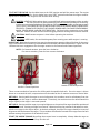
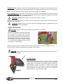
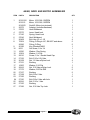
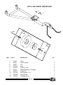
HYDRAULIC TOWABLE
EARTH DRILL
OPERATORS MANUAL
WITH
MAINTENANCE AND
PARTS INFORMATION
0202
1-800-227-7515
P.O. BOX 840
LIVINGSTON, TEXAS 77351
PHONE 936/327-3121
FAX 936/327-4025
Web: www.littlebeaver.com
E-Mail: [email protected]
MFG. BY: LB EQUIPMENT, INC. - LIVINGSTON, TEXAS USA
CUSTOMER SERVICE
Ph: 800/227-7515 or 936/327-3121 or Fax 936/327-4025
ORDERS...
Place your orders by telephone, fax, or mail. When calling, please have your parts
manual handy for reference. Our hours are 8:00 am - 4:30 pm central time, Monday
thru Friday. When ordering by mail or fax, include a description and LITTLE BEAVER
part number for the items you are ordering, your return address, and payment or your
authorization for COD shipment.
All orders are shipped UPS where possible. Freight charges will be added to your
invoice. Some items are oversize, resulting in a higher shipping cost. Power units and
larger augers are shipped via motor freight due to their weight.
PAYMENT TERMS...
COD, Cash in Advance, Visa, Mastercard or NET 30 with approved credit. COD limit
for new accounts is $500.00. Personal or company checks on new accounts will be
held until they clear the bank. To eliminate this delay, you may pay by wire transfer
or send a certified or cashiers check. For a NET 30 open account, please call or write
for a credit application.
SERVICE AND REPAIR...
Your LITTLE BEAVER Earth Drill has been designed for user repair with ordinary hand
tools. No special tools are required. Consult the appropriate section of the parts
manual for instructions.
Service or technical consulation is available, free of charge, from the factory in
Livingston, Texas. We will be pleased to help you with any problems or questions. Just
write, fax, or call. Our hours are 8:00am - 4:30pm central time, Monday thru Friday.
Factory repair is available. If you return a part to the factory, please include the
following information: Your name and return address, a description of the problem
and payment or authorization to return the repaired item COD for the repair and
shipping charges.
RETURNS...
Please call the factory for a return authorization. This will help to ensure that your
parts are handled properly. Include your name and address, customer account #,
invoice # under which the returned parts were ordered, and a brief description of the
problem with the parts or the reason for returning them. Parts to be considered for
warranty must be returned to the factory for inspection within 10 days after receipt
of replacement parts. Be sure to prepay the shipping charges, we will not accept
collect or COD packages.
Our mailing address...
LITTLE BEAVER, Inc.
2009 South Houston
P. O. Box 840
Livingston, Texas 77351
0202
SAFETY ALERT SYMBOL
The symbol shown above is used to call your attention to instructions concerning your personal safety.
WATCH THIS SYMBOL — It points out important safety precautions. It means — ATTENTION! BECOME
ALERT! YOUR PERSONAL SAFETY IS INVOLVED!
Read the message that follows and be alert to the possibility of Personal Injury or Death!
WARNING:
The Engine Exhaust from this product contains chemicals known
to the State of California to cause cancer, birth defects or other reproductive harm.
lllllllllllllllllllllllllllllllllllllllllllllllllllllllllllllllllllllllllllllllllllllllllllllllllllllllllllllllllllllllllllllllllllll
2 YEAR LIMITED WARRANTY
For 2 years from purchase, LITTLE BEAVER, INC. will replace for the original purchaser,
free of charge, any part or parts, found upon examination by any factory authorized
service center, or by the factory at Livingston, Texas, to be defective in material
or workmanship or both. If your equipment can not be repaired, it will be replaced.
All transportation charges on parts submitted for replacement under this warranty must
be borne by purchaser.
There is no other express warranty.
Implied warranties, including those of merchantability and fitness for a particular
purpose, are limited to 2 years from purchase and to the extent permitted by law. Any
and all implied warranties are excluded. This is the exclusive remedy and liability
for consequential damages under any and all warranties are excluded to the extent
exclusion is permitted by law.
*Notice: Engines are warrantied by the manufacturer of the engine. See separate engine
warranty enclosed.
lllllllllllllllllllllllllllllllllllllllllllllllllllllllllllllllllllllllllllllllllllllllllllllllllllllllllllllllllllllllllllllllllllll
MACHINE SERIAL NUMBER
The serial number is located on the top side of the frame. For your convenience, when requiring service
or parts information, refer to this number and your model number. Record the serial number, model
number, engine make and date of purchase in the space provided below:
Serial Number:
Model Number:
Engine Make:
Date of Purchase:
Page O-1
1004
TABLE OF CONTENTS
OPERATORS MANUAL
Page #
O-1
O-2
O-3
O-4
O-5
O-6
O-7
O-8, O-9 & O-10
O-11
Safety Alert, Warranty and Machine Information
Table of Contents
Safety Instructions and Specifications
Maintenance and Lubrication Instructions
Set-up, Handle Adjustments
Set-up, Drive head and Actuator Adjustments
Towing Instructions
Operation
Decal Location
PARTS MANUAL
Page #
P-2 & 3
P-4 & 5
P-6 & 7
P-8 & 9
P-10
P-11
Engine Frame Assembly
Spine and Valve Assembly
Head, Neck & Motor Assembly
Handle and Rock Shaft Linkage Assembly
Hydraulic Tank Assembly
Hitch and Wheel Breakdown
Hydraulic Notes
Prices for Hydraulic Parts and Augers
Inside Back Cover...Torque Information and Conversion Chart
Page 0-2
0202
SAFETY INSTRUCTIONS
DANGER: Failure to observe safety instructions and reasonable safety practices can
cause Property Damage, Serious Bodily Injury and/or Death. BE CAREFUL!! WATCH OUT
FOR BYSTANDERS!!
DANGER: NEVER run engine inside building or enclosed area. Exhaust gases contain carbon
monoxide, an odorless and deadly poison.
DANGER: NEVER drill holes where there is a possibilityof underground power cables or other
hazards. The exact location of underground services must be determined prior to drilling.
Inadvertent severing of telephone, fiber optic or CATV transmission cable, or damage
to sewer pipe is costly; RUPTURING OF GAS OR WATER LINES CAN CAUSE SERIOUS BODILY
INJURY AND/OR DEATH. COMING INTO CONTACT WITH BURIED POWER LINES CAN CAUSE
SERIOUS BODILY INJURY, SEVERE BURNS, AND/OR ELECTROCUTION. Call local utility com
panies or your local "One-Call" number at least 48 hours before digging and have under
ground utilities marked.
DANGER: NEVER tow at a rate of speed greater then 25 mph. Adjust coupler to 2" ball only.
Properly install safety chains.
WARNING: NEVER use hands to search for leaks. Instead, use a piece of cardboard or wood.
Escaping hydraulic fluid under pressure can have sufficient force to penetrate the skin, causing
serious injury. Before disconnecting lines, be sure to relieve pressure. Before applying
pressure, be sure connections are tight and fittings and hoses are not damaged.
WARNING: Augers are not to be used as anchoring devices.
WARNING: ALWAYS store with hitch down on the ground to avoid accidental tipping which may
cause serious injury or death.
CAUTION:
1. READ and understand this operator’s manual and the operator’s manual for the engine.
2. NEVER Remove auger from hole while auger is turning.
3. NEVER Operate auger at less than full throttle.
4. NEVER Operate drill with damaged auger or other damaged or missing parts.
5. KEEP Hands, Feet and Clothing away from moving parts while engine is running.
6. KEEP All safety shields and devices in place.
7. MAKE Certain everyone is clear before operating the machine.
8. WEAR SAFETY GLASSES.
9. KEEP Bystanders away from work area.
10. SHUT OFF Engine to adjust, service or clean the machine.
11. KEEP the SMV identification sign clean. The SMV identification sign must be replaced if it
becomes faded or damaged.
NOTICE
It is the responsibility of the contractor, owner and user to maintain and operate the Earth Drill in
compliance with operating instructions provided. Observe all listed safety instructions and other
reasonable safety practices. LITTLE BEAVER, INC. accepts no responsibility for damages to this machine,
and other property damage and/or bodily injury due to careless or improper operations.
LITTLE BEAVER, INC. does not recommend use of replacement hydraulic motors which would result in
auger shaft torque greater than 400 ft.-lbs. If greater torque is required, please consult factory.
LITTLE BEAVER, INC. reserves the right to make changes in design and changes for improvements upon
its product without imposing any obligation upon itself to install the same upon its products theretofore
manufactured.
Your operators manual offers recommendations for prolonged and satisfactory service.
SPECIFICATIONS
11 HP Honda
6 GPM @ 2500 PSI
100 Micron Suction Screen
10 Micron Replaceable Return Line Filter
6 1/2 Gallon Hydraulic Reservoir
Page O-3
0505
MAINTENANCE AND LUBRICATION INSTRUCTIONS
NOTE: All engines and hydraulic reservoirs are shipped WITHOUT oil.
ENGINE: The engine is shipped without oil or gasoline. Refer to the manufacturers instructions for
proper procedures and recommended fluid.
HYDRAULIC FLUID AND FILTER: The hydraulic reservoir should be filled to the top of the sight gauge
with hydraulic oil before attempting to start the engine. Most premium grade, mineral based oil with antiwear (AW) and anti-foaming additives are suitable. The recommended fluid for normal temperature
operation is ISO VG 46 grade fluid. In colder climates use ISO VG 32 grade and in warmer climates use
ISO VG 68 grade fluid. The hydraulic oil and return line filter (Part # 30280) must be kept clean at all
times, and should be changed after the first 15 hours of operation. The filter and oil should be changed
every three months or after 100 hours of operation; whichever comes first. See Figure 1.
NOTE: The hydraulic fluid and engine
crankcase oil levels should be checked
prior to each days use.
Hyd. Oil Fill Cap
IMPORTANT: All nuts, fasteners, and fittings
must be kept tightened.
Return Line
CAUTION: Escaping hydraulic fluid under
Oil Filter
pressure can have sufficient force to penetrate
the skin, causing serious injury. Before
disconnecting hydraulic lines, be sure to
Sight Guage
relieve pressure. Before applying pressure,
be sure connections are tight and fittings,
pipes and hoses are not damaged. Use a piece
Figure 1
of cardboard or wood, rather than hands, to
search for leaks. If injured by escaping fluid, see a doctor at once. Serious infection or
reaction can develop if proper medical treatment is not administered immediately.
KEEP all hydraulic lines away from moving parts.
HYDRAULIC OIL LEAKAGE
If any hydraulic oil leakage is encountered, shut down the power source and relieve the hydraulic
pressure by moving the actuator lever in both directions. Check and tighten the screw-on fittings on the
end of each hose. If the leakage persists, it may be necessary to replace the associated hose assembly.
If the valve is leaking around the spool (shaft), you may replace the seal kit (Part # 30275-2).
NOTE: To obtain maximum performance from power source, minimum hose size
recommended is 3/8".
EXCESSIVE HEATING
Excessive heating is caused by placing too much down pressure on the auger which causes the oil
pressure to reach relief pressure. Oil flowing over the relief valve generates the heat.
WHEEL BEARINGS
The wheel bearings should be checked annually for excessive end play and proper lubrication. To
remove end play, remove the hub cap and cotter key from the slotted nut. Tighten the slotted nut until
there is a definite resistance to wheel rotation, then back off one slot and intall a new cotter key. Apply
wheel bearing grease generously to wheel bearings as needed.
DECAL LOCATION
The decals which are provided with your machine are shown at the rear of this manual. The decals shown
should be in the locations as described. If any of the decals are missing or illegible, order replacement
decal kit # 37200-D# and install before operating the machine.
Page 0-4
0204
ASSEMBLY
Attach the slow moving vehicle (SMV) emblem bracket to be rear of the frame using (2) 5/16" x 1" hex
bolts and nuts provided. (See SMV emblem picture on Page O-11)
WARNING: ALWAYS tow with the slow moving vehicle (SMV) emblem properly installed.
SET-UP, Handle Adjustments
THREE POSITION HANDLE: The handle may be pivoted 180 degrees and locked into one of three
positions. The handle is shown in the rearward position in Figure 2. To pivot the handle to the forward
position, push and hold in both handle lock levers as shown in Figure 2. Then, pivot the handle
approximately 90 degrees, release the lock levers, and lower the handle to the forward position as
shown in Figure 3. By releasing the lock levers, the lock levers will lock the handle into position. Use
the previously described procedure to pivot the handle from the forward position to the rearward
position. The third position is near the forward position. This position allows for full penetration of
the auger into the soil.
Handle Lock
Lever
Handle Lock
Lever
Handle Lock
Lever
Figure 3
Handle in Forward Position
Figure 2
Handle in Rearward Postion
HANDLE SIDE-TO-SIDE ADJUSTMENT: The handle may be swiveled up to 20 degrees to each side.
Figure 4 shows the handle in the center position with the swivel lock screw tightened and the handle
pinned. (Note: The center position is the only position which is pinned). To swivel the head side-toside, remove the pin and store in the bushing provided, loosen the swivel lock screw by turning
counter-clockwise, swivel the handle to desired position, tighten the swivel lock screw by turning
Swivel Lock
Screw
Pin
Pin stored
Figure 5
Handle in a Side Position
Figure 4
Handle in Center Position
0205
Page O-5
SET-UP, Adjustments cont...
DRIVE HEAD LOCK: The drive head may be locked in storage position or unlocked and allowed to swivel
freely. Figure 6 shows the drive head in the locked (stored) position. To unlock the drive head, move
the head lock lever to the outside, grasp the drive head handle, and pivot the drive head toward the level
position. Figure 7 shows the drive head in the unlocked position where the head is allowed to swivel
freely. To lock the drive head in storage position, pivot the drive head, using the drive head handle, into
the position shown in Figure 6 and the head will lock into position.
Drive head
handle
Drive head
Move to unlock
Head lock lever
Figure 6
Drive head in locked (stored)
position
Figure 7
Drive head in unlocked
position
ACTUATOR LEVER ADJUSTMENT: The actuator lever link may need to be adjusted if the lever develops
an unequal amount of motion for forward and reverse actuation. The actuator lever link may be adjusted
by loosening the stop nut from the clevis, disconnecting the clevis from one end, turn the clevis to
lengthen or shorten the link, reconnect the clevis, and tighten the stop nut to the clevis (See Figure 8).
IMPORTANT: Be sure the connecting pin of the clevis at the rockshaft end of the link is lined up with
the center of the handle pivot bolt when the lever is in the neutral position. If the pin and pivot bolt do
not have common centers, the link from the valve to the rockshaft must be adjusted to achieve common
centers before the actuator lever link is adjusted.
Actuator Lever
Actuator Lever Link
Stop Nut
Clevis
Connecting Pin
Handle Pivot Bolt
Figure 8
Page O-6
TOWING
DANGER: NEVER tow at a rate of speed greater than 25 mph. Adjust coupler to 2" ball only. Properly
install safety chains.
Before connecting the tow bar, Be sure:
1. The engine is stopped.
2. There is no auger attached.
3. The drive head is in the locked position.
4. The handle side-to-side swivel is in the center, locked position.
5. The handle is pivoted and locked in the rearward position.
6. The machine is resting on the wheels and engine frame.
To connect the tow bar, slide the wide end of the tow bar underneath the axle. Then, hook the round
bar on each side of the tow bar to the hooks on the rear side of the axle as shown in Figure 9. Then
lift the tongue of the tow bar up into position and pin to the anchor point underneath the frame
using the 3/4" diameter pin and hairpin cotter as shown in Figure 10.
Pin
Hairpin
Cotter
Figure 10
Figure 9
WARNING: ALWAYS tow with the slow moving vehicle (SMV) emblem properly installed.
WARNING: NEVER tow with the engine running
CAUTION: ALL nuts, fasteners, fittings, caps and threaded adjustment parts must be kept
tightened. Be aware that improperly tightened components may become loose while towing. (See
torque chart at the end of the manual).
CAUTION: Be sure to comply with all state and highway regulations when towing.
NOTE:
0205
To improve towing performance, it is recommended to inflate tires to a cold inflation
pressure of 25 psi to 30 psi.
Page O-7
OPERATION
BEFORE STARTING THE ENGINE,_Be sure that:
DANGER: NEVER run engine inside building or enclosed area. Exhaust gases contain carbon
monoxide, an odorless and deadly poison.
1.) Engine is properly prepared to Manufacturer’s specifications. Note: Engines with “Oil
Guard” protection must be filled with oil to full mark on dipstick or to point of
overflowing to allow the engine to start.
2.) Hydraulic Reservoir is filled to top of sight gauge.
3.) The tow bar is detached.
4.) Unlock the drive head and attach the auger to drive head adaptor. Make sure the snap
button, in the auger, and hole provided in the adaptor are aligned and the button snaps
securely into place.
5.) Make machine set-up adjustments for drilling the hole. Pivot the handle forward for regular
drilling as shown in Figure 11A or pivot the handle rearward for up-close drilling as shown in
Figure 11B. If necessary, swivel the handle to the side for drilling, vertical hole on unlevel
terrain as shown in Figure 12.
Figure 11B
Up-close Drilling
Figure 11A
Regular Drilling
Figure 12
6.) Move the machine to the drilling site with the drive head in the locked position. Push the
handle downward to a balanced position for moving the machine.
7.) The stop switch on the handle is in the "ON" position. (See Figure 13)
8.) The switch on the engine is in the "ON" position.
Stop Switch
Figure 13
Page O-8
0205
TO START THE ENGINE: Set the choke lever to the “ON” position and pull the starter rope. The engine
should start after 2 or 3 pulls. Set the choke lever to the “OFF” position and allow the engine to warmup for 2 or 3 minutes. Run engine at full throttle while drilling.
DANGER: NEVER drill holes where there is a possibilityof underground power cables or other
hazards.
The exact location of underground services must be determined prior to drilling.
Inadvertent severing of telephone, fiber optic or CATV transmission cable, or damage to sewer
pipe is costly; RUPTURING OF GAS OR WATER LINES CAN CAUSE SERIOUS BODILY INJURY AND/
OR DEATH. COMING INTO CONTACT WITH BURIED POWER LINES CAN CAUSE SERIOUS BODILY
INJURY, SEVERE BURNS, AND/OR ELECTROCUTION. Call local utility companies or your local
"One-Call" number at least 48 hours before digging and have underground utilities marked.
CAUTION: MAKE certain everyone is clear before operating the machine.
CAUTION: KEEP hands, feet and clothing away from moving parts while engine is running.
IMPORTANT: Note that the actuator lever must be depressed on opposite sides of the lever for the same
auger rotation when the handle is pivoted between the forward and rearward positions. Figure 14A and
14B show the lever engagement for the auger rotation in the forward and rearward positions.
NOTE: For forward rotation, pivot the lever clockwise.
For reverse rotation, pivot the lever counter-clockwise.
Forward
Reverse
Reverse
Forward
Figure 14B
Handle in rearward position
Figure 14A
Handle in forward position
There are two methods of operation for drilling with the towable hydraulic. Since the auger is driven
about an arc around the axle, compensation must be made for the arc motion to ensure a vertical hole.
METHOD I: Starting with the auger in vertical alignment, the machine must be rolled away from the
auger slightly as the auger is advance downward. Conversely, the machine must be rolled toward the
auger slightly as the auger is removed upward.
METHOD II: Starting with the auger in an angled alignment, the point of the auger should be positioned
away from the axle, creating an angle from vertical. Without moving the position of the wheels or axle,
advance the auger to the desire depth. At the desired depth, the top of the auger should be in vertical
alignment with the botton of the auger. This procedure will allow the removal of the auger from the hole
without moving the position of the wheels or axle.
START THE AUGER TURNING, By pulling the actuator lever in completely. Always allow the auger to
turn at full speed and let it cut its way into the soil.
Page O-9
IMPORTANT: When digging in soft soil, hold up slightly on auger. In hard pan, apply pressure, but not
enough to stall the auger or slow it down significantly. The auger works best when it turns at full speed.
NOTE: Only use reverse to free the auger if it becomes lodged in the ground.
IF THE AUGER STALLS repeatedly or slows down significantly; stop the auger by releasing actuator
lever, slightly lift up on auger, start auger by pulling actuator lever, and allow the auger to turn at full
speed while slowly lowering it to bottom of hole.
CAUTION: NEVER Remove auger from hole while auger is turning.
When the desired depth is reached, stop the auger by releasing the actuator lever. Then pull the auger
completely out of the hole.
CAUTION: Keep the back as vertical as possible by bending the legs, as required, during the
operation and lifting procedure.
AUGER EXTENSIONS
CAUTION: Stop the engine when making auger/extension connections.
If greater hole depths are required, extensions
may be used with the auger. After the auger
has reached its maximum depth, stop the
engine and disconnect the drive adaptor from
the auger which remains in the hole. Connect
the extension to the auger as shown in figure
15. Connect the drive adaptor to the extension
and continue to dig the hole.
FIGURE 15
When the desired depth is reached, stop the engine and disconnect the drive adaptor from the
extension then remove the extension(s) and auger from the hole.
CAUTION: When working with cutting blade, point and auger flighting; be careful not to be
cut by sharp edges.
A
CUTTING BLADE
B
Check the cutting blade (Item A, Figure 16) on the auger
frequently. If it becomes dull, it may be reversed to use the other
cutting edge. If the outside of the blade wears even with the
auger flighting, replace the blade or rebuild it with a hard
surfacing rod. This is very important to reduce auger flighting
wear and damage. The point (Item B, Figure 16) should be
replaced when it loses its cutting shape.
Page O-10
0205
DECAL
LOCATION
DRIVE HEAD
DRIVE HEAD
SMV EMBLEM AND
REFLECTOR STRIPS
TOW BAR
0505
Page O-11
TROUBLESHOOTING
TROUBLE
CAUSE
Engine will not start
1)
2)
3)
4)
5)
Cannont connect or
disconnect auger
1) Foreign matter clogging auger adaptor
2) Spring and button in top of auger is bent or broken
Auger turns too slowly
and will not dig
1) Too much downward pressure or binding on side of hole. Hold
back if necessary to allow auger to turn at full speed.
2) Linkage between control lever and valve is mis-adjusted. With engine
off, ensure that neither lever touches handle bar when moved to full
forward or reverse position. Re adjust linkage if necessary.
Stop switch in off position on handle
Engine stop switch is in "off" or "O" position
Low fuel level in gas tank
Low oil level in "Oil Guard" or "Oil Alert" equipped engines
Spark plug fouled
Auger turns but will not dig 1) Foreign matter collected around point
2) Point or blade is dull
3) Wrong blade type for soil condition. Contact your dealer or factory
for Little Beaver carbide blade
Auger with extension will
not dig
1) Auger or extension bent or running out of line
2) Number of extensions exceeds capacity of machine
Hydraulic oil and/or hoses
overheats
1) It is normal for the hoses and reservoir to be warm to the touch.
If it is very hot, consult your dealer or factory.
Auger will not stop turning
when lever is released.
1) Valve or linkage is binding. Do not use. Consult your dealer or factory.
Problems not listed in table
1) Consult your dealer or factory.
Page O-12
0205
TOWABLE PARTS MANUAL
NOTES:
ENGINE FRAME ASSEMBLY
9
\
24
\
8 ---
--- 15
--- 26
--- 30
--- 23
Engine
2 ---
18
\
21 --22 ---
7 ---
\
14
16 --17 ---
\
15
10
3 ---
/
11
/
4 --5 ---
12
/
11
/
6 ---
\
18
\
10
/
19
\
20
1 ---
--- 13
Page P-2
R
0302
ENGINE FRAME ASSEMBLY
ITEM
PART #
DESCRIPTION
QTY
1
2
3
4
5
6
37039
37120
30268
30269
30267-58
30263-D2
30314-P#
30314-D#
37159-P
37159
37164
37163
37124
30164
9096
37179
4081
30154
3012-3
3012-2
30171
30168
9027-8
30270-3
37161
37212
30204
30318
9024
3002-B
3001-11H
9024-1
Frame, Engine
Bracket, Pump
Flexible Coupling, 1" Bore
Spider, Flexible Coupling
Flexible Coupling, 5/8" Bore
Pump, Hydraulic
Seal Kit, Prince Pump, SN 6657 and above
Seal Kit, Dowty/Parker Pump
Hose Assy. Pump to Valve, SN 6657 and above
Hose Assy. Pump to Valve
Emblem, SMV ID
Bracket, SMV Emblem
Bolt, Hex 3/4 x 2-1/2
Washer, 3/4 Flat, SAE
Nut, 3/4 Nylon Lock
Cap Screw, Socket Head, 3/8 x 1-3/4
Key, Engine Shaft
Nut, 3/8 Nylon Lock (pump mounting)
Washer, 3/8 Lock
Bolt, Hex, 3/8 x 1
Set Screw, 5/16 x 5/16
Key, Woodruff #505
Bolt, Hex 3/8 x 1-1/4
Clamp, Hose
Fitting, 1-1/16 x 3/4 Bead
Fitting, 7/8 x 3/4 Bead, SN 6657 and above
Nut, 1/4 Nylon Lock
Nut, 5/16 Nylon Lock
Bolt, Hex 1/4 x 7/8
Washer, 3/8 Flat, Heavy
Engine, 11 HP Honda
Bolt, Hex 5/16 x 1
1
1
1
1
1
1
1
1
1
1
1
1
2
2
2
4
1
4
4
4
2
1
2
2
1
1
4
2
2
4
1
2
7
8
9
10
11
12
13
14
15
16
17
18
19
20
21
22
23
24
25
26
30
31
Page P-3
0910
R
12 ---
--- 11
14
13 ---
/
30--
--- 10
15
/
-- 16
33--
32 ---
/
17
7 ---
31 ---
6 ---
-- 18
/
8
1 ---
9 ---
19 ---
/
20
/
22
SPINE & VALVE
ASSEMBLY
/
23
/
21
/
24
27 ---
26
/
25
/
27---------
--- 2
5 ----- 28
--- 4
--- 3
--- 29
Page P-4
R
0204
SPINE & VALVE ASSEMBLY
ITEM
PART #
DESCRIPTION
QTY
1
2
3
4
37022
Spine Assembly
Hydraulic Tank (see page P-10 for breakdown)
Wheel Assembly (see page P-11 for breakdown)
Axle Assembly (includes Wheels
Axle ONLY
Hose, Tank to Pump
Hose, Valve to Tank
Valve, 4-way with Relief
Seal Kit, Valve
Angle, Neck Lock
Cap, Filler Breather
Neck Lock Screw
Knob, Handle
Adaptor #6410-6-8
Nut, Hex 1/4 w/Nylon Lock
Pin, Clevis, 3/16 x 3/4
Clevis, 5/16 NC
Nut, Hex 5/16
Cotter Pin, 3/32 x 5/8
Nut, 1/2 Slotted
Bolt, 1/2 x 1-1/2 Hex
Pin, Ball Lock, 3/8
U-Bolt, 1/2"
Cotter Pin, 1/8 x 1
Bolt, 1/4 x 2 Hex
Bushing, 3/4 male x 1/2 female
Clamp, Hose
Bolt, 5/16 x 1 Hex
Bushing
Nut, 1/2 Hex w/Nylon Lock
Bolt, 1/2 x 2-1/2 Hex
Washer, Flat #10
Hose Assembly, Valve to Motor, Left Hand
Hose Assembly, Valve to Motor, Right Hand
Roll Pin, 3/16 x 1
1
1
2
1
1
1
1
1
5
6
7
8
9
10
11
12
13
14
15
16
17
18
19
20
21
22
23
24
25
26
27
28
29
30
31
32
33
0204
37004
37000
37001
37162
37157
37141
30275-2
37082
37165
37085
37088
37155
30204
37171
37138
3002-D
30179
37134
30408
37181
37133
30163
5076
30282
30270 -3
9024-1
37123
30158
6533
4033-1
37197
37198
KT039
1
1
1
2
2
2
2
1
1
1
2
4
1
1
2
2
1
1
2
2
2
2
1
1
1
Page P-5
R
HEAD, NECK AND MOTOR
ASSEMBLIES
\
7---
8 ----- 1
---9
---10
--- 2
--- 11
--- 12
--- 13
--- 14
--- 3
\
15 --5 ---
--- 4
16 ---
7
/
18 --19 --20 ---
17 --27 --22
/
--- 23
--- 15
\
24
25 ---
7
/
/
20
--- 26
--- 27
Page P-6
R
6
/
0204
HEAD, NECK AND MOTOR ASSEMBLIES
ITEM
PART #
DESCRIPTION
QTY
1
30191-S2
30191-5
30162-D
30272
37053
37075
37145
37046
30408
70304
30296
30182
9021
10520
10304
30010
37132
30158
37131
10305
36412
37172
37127
37128
37126
37130
9024-1
37125
37182
Motor, 103-1028, 150RPM
Motor, 103-1029, 125RPM
Seal Kit, Motor (not pictured)
Adaptor, (includes hardware)
Head Weldment
Lever, Head Lock
Spring, Head Lock
Neck Weldment
Bolt, Hex 1/2 x 1-1/2
Fitting, O-Ring to JIC, SN 6657 and above
Fitting, O-Ring
Key, Woodruff #806
Set Screw, 1/4 x 1/4
Washer, Disc Spring
Washer, 1/4 Flat
Screw, 1/4 x 1 Socket Head Cap
Bolt, 5/16 x 2-3/4 Hex
Nut, 1/2 Hex w/Nylon Lock
Bushing
Washer, 5/16 Flat
Nut, 5/16 Hex w/Nylon Lock
Washer, 5/8 Flat SAE
Bushing
Bolt, 5/8 x 2 Hex
Bushing
Bolt, 5/8 x 2 Hex with hole
Bolt, 5/16 x 1 Hex
Bushing
Nut, 5/16 Hex Top Lock
1
1
1
1
1
1
1
1
4
2
2
1
1
1
1
1
1
4
1
1
2
2
2
1
2
1
1
1
1
2
3
4
5
6
7
8
9
10
11
12
13
14
15
16
17
18
19
20
22
23
24
25
26
27
Page P-7
00910
R
HANDLE AND ROCK
SHAFT LINKAGE
--- 1
5 ---
--- 2
8 ---
9 ---
6 ---
11 ---
--- 3
15 --14 ---
--- 4
7 ---
--- 10
--- 13
--- 12
15 ---
--- 6
--- 6
16 --17 ---
4 ---
18
/
14
12--11---
/
10
/
--- 13
19 --12--13--14 ---
--- 20
--- 21
--- 10
--- 11
--- 22
23 ---
Page P-8
R
0204
HANDLE AND ROCK SHAFT LINKAGE
0204
ITEM
PART #
DESCRIPTION
QTY
1
2
3
4
5
6
7
8
9
10
11
12
13
14
15
16
17
18
19
20
21
22
23
37061
37101
37144
37140
3002-A
30318
10470
37137
37093
37138
37171
30179
4033-1
3002-D
3010-9
37100
37143
37097
37089
37135
37092
37136
37146
Handle Weldment
Handle Lock, Left
Spring, Handle Lock Left
Bushing
Bolt, Hex 5/16 x 1-3/4
Nut, Hex 5/16 w/Nylon Lock
Kill Switch Assembly
Bushing
Lever, Valve
Clevis, 5/16 NC
Pin, Clevis, 3/16 x 3/4
Cotter Pin, 3/32 x 5/8
Washer, Flat #10
Nut, Hex, 5/16
Bolt, Hex, 5/16 x 2
Handle, Lock, Right
Spring, Handle Lock Right
Link, Lever
Rockshaft
Retaining Ring, External 13
Bar, Rockshaft End
Cap Screw, Socket Head 5/16 x 2
Link, Valve
1
1
1
2
1
3
1
1
1
3
3
3
3
3
2
1
1
1
1
1
1
1
1
Page P-9
R
--- 14
HYDRAULIC TANK ASSEMBLY
--- 13
--- 15
--- 4
11 ----- 12
10 --5 ---
A
ITEM
16 --17 ---
A
1
2
3
4
5
6
7
8
9
10
11
12
13
14
15
16
17
9 ---
--- 8
7 ---
/
6
/
--- 4
5
PART #
DESCRIPTION
QTY
37005
37006
30262
30159
30312
30310
30266
37020
37019
37016
35286
9-30023
35290
37021
30281
30280
3012-1T
3002-C
Hydraulic Tank Assy Complete 1
Hydraulic Tank Weldment
1
Sight Gauge Assembly
1
Plug, Magnetic, 1/2
1
Elbow, 3/4 Standard
2
Nipple, 3/4 x 2-1/2
2
Strainer, Suction
1
Pipe, Inlet
1
Pipe, Return
1
Lid, Hydraulic Tank
1
Elbow, 90, 3/4 NPT
1
Coupling, 3/4 NPT
1
Nipple, Close, 3/4 NPT
1
Pipe, Return Filter
1
Filter Base
1
Filter
1
Bolt, Hex 5/16 x 3/4
10
Washer, Lock 5/16
10
--- 1
--- 2
3 --Page P-10
R
0602
HITCH AND WHEEL BREAKDOWN
--- 2
--- 3
1 ---
Axle
12
/
4
/
5
6
--- 9
/
5
ITEM
PART #
1
2
3
4
5
6
9
10
11
12
0111
37105
9059-1
36433
37004-3
37004-4
37004
37004-7
37004-6
37004-8
37004-P
DESCRIPTION
/
10
/
11
QTY
Hitch
Cotter, hairpin
Pin
Seal
Bearing, Cone
Wheel Assembly, Complete
Cotter Pin
Nut, Spindle, 1-14
Cap, Grease
Tire/Wheel only
1
1
1
1
2
2
1
1
1
1
Page P-11
R
NOTES:
IMPORTANT: All nuts, fasteners, and fittings must be kept tightened. Refer to
torque chart for proper assembly torque.
TORQUE INFORMATION
HEX HEAD
TYPE
GRADE
5
SOCKET
GRADE
8
WRENCH SIZE
WRENCH SIZE
inch
SIZE
No. 4
8 in lb
12 in lb
1/4"
12 in lb
3/32"
No. 6
16 in lb
23 in lb
5/16"
21 in lb
7/64"
No. 8
30 in lb
41 in lb
11/32"
42 in lb
9/64"
No.10
43 in lb
60 in lb
3/8"
60 in lb
5/32"
1/4"
8 ft lb
12 ft lb
7/16"
12 ft lb
3/16"
5/16"
17 ft lb
25 ft lb
1/2"
24 ft lb
1/4"
3/8"
30 ft lb
45 ft lb
9/16"
43 ft lb
5/16"
7/16"
50 ft lb
70 ft lb
5/8"
69 ft lb
3/8"
1/2"
75 ft lb
110 ft lb
3/4"
105 ft lb
3/8"
9/16"
110 ft lb
150 ft lb
13/16"
158 ft lb
-----
5/8"
150 ft lb
220 ft lb
15/16"
195 ft lb
1/2"
3/4"
260 ft lb
380 ft lb
1-1/8"
353 ft lb
5/8"
HYDRAULIC FITTINGS
0196
SIZE
TORQUE
1/4 NPT
3/8 NPT
1/2 NPT
3/4 NPT
25 ft.lb.
50 ft.lb
75 ft.lb.
110 ft.lb.
SIZE
7/16-20
9/16-18
3/4-16
7/8-14
1-1/16-12
SAE
SAE
SAE
SAE
SAE
TORQUE
O-Ring
O-Ring
O-Ring
O-Ring
O-Ring
12 ft.lb.
20 ft.lb.
35 ft.lb.
50 ft.lb.
70 ft.lb.
TH I N K
SAFET Y
FI RST!
P.O. BOX 840
LIVINGSTON, TEXAS 77351
PH# 936/327-3121
FAX# 936/327-4025