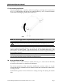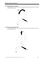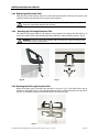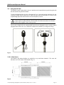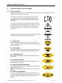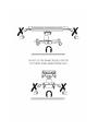
1
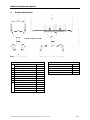
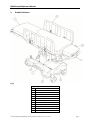
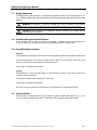
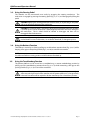
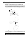
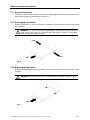
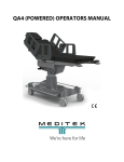
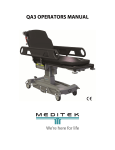
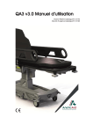
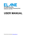
QA4 (MANUAL) OPERATORS MANUAL
QA4 Powered Operators Manual
Contents
1. Introduction
.
.
.
.
.
1.1.
Warnings and Cautions .
.
.
1.2.
Scope of Use
.
.
.
.
1.3.
Equipment Classification .
.
.
2. Product Specifications
.
.
.
.
3. Product Functions .
.
.
.
.
3.1.
Height Adjustment
.
.
.
3.1.1. Problems Raising the Patient Platform
3.1.2. Pump Bleeding Instructions .
.
3.2.
Using the Brakes .
.
.
.
3.3.
Using the Steering Pedal .
.
.
3.4.
Using the Backrest Function
.
.
3.5.
Using the Trendelenburg Function .
.
3.6.
Using the Head Section .
.
.
3.7.
Using the Leg Section
.
.
.
3.7.1. Removing the Leg Section .
.
3.7.2. Replacing the Leg Section .
.
3.7.3. Articulating Leg Section (optional) .
3.8.
Using the Stretcher Sides .
.
.
3.8.1. Rotating the Stretcher Sides .
.
3.8.2. Removing the Stretcher Sides
.
3.8.3. Replacing the Stretcher Sides
.
3.8.4. Attaching the Full Length Stretcher Side
3.8.5. Rotating the Full Length Stretcher Side
3.9.
Using the I.V. Pole .
.
.
.
3.10. C-Arm Access
.
.
.
.
4. Patient Weight Limits
.
.
.
.
5. K8 Pressure Care Mattress .
.
.
.
5.1.
Infection Control .
.
.
.
6. Cleaning and Disinfecting the Stretcher
.
.
6.1.
Cleaning .
.
.
.
.
6.2.
Disinfecting
.
.
.
.
7. Product Maintenance
.
.
.
.
8. Identifying Product Labels and Symbols
.
.
8.1.
Common Symbols
.
.
.
8.2.
Steer Label
.
.
.
.
8.3.
Brake Label
.
.
.
.
8.4.
Leg Section Label .
.
.
.
8.5.
Head Section Label
.
.
.
8.6.
Articulating Leg Section Label
.
.
8.7.
Raise and Lower Label
.
.
.
Page
.
.
.
.
.
.
.
.
.
.
.
.
.
.
.
.
.
.
.
.
.
.
.
.
.
.
.
.
.
.
.
.
.
.
.
.
.
.
.
.
.
.
.
.
.
.
.
.
.
.
.
.
.
.
.
.
.
.
.
.
.
.
.
.
.
.
.
.
.
.
.
.
.
.
.
.
.
.
.
.
.
.
.
.
.
.
.
.
.
.
.
.
.
.
.
.
.
.
.
.
.
.
.
.
.
.
.
.
.
.
.
.
.
.
.
.
.
.
.
.
.
.
.
1
1
1
1
2
3
4
4
4
4
5
5
5
6
7
7
7
8
8
9
9
10
10
10
11
11
12
12
12
13
13
13
13
14
14
14
14
14
14
14
14
© Portsmouth Surgical Equipment Ltd and Anetic Aid Ltd. All rights reserved; this document is not to be reproduced in whole or in part
without the permission of the copyright owners. The company reserves the right to modify or improve the equipment referred to.
QA4 Powered Operators Manual
1.
Introduction
These instructions are intended to assist you with the operation of the QA4 Day Surgery Stretcher.
It is important that these instructions are read thoroughly before using the equipment.
It is also important to check the stretcher before use; ensure that all stretcher functions operate to
their full range of movement and that all detachable components disengage, re-engage and lock
correctly. We recommend that the stretcher is visually inspected for any loose or damaged parts,
foreign objects caught in the castors, and hydraulic fluid leakage.
1.1. Warnings and Cautions
Various warnings and cautions are made throughout these operating instructions.
A WARNING is given when the personal safety of the patient or user may be affected and
when disregarding this information could result in injury.
A CAUTION is given when special instructions must be followed. Disregarding this
information could result in permanent damage being caused to the stretcher.
1.2. Scope of Use
This product is intended for use within a day surgery environment for the induction, transport,
treatment and recovery of patients.
While the stretcher can be used to transfer patients out of a surgical environment, the stretcher has
not been designed as a patient transfer stretcher, as it has very low ground clearance that may
cause problems when traversing uneven ground.
CAUTION: The stretcher may be damaged by pushing it across rough or uneven ground.
1.3. Equipment Classification
The stretcher has been classified as a ‘Class 1' device.
© Portsmouth Surgical Equipment Ltd. Document No. 992008. Issue 11 – 19.07.11
Page 1
QA4 Powered Operators Manual
2.
Product Specifications
Fig. 1
Key to Fig. 1
Height (MIN)
A.
Height (MAX)
B. Mattress Length
C. Stretcher Length
D. Mattress Width
E. Stretcher Width (With Side Rails)
F. Stretcher Width (With Sides)
G. Stretcher Width (Brakes Off)
H. Base Length
Mattress Depth
Trendelenburg
Reverse Trendelenburg
Backrest Articulation
Head Section Articulation
22.75”
36.75”
80.25”
82.75”
23.5”
25.75”
30.25”
32.75”
41.5”
3”
20°
12°
0°-80°
+30°/-30°
Weight Limits
Stretcher
Head Section
Leg Section
Stretcher Weight
Castor Diameter
© Portsmouth Surgical Equipment Ltd. Document No. 992008. Issue 11 – 19.07.11
350 lbs.
55 lbs.
110 lbs.
275 lbs.
6”
Page 2
QA4 Powered Operators Manual
3.
Product Functions
Fig. 2
Key to Fig. 2
1.
Raise and Lower Pedals
2.
Brake Pedals
3.
Steering Pedal
4.
Backrest Actuation Lever
5.
Trendelenburg Actuation Lever
6.
Head Section Tilt Actuation Lever
7.
Removable Leg Section
8.
Stretcher sides
9.
Pushing Handles
10. Oxygen Cylinder Mounting Trough
11. I.V. Pole
12. ‘V’ Mounting for Suction Canister
© Portsmouth Surgical Equipment Ltd. Document No. 992008. Issue 11 – 19.07.11
Page 3
QA4 Powered Operators Manual
3.1. Height Adjustment
The height of the patient platform is adjusted by using either of the ‘raise and lower pedals’ (Fig. 2,
no. 5). Pumping either pedal will raise the patient platform, lifting either pedal will lower the patient
platform.
WARNING: Ensure there is nothing to impede the raising or lowering of the patient
platform as this could result in damage to the equipment and/or injury to the patient.
CAUTION: Ensure that there is no equipment stored in the base of the stretcher before
lowering the patient platform.
3.1.1. Problems Raising the Patient Platform
If the stretcher will not ascend, or excessive pumping is required to raise the stretcher to its
maximum height, the stretchers pump may need bleeding to remove a build-up of air.
3.1.2. Pump Bleeding Instructions
Priming
Two people will be required as both the raise and lower pedals need to be operated simultaneously.
One person lifts either of the raise and lower pedals & holds it in this position while the second
person pumps the other raise and lower pedal for 20 strokes.
Switch sides and repeat this procedure.
Cycling
Pump either of the raise and lower pedals to position the top as high as it will go and continue to
pump for a further 10 strokes.
Fully lower the stretcher and repeat on the same side.
Switch sides and repeat the procedure.
It may be necessary to repeat these procedures up to three times to fully bleed the pump.
3.2. Using the Brakes
All four castors are locked simultaneously by depressing either of the brake pedals (Fig. 2, no. 2) at
any point along the length of the pedal. The brakes are disengaged by lifting either pedal.
© Portsmouth Surgical Equipment Ltd. Document No. 992008. Issue 11 – 19.07.11
Page 4
QA4 Powered Operators Manual
3.3. Using the Steering Pedal
The stretcher can be manoeuvred more easily by engaging the steering mechanism. The
mechanism is engaged by pressing the steering pedal (Fig. 2, no. 3) and disengaged by lifting the
pedal.
CAUTION: Applying the steering pedal with excessive force, i.e. by standing on the pedal,
will cause permanent damage to the mechanism.
CAUTION: The steering pedal is designed to disengage automatically when the stretcher
is pushed leg first over an obstruction. Attempting to prevent this will cause damage to
the mechanism. The 5th wheel should be allowed to disengage and then can be
reengaged after the obstruction.
CAUTION: The steering wheel must be disengaged manually when the stretcher is
pushed head first over an obstruction, i.e. an elevator threshold, or damage may occur.
3.4. Using the Backrest Function
The backrest is moved up or down by pulling up on the backrest actuation lever (Fig. 4, no. 2) whilst
keeping a firm grip on the pushing handle (Fig. 2, no. 10) to control the movement.
NOTE: It is important to note that the backrest provides only minimal lift assistance; the patient
should be assisted into a sitting position and the backrest articulated up.
3.5.
Using the Trendelenburg Function
The patient platform can be moved into a trendelenburg or reverse trendelenburg position by
pulling up on the trendelenburg actuation lever (Fig. 2, no. 5) while maintaining a firm grip on the
pushing handles (Fig. 2, no. 9) to control the movement.
CAUTION: When the patient is positioned over the perineal cut out the patient weight is
offset towards the foot end of the stretcher and the patient platform is no longer evenly
balanced. Extra effort will be required to tilt the stretcher top into a head down position.
© Portsmouth Surgical Equipment Ltd. Document No. 992008. Issue 11 – 19.07.11
Page 5
QA4 Powered Operators Manual
3.6. Using the Head Section
The head section is articulated by simply pulling up on the head section tilt actuation lever.
The head section is also designed to be removed for specific procedures; i.e. gynaecology and
urology to give greater anaesthetist access to the patient. Removing the head section prior to
administering anaesthetic reduces the length of the backrest and the need to reposition the patient
in surgery. Removing the head section also gives greater access to the patient from the head end
for staff.
Lower
Lift
Fig. 3
Remove
Fig. 4
The head section is removed by lifting the release handle, then lowering and removing the head
section from the support bracket.
WARNING: When the head section is attached to the stretcher ensure that the head
section is fully engaged and securely locked in position.
© Portsmouth Surgical Equipment Ltd. Document No. 992008. Issue 11 – 19.07.11
Page 6
QA4 Powered Operators Manual
3.7. Using the Leg Section
The stretcher comes standard with a non-articulating lightweight leg section, if the stretcher has an
articulating leg section installed, refer to section 3.7.3.
3.7.1. Removing the Leg Section
Depress both buttons as shown (one button is located on each side of the stretcher) and remove
the leg section.
WARNING: Ensure that any persons responsible for removing the leg section adopt
good posture and stance, in accordance with the relevant ‘Moving and Handling’
policies, to prevent injury to the user.
Push
Pull
Push
Fig. 5
3.7.2. Replacing the Leg Section
Engage the locating spigots of the leg section as shown and push firmly until the leg section is fully
engaged.
WARNING: Ensure that the leg section is fully engaged and securely locked in position.
Push
Fig. 6
© Portsmouth Surgical Equipment Ltd. Document No. 992008. Issue 11 – 19.07.11
Page 7
QA4 Powered Operators Manual
3.7.3 Articulating Leg Section
The articulating leg section is moved up and down by pulling up on the leg section actuation lever
(Fig. 7, no. 1) whilst keeping a firm grip on the pushing handle (Fig. 7, no. 2) to control movement.
To remove the articulating leg section, refer to section 3.7.1.
Fig. 7
NOTE: The articulating leg section is an optional accessory for this stretcher.
CAUTION: When tilting the stretcher into a reverse trendelenburg position ensure the
articulating leg section is returned to a horizontal position or damage may occur.
NOTE: With the articulating leg section, the leg section should be articulated down to the
maximum angle before being removed. This shortens the distance between the end of the leg
section and the mounting sockets. This does two things; one, it provides better access to the
release buttons, and two, it reduces the distance that the user has to reach to support the weight of
the articulating leg section.
NOTE: When replacing the articulating leg section pull the actuation handle to operate the gas
struts and allow the location spigots to achieve a horizontal position.
3.8. Using the Stretcher Sides
The stretcher comes standard with four stretcher sides (Fig. 2, no. 8) that can be individually
removed from the stretcher or rotated through 180 degrees.
Each side is mounted into a fixed socket that is labelled with a position number, (1) - (4), this
corresponds with the numbered label on the stretcher side and ensures that each stretcher side is
correctly positioned.
See the following sections for more information on rotating, removing and replacing the stretcher
sides.
© Portsmouth Surgical Equipment Ltd. Document No. 992008. Issue 11 – 19.07.11
Page 8
QA4 Powered Operators Manual
3.8.1. Rotating the Stretcher Sides
Depress the button as indicated, see Fig. 8, and rotate the stretcher side, the side will automatically
relock in the next position.
Rotate
Push
Fig. 8
3.8.2 Removing the Stretcher Sides
Ensure the stretchers side is in the ‘up’ position, depress the button as indicated, see Fig. 9, and
remove the stretcher side.
Lift
Push
Fig. 9
© Portsmouth Surgical Equipment Ltd. Document No. 992008. Issue 11 – 19.07.11
Page 9
QA4 Powered Operators Manual
3.8.3 Replacing the Stretcher Sides
Align the stem of the stretcher side to the socket and let the stretcher side drop into position, the
stretcher side will automatically lock in position when replaced.
CAUTION: Ensure that the stretchers sides are located into their respective numbered
sockets to prevent the stretcher sides clashing.
3.8.4 Attaching the Full Length Stretcher Side
The optional full length stretcher side attaches to the stretcher by hooking onto the side bar. To
secure the stretcher side, rotate the locking clamp handle 90° in either direction, shown in Fig. 10
WARNING: Failure to secure the stretcher side to the side bar using the locking clamp
could result in injury to the patient.
Fig. 10
Fig. 11
3.8.5. Rotating the Full Length Stretcher Side
When the stretcher side is secured to the stretcher, as shown in Fig. 11, pull the handle in the up
direction as indicated in Fig. 12 and rotate the stretcher side away from the stretcher into the down
position. The stretcher side will automatically relock in the down position.
Fig. 12
© Portsmouth Surgical Equipment Ltd. Document No. 992008. Issue 11 – 19.07.11
Page 10
QA4 Powered Operators Manual
3.9. Using the I.V. Pole
The stretcher comes standard with a loose I.V. pole that can be attached at any point along the side
bar and secured using the hand-wheel.
To adjust the height of the I.V. pole, as illustrated in Fig. 13; grasp the locking mechanism (A) and
using your thumb, lift the mechanism to release the lock and move the pole up or down to the
required height (B); release the mechanism to lock the pole in position.
CAUTION: When adjusting the height of the pole use two hands; one to adjust the
height of the inner pole and hooks, and the other to hold the outer pole to ensure that it
remains fully engaged in the mounting socket.
The I.V. pole is fitted with two spring-loaded hooks that are designed to return to their original
upright position when not in use. Swivel one or both hooks outwards (C) to hang the I.V. bags.
Fig. 13
3.10. C-Arm Access
The mattress and patient platform are made from x-ray translucent materials. The areas and
dimensions of C-Arm access are illustrated in Fig. 14.
Fig. 14
© Portsmouth Surgical Equipment Ltd. Document No. 992008. Issue 11 – 19.07.11
Page 11
QA4 Powered Operators Manual
4.
Patient Weight Limits
1. Main Body: The stretcher is designed to accommodate a maximum patient weight of 350 lbs.
Patients should mount the stretcher at the centre of the patient platform and their weight
kept as evenly distributed as possible whilst on the stretcher. Patients must not sit at either
end of the stretcher as this will result in tipping.
2. Head Section: The head section is designed to take a maximum weight of 55 lbs.
3. Leg Section: The leg section is designed to take a maximum weight of 110 lbs.
WARNING: Exceeding any of the maximum specified weight limits could result in failure
of the stretcher and injury to the patient and staff.
5.
K8 Pressure Care Mattress
Understanding the needs for greatest possible patient pressure area care, the mattress is
manufactured using the most up to date materials and manufacturing methods available. They
consist of:
1. Body Mould Visco Foam: Through its sensitivity to temperature this gel feel foam actually
moulds to the patient’s body, relieving pressure by distributing the load as evenly as possible.
2. Flexi-Fabric: A polyurethane water resistant vapour permeable outer cover with the
properties of Lycra ensures maximum effect of the body mould foams.
3. Pressure Care Properties: The effective pressure care properties of the mattress will decline
below satisfactory levels after 4 years at which time we recommend the mattress be replaced.
NOTE: An independent pressure care report produced by Salford University is available upon
request.
CAUTION: Do not press the mattress with sharp objects or store items on top of the
mattress or repair tears and splits with adhesive tape as contamination may occur.
5.1. Infection Control
Ultrasonic welding of materials creates an impervious seal ensuring an ideal product for infection
control.
Each mattress part is attached to the patient platform with Velcro®; this enables the mattress
sections to be removed from the stretcher for cleaning and replacement.
NOTE: The mattress parts should be visibly inspected for damage on a daily basis. If the outer
mattress fabric is torn then fluids will penetrate and the mattress should be replaced. Do not
attempt to repair tears or splits with self adhesive tapes.
© Portsmouth Surgical Equipment Ltd. Document No. 992008. Issue 11 – 19.07.11
Page 12
QA4 Powered Operators Manual
6.
Cleaning and Disinfecting the Stretcher
6.1. Cleaning
The stretcher should be wiped over thoroughly after each use with warm water and neutral
detergent and then wiped dry using a soft cloth; adequate drying is crucial in the care and
maintenance of this product.
6.2. Disinfecting
The stretcher should be wiped over thoroughly with warm water and disinfectant; diluted chlorine
or alcohol based solutions are suitable for this purpose as is a 1% solution of sodium hyperchloride.
Always ensure that the disinfectant manufacturer’s guidelines are followed.
Following disinfection, wipe the stretcher thoroughly with warm water and dry with a soft cloth.
This is very important as adequate drying is crucial in the maintenance of this product.
CAUTION: Do not use; strong bleaching disinfectant solutions, organic solvents, abrasive
powders or expose materials to excessive heat.
7.
Product Maintenance
It is recommended that the stretcher is serviced on an annual basis in accordance with the
manufacturer’s service schedule. For details of extended warranties and service programmes please
contact Meditek.
Before use, ensure all stretcher functions operate to their full range of movement and that all
detachable components disengage, re-engage and lock correctly.
Also, visually inspect the stretcher for any loose or damaged parts, foreign objects caught in the
castors, and hydraulic fluid leakage.
© Portsmouth Surgical Equipment Ltd. Document No. 992008. Issue 11 – 19.07.11
Page 13
QA4 Powered Operators Manual
8.
Identifying Product Labels and Symbols
8.1. Common Symbols
The following symbols are used on labels affixed to the stretcher; read the following text for an
explanation as to their specific meanings.
This symbol is an instruction to the reader; its literal meaning is
‘Consult Operators Manual’, wherein the operating instructions
provided with the stretcher will provide further information and
clarification.
This symbol is an instruction to the reader but carries more force
than the previous symbol, its literal meaning is ‘Attention, Consult
Accompanying Documents’, wherein the operating instructions
provided with the stretcher will provide further information and
clarification.
This symbol indicates the safe working load of the stretcher and the
removable components, i.e. the leg and head sections.
8.2. Steer Label
The steer label indicates the position of the fifth wheel steering
mechanism and that depressing the pedal downwards engages the
steering mechanism.
8.3. Brake Label
The brake label indicates the position of the brake mechanism and
that depressing the brake pedal downwards engages the brakes.
8.4. Leg Section Label
The leg section label indicates that the lightweight leg section can
be removed.
8.5. Head Section Label
The head section label indicates that the angle of the removable
head section can be adjusted.
8.6. Articulating Leg Section Label
The articulating leg section label indicates that the leg section can
be articulated and removed.
NOTE: The articulating leg section is an optional accessory for this
stretcher.
8.7. Raise and Lower Label
The raise and lower label indicates the position of the raise and
lower mechanism and that depressing the pedal downwards raises
the patient platform and lifting the pedal lowers the patient
platform.
© Portsmouth Surgical Equipment Ltd. Document No. 992008. Issue 11 – 19.07.11
Page 14
QA4 Powered Operators Manual
© Portsmouth Surgical Equipment Ltd. Document No. 992008. Issue 11 – 19.07.11
Page 15
QA4 Powered Operators Manual
© Portsmouth Surgical Equipment Ltd. Document No. 992008. Issue 11 – 19.07.11
Page 16
1810 Ellice Avenue
Winnipeg, MB R3H 0B7
T 1.800.567.8400
F 1.204.779.4900
www.mediteksurgical.com
1-10/18/2012