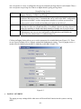
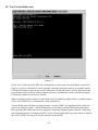
1
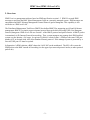
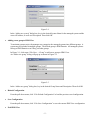
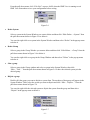
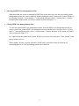
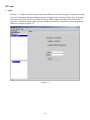
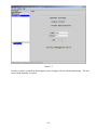
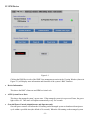
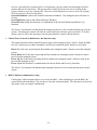
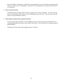
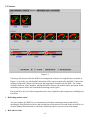
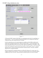
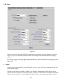
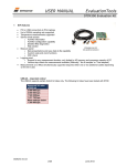
IPMI View User Guide
Copyright © 2002 Super Micro Computer, Inc., All rights reserved.
IPMI View (IPMI 1.5 Over LAN)
I. Overview:
IPMI View is a management software based on IPMI specification version 1.5. IPMI View sends IPMI
messages to and from the BMC (Base Management Card) on a remotely managed system. IPMI messages are
encapsulated in RMCP (Remote Management Control Protocol) packet datagrams. This capability is also
referred to as “IPMI over LAN”.
The Distributed Management Task Force (DMTF) has defined RMCP for supporting pre-OS and OS-absent
management. RMCP is a simple request-response protocol that can be delivered using UDP (User Datagram
Protocol) datagrams. IPMI-over-LAN uses version 1 of the RMCP protocol and packet format. A RMCP packet
is transmitted via IP (Internet Protocol) networking. Thus, system managers may manage their IPMI-enabled
system over the Internet. (Of course, in a private LAN this is a basic feature.) IPMI uses the same UDP port
number (623 in decimal) with ASF (Alert Standard Forum) protocol. If the managed system is protected by a
firewall, UDP port 623 must be opened.
In Supermicro’s IPMI solution, a BMC shares the LAN1 NIC on the mainboard. The NIC will re-route the
IPMI packet to the BMC instead of forwarding it to the upper layer network protocol stacks (as other protocol
packets do).
-2-
II. System Management:
Figure 2-1
As shown in Figure 2-1, there are several components in the IPMI View window (Figure 2-2):
1) Menu Bar: contains functions allowing you to add/delete systems or groups and save configurations.
2) System Window: lists managed computers with a BMC card.
3) Group Window: lists managed computers groups for more convenient management.
4) Viewing Window: shows detailed information, including Login, IPMI Device, Event Log, Sensors,
BMC Setting and Text Console.
5) Status Area: shows messages regarding current status.
6) Viewing System: IPMI View may manage up to 20 systems at the same time. The current managed
system is indicated in the Viewing System window.
-3-
Figure 2-2
•
Adding a new system to IPMI View
Figure 2-3
In Figure 2-3, click “File>New…>System” to add a new system to IPMI View. An “Add a new
system…” dialog box will pop up as shown in Figure 2-4.
-4-
Figure 2-4
In the “Add a new system” dialog box, key in the desired System Name for the managed system and the
correct IP address, as well as a Description. Then click OK.
•
Adding a new group to IPMI View
To maintain systems easier, the manager may categorize the managed systems into different groups. A
system may be included in multiple groups. The default group is IPMI Domain. All managed systems
belong to IPMI Domain even if they join other groups.
In Figure 2-1, click menu “File>New…>Group” to add a new group to IPMI View.
An “Add a new group” dialog will pop up as shown in Figure 2-5.
Figure 2-5
In the “Add a new group” dialog box, key in the desired Group Name and Description. Then click OK.
•
Reload Configuration
From the pull-down menu, click “File>Reload Configuration” to load the previous saved configuration.
•
Save Configuration
From the pull-down menu, click “File>Save Configuration” to save the current IPMI View configuration.
•
Exit IPMI View
-5-
From the pull-down menu, click “File>Exit” or press Alt-F4 when the IPMI View is running to exit
IPMI View. Remember to save your configuration before exiting.
Figure 2-6
•
Delete System
Select a system in the System Window you want to delete and then click “Edit>Delete…>System” from
the pull-down menu shown in Figure 2-6 to delete it.
You can also right click on a system in the System Window and then select “Delete” in the pop-up menu
to delete it.
•
Delete Group
Select a group in the Group Window you want to delete and then click “Edit>Delete…>Group” from the
pull-down menu shown in Figure 2-6 to delete it.
You can also right click on a group in the Group Window and then select ”Delete” in the pop-up menu
to delete it.
•
Join a group
Select a group in the Group window and select a system in the System Window, then click
“Edit>…Join…” from the pull-down menu shown in Figure 2-6 to have the selected system join the
desired group.
•
Disjoin a group
Double click the group you want to disjoin a system from. The members of that group will appear in the
System Window. Then, select the system you want to disjoin and click “Edit>…Disjoin…” from the
pull-down menu shown in Figure 2-6.
You can also right click the selected system to disjoin the system from the group and then select
“Disjoin” in the pop-up menu to delete it.
Figure 2-7
-6-
•
Selecting an IPMI View management session
When more than one system is managed by IPMI View at the same time, you can select which opened
management session you want to control by double clicking on system’s name in the System Window or
by selecting “Session><<System name>>” in the pull-down menu, where <<System name>> denotes
the name of the target system you want to control (as shown in Figure 2-7).
•
Closing IPIM View management session
To close the opened IPMI View management session, select the IPMI View management session you
want to close as the current IPMI View management session and then click “Session>Close <<System
name>>” in the pull-down menu, where <<System name>> denotes the name of the system you want to
close (as shown in Figure 2-7).
Or - right click on the system in the System Window you want to close and select “Close Session” in the
pop-up menu to close it.
When closing a session, a session will not be closed until 1) replies have been received for all
outstanding packets or 2) all outstanding packets have timed out.
-7-
III. Login
•
Login
In Figure 3-1, double click the system in the System Window you want to manage. A login screen along
with some information about the managed system will appear in the Viewing Window. Key in the login
ID and password and click the Login button to log in. When a login is successful, the Login button is
grayed (i.e., disabled) and the Logout button is enabled as well as the availability of other management
functions, as shown in Figure 3-2.
Figure 3-1
-8-
Figure 3-2
The default Login IDs are “ADMIN” and “USER”, which have the default passwords “ADMIN” and
“USER” respectively. Both Login ID and Password are case-sensitive.
In the IPMI design, an MD5 algorithm will encrypt the password when it’s transmitted through the
network. Once the password is confirmed, IPMI View will receive a “reply without error”. If the
password is invalid, after a short delay it will show a message in the Status Area that reads “Unable to
activate a session, please check ID and Password” (see Figure 3-3).
-9-
Figure 3-3
In order to reduce overhead on the managed system, all pages will not refresh automatically. The user
must refresh manually as needed.
- 10 -
IV. IPM Device
Figure 4-1
Clicking the IPMI Device tab of the IPMI View management session in the Viewing Window (shown in
Figure 4-1) will display some information and functions of the system’s BMC firmware.
•
Device Information
This shows the BMC’s firmware and IPMI revision levels.
•
ACPI System Power State
This shows the managed system’s power state. If the managed system is in a power-off state, the green
light will be off. This status will update automatically every five seconds.
•
Graceful Power Control (Administrator and Operator only)
Graceful power control will inform the OS running on the managed system to shutdown/reboot/powercycle within a specified time (the default is 30 seconds). When the OS running on the managed system
- 11 -
receives a graceful power control request, it will generate a pop-up window on the managed system’s
monitor and start to count down. This pop-up notice window gives the user who is working on the
system a chance to save any working files. However, remote login users or service users (for example
Web site visitors) will not see this notice.
Graceful Shutdown: same as the shutdown function in Windows. The managed system will enter an
S5 state.
Graceful Reboot: same as the reboot function in Windows.
Graceful Power Cycle: this function is a combination of the Graceful Shutdown and Power Up
functions.
The Power Cycle function will shut down the managed system for a few seconds and then power up the
system. Graceful power control will send an event to the System Event Log (next section). If no more
memory space is left for the incoming event, the graceful power control will not function.
•
Chassis Power Control (Administrator and Operator only)
The regular function forcibly controls the power state of the managed system’s chassis. When the BMC
receives a chassis power control command, it will directly control the power button or reset button.
Reset: this is the same as pressing the Reset button on a managed system’s chassis to reset the managed
system.
Power Down: this is the same as pressing the Power button on a managed system’s chassis to remove
power from the managed system.
Power Up: this is the same as pressing the Power button on a managed system’s chassis to turn on the
power of the managed system.
Power Cycle: this function is a combination of the Power Down and Power Up functions.
The Power Cycle function will shutdown the managed system for a few seconds and then power up the
system.
•
BMC Cold Reset (Administrator only)
Clicking the Cold Reset button allows you to reset the BMC. After confirming to reset the BMC, the
session will break immediately. The user has to close this session manually. This function is rarely used,
only in the event you suspect a malfunction.
- 12 -
V. System Event Log
Figure 5-1
Clicking on the Event Log tab of the IPMI View management session in the Viewing Window (shown
in Figure 5-1) gives you detailed information on the System Event Log for the BMC. It shows the
System Event Log version, number of log entries, free space for the System Event Log and the time of
recently added and recently erased System Event Logs.
•
Get System Event Log
In the Get Entries group on the upper left side of the Event Log tab in the Viewing Window, you can
decide how many logs you want to get from the BMC. Click the From button and keying in the first and
last numbers of the logs you wish to view or click the All button to get all the logs from the BMC. The
logs retrieved from the BMC will listed as a table in the central part of the Viewing Window. Please
refer to the IPMI specifications version 1.5 for detailed descriptions of each field. Some helpful fields:
Timestamp: the time the event happened.
Sensor Type: this could be health sensors or a system event.
Event Type: the event description.
- 13 -
Because the BMC communicates with the NIC on the mainboard via a slow channel, requesting only the
events you need to see is recommended. Choosing "all" to get hundreds of event entries will result in a
very long delay.
•
Clear System Event Log
Clicking the Clear All Entries button clears the logged system events on the BMC. The total event log
space is 16 KB. When all this space is used, any incoming event will be lost. The user has to clear the
system event log manually as needed.
•
Time stamp of System Event Log and Time Zone
To set the time stamp of the BMC on the managed system, key in the time in the Current SEL Device
Timestamp field and select the time zone in the Time Zone list. Then click the Set Timestamp button to
update the BMC.
Timestamp and Time Zone is the managed system’s local time.
- 14 -
VI. Sensors
Figure 6-1
Clicking on the Sensors tab of the IPMI View management session in Viewing Window (as shown in
Figure 6-1) provides you with detailed information of the sensors monitored by the BMC. It shows the
reading of supported voltages and fan speeds and temperatures monitored by the BMC. The current
reading is shown in yellow numbers, the high limits/low limits in red numbers and a description for the
monitoring sensors in blue text beneath the monitoring sensor figures.
Fan speeds have only a low limit, temperatures have only a high limit, and voltages have both high and
low limits.
•
Refreshing monitor status
You can configure the IPMI View to automatically refresh the monitoring status periodically by
checking the Auto Refresh check box and selecting the refresh period in seconds in the seconds list. Or,
click the Manual Refresh button to refresh the monitoring status every time you need an update.
•
Hide inactive item
- 15 -
IPMI View gets predefined sensor information from the mainboard. Some items may be not installed
for different configurations. For example, there will be no CPU fan if using a passive CPU heat sink,
and only one CPU on a dual CPU mainboard. The first time the sensors page is shown, IPMI View will
hide inactive items (default setting) if any. A manager may change this option later by unchecking the
“Hide inactive item” box, as shown in Figure 6-2.
Figure 6-2
- 16 -
VII. BMC Setting (Administrator only)
Figure 7-1
Clicking on the BMC Setting tab of the IPMI View management session in the Viewing Window (as
shown in Figure 7-1) gives you detailed information on the BMC LAN Configuration, SNMP trap
configuration and serial communication port of the BMC.
In order to support the power-down state management capability under the IPMI specification, the
manager has to configure the proper MAC address for each IP address. To deliver an IP packet to a
receiver, the sender needs to know the receiver’s MAC address or the gateway’s MAC address. ARP
(Address Resolution Protocol) is used to get the MAC address from the IP address. While the managed
system’s OS is running, the network protocol stack will take care this function. However, when the
managed system is in a power down state, this function cannot be achieved. Therefore, each MAC
address has to be configured manually.
BMC and running OS on managed system may use different IP Addresses for security reason. For
example, running OS may use 66.201.4.73 that can be reached by public access, while the IP Address
for BMC may be set to 192.168.1.55 that can only be reached in a private LAN. But, LAN MAC
- 17 -
address must be the same absolutely. If BMC uses a private IP Address, you have to make sure that the
manager’s system can communicate with the private IP Address for BMC on managed system.
•
BMC LAN Configuration
This shows the IP Address, LAN MAC, Gateway IP, Gateway MAC and Subnet Mask of the BMC and
allows you to modify them. NOTE: please make sure the MAC address of the LAN and gateway for the
BMC are correct before updating it by clicking the Update button. Be careful to enter the correct value,
especially for the LAN MAC. If you enter the wrong LAN MAC, IPMI View cannot connect to that
system any more.
If you accidentally enter a wrong LAN MAC value, you may use the IPnMAC command in the IPMI
Solution/Utility subfolder on this CD to update it. IPnMAC, which is a DOS command, must be
executed on the managed system.
•
SNMP
This shows the SNMP trap configuration of the system needing to receive the SNMP traps generated by
the BMC and allows you to modify them. To change the configuration on the BMC, key in the SNMP
community name in the Community text filed and the IP Address and MAC Address in the SNMP Trap
Receivers table in the SNMP group, and then click the Update button.
When any critical error occurs, an SNMP trap packet will be sent to all receivers in the list. To remove
an SNMP receiver, you may change both IP and MAC addresses to 0.0.0.0 and 00:00:00:00:00:00
respectively, and then click Update.
On the system receiving the SNMP traps, a SNMP trap receiver software need to be installed and run up.
The managed system will send out SNMP trap packet to receivers at the moment event occurs. If
SNMP trap receiver is not running up, the trap packet is discarded and won’t be queued at anywhere.
•
RS232 / MODEM
This shows the configuration of the RS232 interface on the BMC. It is used to initialize the RS232 port
and the installed modem, if any. The RS232 port is the box-header (Figure 7-2) on the BMC and is a
dedicated serial port.
Baud Rate: the baud rate for serial connections (does not affect paging settings).
Modem Init String: the modem initialization string for serial connections (does not affect paging
settings).
Figure 7-2
- 18 -
VIII. Users
Figure 8-1
Clicking on the Users tab of the IPMI View management session in the Viewing Window (as shown in
Figure 8-1) gives you detailed information on the Users management, and the thresholds for paging
severity.
We strongly suggest you change passwords immediately to prevent malicious users getting control
before you.
•
USERS
There are some buttons that allow you to add/delete a user, set user’s privileges, change passwords and
enable/disable paging.
There are six privilege level groups, Callback, User, Operator, Administrator, OEM, and No Access.
Only the first four privilege levels are implemented. Privilege Levels determine which IPMI commands
a given user can execute over a given channel. Privilege Limits set the maximum privilege level that a
- 19 -
user can operate at. A user is configured with a given maximum privilege limit for each channel. Thus, a
user can operate at a privilege level that is no higher than his group privilege limit.
Callback
User
Operator
Administrator
Group Privilege Levels
This may be considered the lowest privilege level. Only commands necessary to
support initiating a Callback are allowed.
Only ‘benign’ commands are allowed. These are primarily commands that read data
structures and retrieve status. Commands that can be used to alter BMC configuration,
write data to the BMC or other management controllers or perform system actions
such as resets, power on/off, and watchdog activation are not allowed.
All BMC commands are allowed, except for configuration commands that can change
the behavior of the out-of-band interfaces. For example, Operator privilege does not
allow the capability to disable individual channels or change user access privileges.
All BMC commands are allowed, including configuration commands. An
Administrator can even execute configuration commands that would disable the
channel that the Administrator is communicating over.
Clicking on Paging Setting allows you to set the parameters for an individual user (Figure 8-2). There
are two types of paging service: Numeric paging and Alphanumeric paging. To use a paging service, a
modem must be connected to the RS232 connector on the BMC (Figure 7-2).
Figure 8-2
•
PAGING / SEVERITY
The paging severity settings define when users will be notified of entries into the system event log
(SEL).
- 20 -
The following settings are available for each group:
None
When this is selected, user notification for this group is inactive.
Warning
When this is selected, the RMC will notify users when SEL entries for the group
exceed the warning thresholds.
When this is selected, the RMC will notify users when SEL entries for the group
exceed the critical thresholds.
When this is selected, the RMC will notify users of all SEL entries of events for the
group.
Critical
All
All warning and critical thresholds are predefined by Supermicro and based on hardware design.
- 21 -
IX. Text Console Redirection
Figure 9-1
On the Text Console tab of the IPMI View management session in the Viewing Window (as shown in
Figure 9-1), there is a function for you to remotely control the managed system in a text mode console.
Click the Start button to start the text console redirection. During the control, click the ReSynch button
to synchronize the text console with the managed system if you think the screen is not shown properly.
Click the Stop button to stop the text console.
When a managed system switches its video mode from Text Mode to Graphics Mode, a terminate notice
will be sent to IPMI View to terminate the console redirection.
Console Redirection will dump a managed system’s screen to IPMI View and send the key codes you
press to the managed system. Console Redirection is not a function in the IPMI specification, Super
Micro provides this useful function for a manager to control the managed system remotely. Especially,
when managed system is booting up in POST, no any software application can get the control to redirect
the console, IPMI View may give you this function of great ability.
- 22 -
Important: Console Redirection puts a very heavy load on a managed system. It will dump the whole
screen to the manager’s system and slow down the managed system significantly. We suggest you use
this function only when you need to get special control and cannot achieve it any other way. For other
applications, a proper console redirection software (pcAnywhere, Symantec Corporation) or a remote
login protocol (telnet) is suggested. When you finish your remote operation, click Stop to terminate
console redirection to take the load off the managed system.
- 23 -