1
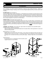
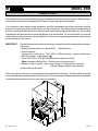
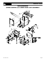
MODEL #500 OWNERS MANUAL
50 YEARS OF QUALITY AND SERVICE
Made in the U.S.A.
KRENDL MACHINE COMPANY • 1201 SPENCERVILLE AVE
DELPHOS, OHIO 45833 • TELEPHONE 419-692-3060 • FAX 419-695-9301
E - MAIL: [email protected] • WEB SITE: www.krendlmachine.com
CONGRATULATIONS ON YOUR PURCHASE OF KRENDL EQUIPMENT
THIS IS YOUR
MODEL #500 OWNER'S MANUAL
FOR ASSURED SAFETY AND CONFIDENCE, PLEASE READ THIS
MANUAL CAREFULLY BEFORE OPERATING YOUR MACHINE.
THANK YOU FOR YOUR PURCHASE!
KRENDL E-MAIL ADDRESS IS: [email protected]
KRENDL WEB SITE IS: www.krendlmachine.com
Table of Contents
PAGE
INTRODUCTION . . . . . . . . . . . . . . . . . . . . . . . . . . . . . . . .
1
GENERAL SAFETY INFORMATION . . . . . . . . . . . . . . . . .
2-3
RETURNED GOODS PROCEDURE . . . . . . . . . . . . . . . . .
4
WARRANTY . . . . . . . . . . . . . . . . . . . . . . . . . . . . . . . . . . . .
5
ASSEMBLY . . . . . . . . . . . . . . . . . . . . . . . . . . . . . . . . . . . .
6
BASIC COMPONENTS . . . . . . . . . . . . . . . . . . . . . . . . . . .
7
THEORY OF OPERATION . . . . . . . . . . . . . . . . . . . . . . . .
8
OPERATING INSTRUCTIONS
Machine Hook-up . . . . . . . . . . . . . . . . . . . . . . . . . . . . 8-9
Electrical Operation . . . . . . . . . . . . . . . . . . . . . . . . . . 10
Mechanical Settings . . . . . . . . . . . . . . . . . . . . . . . . . . 11-12
GENERAL MAINTENANCE . . . . . . . . . . . . . . . . . . . . . . . . 12-16
ELECTRICAL SYSTEM . . . . . . . . . . . . . . . . . . . . . . . . . . . 17-21
TROUBLESHOOTING . . . . . . . . . . . . . . . . . . . . . . . . . . . . 22-24
PARTS LIST. . . . . . . . . . . . . . . . . . . . . . . . . . . . . . . . . . . . 25-40
GLOSSARY. . . . . . . . . . . . . . . . . . . . . . . . . . . . . . . . . . . .
41
SERVICE RECORD. . . . . . . . . . . . . . . . . . . . . . . . . . . . . .
42
MODEL #500
INTRODUCTION
Thank you for purchasing a KRENDL FIBER MOVING MACHINE. With over fifty years experience in
manufacturing fiber moving equipment, we have designed and built your machine with the highest quality
to provide years of reliable service.
This manual has been prepared to help you obtain the maximum efficiency and service from your Krendl
equipment. The machine is designed to condition and apply fibers with the utmost in dependable
performance. Our primary objective is to build equipment which will provide complete satisfaction so that
you may confidently recommend Krendl to others.
We do not manufacture or sell fibers. Our interest lies only in the proper performance of the equipment we
manufacture. We make no recommendations or guarantees concerning various fibers.
CAUTION:
This manual contains important information regarding the safe assembly and operation of your
machine. We urge you to read it carefully and follow the instructions provided. If your questions are not
answered in this manual, may we hear from you? We want you to be able to operate this unit safely
and confidently.
UNPACKING: Store and unpack carton with correct side up. Unpack your machine IMMEDIATELY and
check for damage in shipping. Place any damage claim with delivering carrier, saving all packing
materials for inspection. Our warranty covers manufacturer's defects only. DO NOT return to shipper.
FILL IN AND RETAIN:
Krendl Machine Company
1201 Spencerville Ave.
Delphos, Ohio 45833 U.S.A.
Telephone:
Fax:
E-mail:
Web Site:
419-692-3060
419-695-9301
[email protected]
www.krendlmachine.com
For your protection in the event of theft or loss, please fill in the information requested for your own
records. This information will be needed for in-warranty repairs. You may also want to attach a copy of
your invoice.
Machine model number
Serial number
Blower(s) serial number(s)
Date of purchase
_
_
_
_
Blower motor manufacturer
_
Agitator motor manufacturer
_
Speed reducer manufacturer
_
Supplier
_
The model and machine serial numbers are located on the base of the machine unit. The blower(s) serial
number(s) is located on the motor housing of blower.
Rev. Date: 1/18/10
Page 1
MODEL #500
GENERAL SAFETY INFORMATION
Important: Read all instructions before operating this unit. This equipment can be potentially
dangerous and must be used in strict accordance with instructions.
Disclaimer Notice: The manufacturer will not be legally responsible for any injury or damage resulting
from the improper use of this equipment or the failure to follow instructions.
Unpacking
Handle cartons with care to avoid damage from dropping or bumping. Store and unpack cartons with the
correct side up. Completely remove machine from the packaging and from any shipping pallet or skid to
which it might be attached. In addition, completely remove all shipping materials from inside the machine.
General Safety
1. Read this manual carefully and become familiar with your machine unit. Know its applications,
limitations, and any hazards involved.
2. This machine was designed and manufactured for specific applications. Do not attempt to
modify the unit or use it for any application it was not designed for. If you have any questions
about your intended use or the machines suitability, ask your dealer/distributor or consult the
factory. The manufacturers' could not possibly anticipate every circumstance that might involve
a hazard. For that reason, warnings in the manual and warning tags or decals affixed to the unit,
are not all-inclusive. If you intend to handle, operate, or service the unit by a procedure or method
not specifically recommended by the manufacturer, first make sure that such a procedure or
method will not render this equipment unsafe or pose a threat to you and others.
Electrical Safety
• The National Electric Code (NEC) in the United States and many international electrical codes require
frame and external electrically conductive parts of this machine to be properly connected to an approved
earth ground. Local electrical codes may also require proper grounding of machine. Consult with local
electricians for grounding requirements in your area.
• Never handle any kind of electrical cord or device while standing in water, while barefoot or while hands
or feet are wet. Dangerous electrical shock will result.
• Use a ground fault circuit interrupter (GFCI) in any damp or highly conductive area. (metal decking or steel work)
• Reference NFPA 79, 70E, or OSHA safe work practices when performing energized work procedures.
Rev. Date: 1/18/10
Page 2
MODEL #500
Safety/Caution
• Be Safe - Keep away from moving parts.
• Be Safe - Make sure all guards, hopper bars, and hopper extensions are in proper place before
operating machine. Hands should never pass below hopper bars.
• Be Safe - Do not remove motors or lift hopper when unit is connected to power supply.
• Be Safe - Make sure blower motor control and remote control hand pendant switch are in off position
before connecting the power supply to the machine.
• Be Safe - Make sure machine is properly grounded. Protect all electrical supply cords from sharp
objects, moisture, and other potentially hazardous materials. Keep power cords in good
repair. Electrical service must be performed by a qualified electrician.
• Be Safe - Disconnect power supply before inspecting or adjusting unit.
• Be Safe - Consult a qualified technician to answer questions before attempting to operate, or injury may
result.
• Be Safe - Wear an approved dust mask or respirator for operator comfort and protection.
• Be Safe - Emergency Kill Switch - In case of emergencies, always use red stop button located on top
of Main Control Panel. It will stop all feeding and agitation.
Make Sure!
• Hopper is empty of foreign objects before starting.
• Adequate electrical power is supplied or damage to unit will result.
• Blower filter is kept clean and in place when blower is on.
• Blower is turned off immediately if hose is plugged, or blower will overheat.
• Agitator motor must be on before adding fiber.
• Blower(s) must be on, when agitators are running, or machine will bind.
• Agitator motor is not run with hopper empty for more than a few minutes, or damage to seals will result.
• Sprockets, chains, belts and pulleys are correctly aligned and tensioned.
• Pieces of bag are not left in the machine as this can bind and stall your machine.
Rev. Date: 1/18/10
Page 3
MODEL #500
RETURNED GOODS PROCEDURE:
When returning products to Krendl for repair, first obtain a return goods authorization, and you will be given
shipping instructions. The product must be shipped PREPAID:
Krendl Machine Company
1201 Spencerville Ave.
Delphos, Ohio 45833 U.S.A.
Telephone: 419-692-3060
Fax:
419-695-9301
E-mail:
[email protected]
Web Site: www.krendlmachine.com
IF MACHINE WAS NOT PURCHASED DIRECTLY FROM KRENDL MACHINE COMPANY, CONTACT YOUR SUPPLIER.
Once unit is received, it will be inspected. In-warranty units will be repaired and returned immediately.
Estimates of repair charges will be provided for out-of-warranty units.
Rev. Date: 1/18/10
Page 4
MODEL #500
WARRANTY:
Krendl Machine Company (Company) warrants to each original purchaser (Buyer) of its
equipment or accessories that such products will be free of manufacturing defects for a period
of 12 months from the date of shipment to the Buyer.
No warranty is made with respect to:
1. Components or accessories manufactured and warranted by others. Warranties for
purchased component parts as supplied from vendor such as engine, electric motor,
blower, gearbox, transmission, etc., if furnished by the manufacturer of the component, are
on file at the Company’s main office and copies will be furnished at request of Buyer.
Component(s), shipping costs prepaid, shall be sent to Company who in turn shall forward
to vendor for evaluation and warranty determination.
2. Any defect caused by repair, alteration and/or adjustment performed by Buyer or customer/
vendor of Buyer without the express written authorization of the Company.
3. The labor costs of replacing parts by parties other than the Company.
4. Any machine that has not been operated and/or maintained in accordance with normal
industry practice and the written recommendations of the Company. (e.g. machine operated with an improperly sized, worn or damaged hose, improper or inattention to preventative maintenance, etc.)
5. The product has been subjected to misuse, negligence or accident or results of any
application or use of the blowing equipment not in accordance with the Company recommendations.
This limited warranty does not cover the free replacement of component parts that become
inoperative due to wear and usage and need to be replaced on a regular basis, including but not
limited to: airlock seal(s), agitator(s), shredder(s), auger(s), fuse(s), switch(es), clutch(es), hose(s),
shaft seal(s), chain(s), belt(s), sprocket(s), pulley(s), bearing(s), cable(s), battery(ies), filter(s),
fan(s), etc.
The Company’s obligation under this warranty is limited to repairing or replacing (at Company
option) any part that is determined by the Company to be suffering from a manufacturing defect.
The Company (at Company option) will provide any required parts and labor to the Buyer. If the
equipment or parts must be returned to the Company for repair, all transportation costs shall be
the Buyer’s responsibility.
This limited warranty is expressly in lieu of any other guarantees and / or warranties, oral or
written, expressed or implied, including without limitation, the implied warranty of merchantability. No warranty, express or implied, other than the aforesaid warranty is made or authorized by
Company. Company shall not be liable for any direct, indirect, incidental or consequential
damages to property or injury to any person or costs associated with loss of production resulting
in loss of revenue, profits or loss of equipment through the use of this equipment.
Note: Special job circumstances incurring costs for specialized repair and next day delivery
of parts will not be reimbursed by the manufacturer unless authorized by factory.
Rev. Date: 1/18/10
Page 5
MODEL #500
ASSEMBLY
Prior to packing, your machine has been assembled and tested to assure quality performance. However, to
safeguard against damage in shipping, certain items are packaged separately within your carton and will need
assembly.
BLOWER DOOR: (See illustration A)
This unit has Blower Door and Filter inside hopper. Install the Blower Door and Filter on machine and secure with
Filter Clips. (Blower Filter must remain in Blower Door.) An appropriate size hose is attached to the blower door
input tube and the other end is located elsewhere to provide clean air to blowers. A fine screen, acting as a filter,
over end of hose eliminates accumulation of unwanted debris. This eliminates frequent cleaning of the blower
filter. (Frequent inspection of input hose is recommended.)
POWER CORDS: (20-30 amp twist lock inputs only)
Female receptacle(s) need to be wired properly to main power cord(s). (For 240 volt 60 hz. see illustration F and
consult electrician for assistance.) Units shipped to European countries will have standard (2) two prong 230V
16 amp plugs supplied. Units shipped overseas to other than Europe do not have plugs and receptacles on input
cords due to the varying electrical plug configurations in different countries, unless provided by Krendl agents or
suppliers.
ASSEMBLY OF OPTIONS: (See illustration B) Options below are available on the model #500 machine.
5" Wheel Package: (standard or heavy duty)
Attach two swivel casters on airlock end of machine for increased mobility. Mount rigid casters on control end
with the hex bolts provided.
Bushing Reducer: (2 1/2" output)
Bushing reducer inserts into output tube of airlock. Press reducer firmly against shoulder and tighten two
hold-down bolts to secure unit in place. The bushing reduces the size of opening to hose at its source,
providing a more consistent feed while preventing hose plugs. (Standard output tube on model #500 is
3".)
Hopper Extension:
If Hopper Extension is not shipped mounted on machine, place
Hopper Extension on top of machine.
(illustration A)
Rev. Date: 1/18/10
(illustration B)
Page 6
MODEL #500
BASIC COMPONENTS
This is a view of the basic components of your machine. It shows the location of each item and gives the
function of each. Use this as a guide throughout the manual.
(illustration C)
A) BASE UNIT—Lower frame unit supporting
blower box, speed reducer, motor, airlock
and hopper.
B) AIRLOCK—Traps air and fiber while providing a metered flow.
C) SLIDEGATE—Meters the amount of fiber
dropping into the airlock by controlling size of
airlock opening.
D) SPEED REDUCER—Increases output
power while decreasing speed of agitator/
airlock drive motor.
E) BLOWER BOX—Enclosure protecting highpressure blowers from contamination.
(illustration C)
F) MOTOR—Provides driving power for speed
reducer and agitator/airlock system.
G) AGITATOR—Conditions fiber in the hopper.
H) HOPPER—Upper unit of machine holding
fiber.
I) MAIN CONTROL PANEL—Connects with
main power, allowing operation of unit at
machine or Remote Cord.
J) REMOTE CORD HANGER—Storage for
remote control cord.
K) KILL SWITCH—Safety device for immediate stopping of machine.
(illustration D)
L) SHREDDER SYSTEM (optional)—
Increases production and coverage on all
fiber products while reducing clumps that
may exist in various fibers.
M) HOPPER EXTENSION (optional)—
Increases overall hopper capacity.
Rev. Date: 1/18/10
(illustration D)
Page 7
MODEL #500
THEORY OF OPERATION
This unit is designed to accept all fiber materials into the
hopper area of the machine, passing through a multistep
agitation system and dropping into the rotating airlock
feeder. The airlock feeder has a crankgate control providing
precision feeding of fiber for open blowing, sidewall blowing,
and spray-on applications. Fiber is then rotated to a 6:00
o'clock position where air from the blower motor pushes fiber
from the rotating chambers through the hose. Material and
air is prevented from escaping into the machine while in the
airlock by six rubber seals which conform to the airlock inner
wall as the chambers revolve. The blower motor is either a
two or three stage, high r.p.m. unit with low amperage
designed to blow air. (Fiber does not pass through the
blower fan chamber.) The high pressure and adjustable
volume provides low amperage, low noise, and minimal attic
dust. This reduces hose plugging problems and gives
longer blower life.
Note: All Fiber/airlock machines provide slightly less coverage than thru-blower machines. Airlock machines cannot
duplicate the high speed (13,000 r.p.m.) conditioning effect
of fiber passing through the blower. These units blow the
fiber closer to settled density which eliminates the need for
overblowing material to compensate for progressive settling.
OPERATING INSTRUCTIONS: MODEL #500
Machine Hook-up
This unit comes ready for connection to insulation hose, power cords, and accessories.
This unit provides a direct connection to 3" insulation hose. Slide hose on to outlet and secure with a hose clamp. All hose
connections must have hose clamps to prevent air leakage from blower to nozzle. This helps to prevent hose plugging.
Remove remote control cord, blower door, packet, accessories,ect. from hopper and plug remote control cord into Main
Control Panel located on hopper. (See illustration E)
The first bag of insulation into hopper should be well broken by hand to assist agitator action. Caution: Hopper bars must
be in place while loading hopper. Never put hands below bars or force feed fiber by pushing down on insulation.
When assembling unit, make sure remote control hand pendant switch is in the off (middle) position and close slidegate.
1. Connect power to Input Cord(s) located below Main Control Panel. (See illustration E)
On double input units, both input cords must be supplied with power from two separate sources for unit to work properly.
When using extension power cords, wire gauge size should not be less than input cord on unit and not to exceed 50' in
length. Caution: Operating unit with less than required voltage or inadequate generator size will result in damage to
electrical components. This machine is marked with the correct input voltage on input cords located on bottom of the
Main Control Panel. Do not operate machine with less than required voltage. Damage to motors and other electrical
parts will result. Check voltmeter on Main Control Panel when machine is running.
2. For 240volt, 60hz. models only, properly connect female receptacle to extension cord. See illustration F and consult
electrician for assistance.
Rev. Date: 1/18/10
Page 8
MODEL #500
Machine Hook-up (cont.)
(illustration E)
Electrical Hook-up for 240volt, 60hz.
(illustration F)
IMPORTANT NOTE FOR 3-WIRE CORD:
A separate isolated ground is required that connects the frame of the machine to an earth ground
source. Serious injury or death may result if machine is not properly grounded. If you have any
further questions, consult a qualified electrician.
Rev. Date: 1/18/10
Page 9
MODEL #500
Electrical Operation
PRESS KILL SWITCH TO IMMEDIATELY STOP MACHINE AT ANY TIME!
1.
2.
3.
4.
Make sure Kill Switch is out by pulling. (See illustration G)
Turn red Main Disconnect Switch to ON position. (See illustration G)
Set 4-Position Selector Switch to OFF. (See illustration G)
Press green start Button. Machine will not run unless start button is pressed after Kill Switch is out and red Main
Disconnect Switch is on. (See illustration G)
5. Select operating mode on 4-Position Selector Switch from one of the following options:
Remote:
Off:
Blower:
Agitator-Feed/Blower:
Remote control hand pendant will control machine.
Machine will not run. (overrides remote hand pendant)
Only the blower will run continuously. (manual control at machine)
Both the blower and the agitator-feed will run continuously. (manual control at machine)
Main Control Panel (lid closed)
(illustration G)
6. When operating in Remote mode, the 4-Position Selector Switch must be set to Remote position. (See illustration G)
7. Remote control hand pendant positions will be selected from the following:
BLOWER-FEED - operates both blower motor and agitator-feed motor simultaneously
OFF
- (middle position) all functions stop
BLOWER
- operates the blower motor only
(illustration H)
8. If using optional Internal Wetting System(IWS), connect IWS cord to 24 VAC Outlet on Main Control Panel.
9. Adjust blower(s) and slidegate to desired settings. (See page 11)
10. To adjust alarm time, follow the procedure below: (See illustration I)
Main Control Panel (lid open)
a) Unplug machine from power source.
b) Turn off red Main Disconnect Switch, loosen two screws in door,
and open Main Control Panel lid.
c) Turn Timer Relay knob to desired setting. (clockwise to increase
warning time)
d) Close lid, tighten two screws in door, plug in machine, turn on red
Main Disconnect Switch and press green Start Button.
e) Retest machine.
(illustration I)
Rev. Date: 1/18/10
Page 10
MODEL #500
Mechanical Settings
The control end of your machine contains blower and slidegate controls to adjust your machine for each application and type
of fiber. (See illustration J) Blower control (air) and slidegate (material feed) are adjusted according to:
APPLICATION:
TYPE OF MATERIAL:
Open blow, retro-sidewall and spray-on applications require varying amounts of control.
Cellulose, fiberglass, and mineral wool have different textures and densities that respond to
machine settings.
HOSE:
Corrugations or roughness of interior surface, diameter, length and elevation of hose will also
require varying adjustments.
WEATHER CONDITIONS: Temperature and humidity may require day to day adjustment of machine settings.
BLOWER CONTROL AND SLIDEGATE GENERAL SETTINGS:
Blower control can increase or decrease the amount of air in the
system, affecting the velocity(speed) and spread rate(coverage) of
fiber. (See illustration J) The blower control dial operates clockwise,
from HIGH to LOW, controlling air pressure and amount of air.
Opening or closing slidegate (material feed) controls the amount of
fiber dropping into the airlock which changes the production rate (lbs.
per hour). (See illustration J) For calibration purposes the scale
located on right side of machine indicates how many inches the
airlock slidegate is opened.
The blower and slidegate controls working together affect the
distance fiber can be blown through a hose without plugging. These
controls also affect the accurate blowing of fibers for spraying
applications.
These settings control the following:
• Density of fiber blown in retro-sidewall application.
• Velocity of material impact when spraying.
• Dust on open blow.
• Material spread rate or coverage.
• Production rate (lbs. per hour blown).
GENERAL BLOWER CONTROL AND
SLIDEGATE SETTINGS FOR OPEN BLOW:
(See illustration J)
With the slidegate closed, turn agitator-feed motor on and variable speed blower control(s) on low.
Fill hopper with insulation and adjust blower control and slidegate. In making adjustments, move
controls proportional to each other. (i.e. If variable
speed blower control is half speed, slidegate
should be half open.) Open slidegate to allow fiber
to drop into the airlock providing good production,
but not beyond point where hose plugs. As hose
length is increased, the blower control speed is
increased while closing the slidegate proportionally. This will increase the distance fiber can be
blown through the hose and improve material coverage rate, while decreasing the blowing production
rate (lbs. per hour blown). These adjustments are
for open blow. If specialty application or retro
sidewall work is done, refer to General Blower/
Slidegate Settings chart (below left) or fiber manufacturer.
Control End of Machine
GENERAL BLOWER/SLIDEGATE SETTINGS:
Since specific settings need to be determined by each operator, the
following are only suggested guidelines. Consult the fiber manufacturer
for additional recommendations specific to their product.
APPLICATION
Open Blow
Sidewall-Retrofit
Wall Cavity Spray
Commercial Spray(Adhesive)
BLOWER CONTROL SLIDEGATE
High
Full Open
High
Half Open
Medium
Half Open
High
One-third Open
(illustration J)
Rev. Date: 1/18/10
Page 11
MODEL #500
Mechanical Settings (cont.)
OPTIONAL SHREDDER ASSEMBLY:
If this unit is supplied with a shredder assembly; airlock/agitator speeds are preset at the factory. No further sprocket setting
speeds are needed, as this system will accommodate most fibers and applications. However, the shredder direction can be
adjusted as described below.
SHREDDER ADJUSTMENT:
Unidirectional Rotation (See illustration K) is preferred as an
all-around setting for a combination of materials and applications.
This setting provides for the greatest coverage and best control
of the fibers in wall cavity spray,
commercial spray, internal wetting (stabilized) and open blow
applications.
(illustration K)
Center-Down Rotation
(See illustration L) force
feeds the fiber into the
airlock at a faster rate.
This direction is preferred
for the greatest production of various fibers in an
open attic blow application
although coverage may decrease.
(illustration L)
GENERAL MAINTENANCE
Periodic preventive maintenance will add years of life to your equipment. Reviewing the information in this manual will go a
long way in reducing downtime and lost income. To Flip hopper up for easy maintenance of lower base unit: (See illustration
M) Remove side screen guard of machine. Loosen idler sprocket and remove drive chain. Release hold down bolts at airlock
end of machine and lift hopper back gently until it rests safely on the floor.
KEEP CLEAN: During operation, keep material from accumulating on Blower Filter. Always keep Filter in place while
operating machine. After each use, remove fiber from hopper and blow out hose. (Use BLOWER mode at Main Control
Panel or Hand Pendant.) Clean air from insulation hose can then be used to blow fiber from agitator motor and Blower
Filter area. The Blower Door attached to this unit reduces filter maintenance.
AIRLOCK:
SEAL REPLACEMENT: The purpose of the airlock seal is to trap air and fiber until
it rotates 180O to the 6:00 o'clock position. At this point, fiber is pushed by air from
the blower, out of the chamber. Worn or damaged seals allow air and fiber to
escape back into hopper, thus reducing production and coverage. When it is
necessary to replace seals, follow these directions:
Airlock rotor plates that are damaged (bent) will need replaced. (Refer to Rotor
Plate Replacement on next page.) Take out rubber seal by removing six plate
fastening bolts and top plate. The base plate will remain attached to airlock shaft.
To install a new seal, reverse procedure. Seal should be inserted tight against the
back base plate, pressing the lower tabs of seal down under the adjacent seal with
a flat blade screwdriver. (See illustration N-1) Make sure all bolt holes are aligned
while each side of seal is equally pressed against the end plates, before tightening
bolts. Seal should be bent backwards for counterclockwise rotation, viewing from
drive side of machine.
Rev. Date: 1/18/10
(illustration M)
Page 12
MODEL #500
General Maintenance (cont.)
ROTOR PLATE REPLACEMENT:
1.To check plates for proper angle, measure distance between outer edge of metal plates. (See illustration N-1) This
measurement should be 4 3/4". Measure all six plates and replace as needed.
2.Remove damaged baseplate assembly from shaft using ratchet drive wrench with extension and 1/2" socket.
3.Check seal for wear and damage. (Installing seal and top plate on the bench is quick and easy). Remove bolts from
plate assembly and replace with new seal. Make sure seal and top plate are assembled on correct side of base plate
before assembling in airlock. Seal should press backward towards top plate when installed correctly into airlock
chamber. (See illustration N-1)
4.Install the rotor plate assembly into the airlock. The airlock runs counterclockwise viewing it from the sprocket drive
shaft. (See illustration O) Align the base plate with holes on airlock shaft using a tapered punch. Caution: Do not
mount rotor plate backwards. If installed improperly, damage to seals will result and put undue stress on agitator motor.
This causes overheating and poor production. Seal should be bent backward to allow for a counterclockwise rotation
of rotor.
5. As rotor plate is installed, press bottom tab of seal under adjacent seal with flat blade screwdriver. (See illustration N-1)
(illustration N-1)
(illustration O)
(illustration N-2)
(Entire rotor plate assembly may be removed and replaced. This
procedure maybe easier than replacing just the seals.)
CHAIN: (#40 Nickel Plated)
ADJUSTMENT: A smooth operating chain drive should have a slight sag on the idler side of the chain. New chains should be
installed under slight tension as they will elongate a small amount due to seating of pins and bushings during the first few days
of operation. Excessive chain tension or loose chain will cause shortened life of bearings, chain and sprocket. Chain should
be kept in good condition by proper lubrication (dry film lubricant Dow 321) and occasional cleaning. Soaking chain in
container of 10 weight oil will provide for internal lubrication of pins and bushings. However, excess oil must be drained and
wiped away as excessive lubrication will cause fiber accumulation on chain. Worn out chain should be replaced. When chain
is replaced, worn sprockets should also be replaced, preventing further damage to new chain.
Rev. Date: 1/18/10
Page 13
MODEL #500
General Maintenance (cont.)
SPROCKETS:
CHECK SPROCKETS FOR WEAR. Misalignment and/or loose sprockets and improper chain tension causes the premature
wear of chain and sprockets. All sprockets, except speed reducer and idler sprockets, have been secured with a medium
grade Loctite (general purpose thread locker), to prevent gradual movement. The set screws and key are also inserted with a
medium grade Loctite. If sprocket is difficult to remove, it may be heated with a propane torch to loosen.
Caution: Do not overheat sprocket or damage to bearing will result. A pulley or bearing puller can then be used to
remove the sprocket and key. Replace new sprocket on shaft with key and medium grade Loctite applied to shaft.
Align sprocket with corresponding sprocket, using a straightedge placed along face of teeth and tighten set screw.
BEARINGS:
AGITATOR BEARINGS in hopper are prelubricated, double-sealed, self aligning ball bearings. No lubrication is necessary. If
bearings produce noise or heat (too-hot-to-touch), the bearings should be replaced.
AGITATOR BEARING REPLACEMENT: Spray area with rust penetrant (WD-40). Remove sprocket(See SPROCKET
section above). Remove the two bolts from bearing flange and outer flange from bearing insert. Loosen set screws on bearing
hub at each end of agitator shaft. Since all set screws are installed with a medium grade Locktite, a propane hand torch may
be used to assist in removing them. Do not overheat unit, causing shaft to expand. Using a rubber mallet, drive agitator shaft
an inch in one direction, creating a space between hopper and bearing unit. A bearing puller can then be used to remove the
bearing. Eliminate any metal burrs from shaft with file and install new bearings with felt seals. Use a medium grade Loctite
on set screws before securing bearing to shaft. (Check shaft diameter before ordering bearings; 3/4" or 1")
AIRLOCK AND SHREDDER BEARINGS are prelubricated, double sealed, self aligning ball bearings. Lubrication is required
at three month intervals of normal running time, or sooner if bearings produce a noise or become too-hot-to-touch.
Relubrication at the grease fittings is done with a lithium base grease conforming to a NLGI GRADE TWO consistency. The
grease should be pumped in slowly until a slight bead forms around the seals. This bead, in addition to acting as an indicator
of adequate lubrication, provides additional protection against the entry of foreign matter. Important: If a slight bead does not
form, indicating a failure of lubrication, or if bearing shows signs of wear, replace bearing.
AIRLOCK AND SHREDDER BEARING REPLACEMENT: Remove four bolts from airlock bearing flange (two bolts from
shredder bearing flange) and follow steps above for agitator bearing replacement.
SPEED REDUCER:
Periodically check oil level in reducer. Do not lay machine on its side as lubricant will drain from vent plug. If speed reducer
malfunctions because of improper oil level or type used, warranty is voided. Oil seals at input and output drives are
considered to be replaceable maintenance items and can affect oil level. These are available at power transmission suppliers.
LUBRICATION: This speed reducer was filled with oil at the factory to operate within +30OF to +125OF ambient temperature.
After 1500 hours of operation, drain and refill with Klubersynth UH1 6-460 gear oil. If Klubersynth UH1 6-460 gear oil is not
available, use multipurpose gear oil SAE #90 for ambient temperatures from +40OF to +120OF. For temperatures below +40OF
use SAE #80 multipurpose gear oil. Correct oil level for mounted unit is just below pipe plug (C on illustration P) in side
position.
LUBRICANT REPLACEMENT: (See illustration P)
(illustration P)
1. Drain: With output shaft of speed reducer facing you, remove plug
(A) lower front with 1/4" hex key wrench. Allow unit to completely
drain and replace plug.
2. Remove vent plug (B) on top of reducer, and plug (C) on left side.
3. Fill with recommended lubricant (use Mobilgear 630 gear oil)
through vent plug (B) opening, using a flexible funnel, until lubricant
exits the left side opening (C).
(Make sure speed reducer is
level when replacing lubricant.)
4. Replace vent plug (B) and left plug (C).
Rev. Date: 1/18/10
Page 14
MODEL #500
General Maintenance (cont.)
AGITATOR MOTOR:
If agitator motor runs hot, activating the manual reset on motor, or if unit does not run properly, refer to troubleshooting
sections of manual. The agitator motor should start quickly and run smoothly. If not, shut motor off immediately and check
the cause. Low voltage, incorrect power supply, or misconnected wiring could cause motor failure. These conditions void
the motor warranty. Overload conditions can be detected by checking the electrical current(amperage) compared with
nameplate current(amperage) located on the body of the motor.
AGITATOR MOTOR REPLACEMENT: Unwire motor from Main Control Panel. Remove drive chain and flip hopper up as
described at the beginning of General Maintenance section. Place a support block under motor to reduce stress while
removing four reducer flange bolts with a 9/16" socket wrench. (If rear bolts are difficult to reach, remove reducer unit from
lower frame for better access.) Pry motor from speed reducer a slight distance, using a large flat blade screwdriver placed in
one of the slots where they join together. Pull motor unit straight away from speed reducer, retaining key. If motor does not
seperate easily call factory for assistance. (See illustration P) Before installing replacement motor, refer to motor nameplate.
Check connection of new cord for correct voltage (low or high) and PROPER ROTATION of motor output shaft (counterclockwise facing output shaft). Rotate keyways of motor shaft (D) and quill (input) of speed reducer to 12:00 o'clock position. (To
turn speed reducer shaft, remove chain on output of speed reducer.) Attach the key 3/4" off the end of the motor shaft (D) and
coat motor shaft with anti-seize compound. Align and insert the motor shaft carefully into the input quill. (A flat blade
screwdriver may be helpful to keep key in place as motor shaft is inserted or centerpunch indentation on motor shaft.) Secure
to flange with four hex bolts.
Caution: If the motor does not readily seat itself, check if key has moved axially along motor shaft, causing interference.
Tightening motor to reducer with excessive pressure against key will cause premature bearing failure on motor and reducer
and overheating of motor. Connect motor to Main Control Panel and check for correct rotation of speed reducer output
shaft (counterclockwise). Reconnect drive chain and assemble unit.
BLOWER MOTOR:
Periodically remove Blower Filter and vacuum any material that has accumulated inside of blower box and around blower
motor. Blow out any remaining debris around motor and intake orifice of fan with compressed air. This will extend the life of
the blower significantly. Blower Filter life can be extended by occasional removing and blowing out with compressed air.
Filter should be replaced periodically depending on use. If blower produces noise or heat, refer to troubleshooting section of
manual.
BLOWER REPLACEMENT: Unwire Blower from Main Control Panel and remove Blower Door by loosening the two hold down
clips. (See illustration Q) Take note of electrical connections on blower and remove wire nuts from lead wires. Loosen hose
clamp at the rear of the blower. Remove blower bracket assembly, secured with two bolts, from blower box. Loosen clamp
and hose from blower. Remove three bolts and spacers from blower bracket and remove blower. Reverse procedure for
assembly.
Single 12.5 Amp(6 Amp 230 volt) 3-Stage Blower
Double 12.5 Amp(6 Amp 230 volt) 3-Stage Blower
(illustration Q)
Rev. Date: 1/18/10
Page 15
MODEL #500
General Maintenance (cont.)
CARBON BRUSH REPLACEMENT 8 AMP(4 AMP 230 volt) 2-STAGE BLOWER: (See illustration R) Order replacement
brushes from your supplier to assure proper brush style. Carbon brushes need to be replaced when excessive arcing is produced
on the commutator. This would be evident by an intermittent scratchy sound with loss of blower r.p.m. Replace brushes before
brush shunt touches the commutator.
1.Remove Blower from Blower Box. (See Blower Replacement on previous page)
2.To replace brush assembly; use a flat blade screwdriver to carefully release housing latch located at base of brush
assembly. (See illustration R-1)
3.Remove brush holder clamp using a Phillips head screwdriver. (See illustration R-2)
4.Lightly tap brush holder at the front/center portion of the unit to release barb on spade of wire connector. (See illustration
R-3)
5.Pry spade connector from brush assembly housing and replace brush. (See illustration R-4) If spade connector does not
remove easily, repeat step 3. On reassembly and handling, the lead wires must be kept away from rotating parts and motor
frame.
6.To achieve best performance, the new brushes should be seated on the commutator before full voltage is applied. To seat
brushes, run variable speed blower control on medium speed for thirty minutes after brush change. The motor will return
to full performance after an additional thirty to forty-five minutes running period at full voltage (BLOWER CONTROL on high).
Application of full voltage directly after changing brushes will cause arcing, commutator pitting, and reduced overall life.
Brushes can normally be changed two times before armature and other component replacement is required.
7.Reinstall Blower into Blower Box and wire Blower into Main Control Panel.
8 Amp(4 Amp 230 volt)
2-Stage Blower Motor
(Brush Replacement)
(R-1)
(R-2)
(R-3)
(R-4)
(illustration R)
CARBON BRUSH REPLACEMENT for 12.5 AMP(6 AMP 230 volt) 3-STAGE BLOWER: (See illustration S) Order
replacement brushes from your supplier to assure proper brush style. Carbon brushes need to be replaced when
excessive arcing is produced on the commutator. This would be evident by an intermittent scratchy sound with loss of
blower r.p.m. Replace brushes before brush shunt touches the commutator.
1.Remove Blower from Blower Box. (See Blower Replacement on previous page)
2.Remove screw and shield from blower. (See illustration S)
3.Unhook wire connected to Brush Assembly.
4.Remove Brush Cover screws by inserting screwdriver through hole in blower housing and turning screw.
5.Pull out old Brush Assembly and install new Brush Assembly and Brush Cover.
6.Connect wire to Brush Assembly and reassemble blower shield. On reassembly and handling, the lead wires must be
kept away from rotating parts and motor frame.
7.To achieve best performance, the new brushes should be seated on the commutator before full voltage is applied. To
seat brushes, run variable speed blower control on medium speed for thirty minutes after brush change. The motor will
return to full performance after an additional thirty to forty-five minutes running period at full voltage (BLOWER
CONTROL on high). Application of full voltage directly after changing brushes will cause arcing, commutator pitting,
and reduced overall life. Brushes can normally be changed two times before armature and other component
replacement is required.
12.5 Amp(6 Amp 230 volt)
3-Stage Blower Motor
(Brush Replacement)
(illustration S)
Rev. Date: 1/18/10
Page 16
MODEL #500
ELECTRICAL SYSTEM
General Operation: (See illustration T for sequence and illustrations G,U,V and W for components)
This unit is powered by one or two separate input sources connected at the bottom of the Main Panel Box. Turning the Main
Disconnect Switch (yellow and red switch located on front of Main Control Panel) to the ON position distributes power to the
Terminal Boards of the Main Control Panel, Voltmeter, Kill Switch, and the Upper Terminals of the agitator (C4) and the blower
(C5) relays.
When the Kill Switch (red mushroom button) is released (closed) and the green Start Button is pressed, power is supplied to
the dropout relay(s) and the transformer. The transformer supplies 24 VAC to the 4-Position Selector Switch located on the
front of the Main Panel Box.
When the 4-Position Selector Switch is turned to MANUAL mode or the 4-Position Selector Switch is set to REMOTE mode
with remote control hand pendant switch closed, 24 VAC is supplied to the Pre-Alarm relay, sounding the alarm for a preset
time. After the alarm stops, 24 VAC powers the blower (C5) and/or agitator (C4) relays.
When the agitator (C4) relay is closed, power is also supplied to the 24 VAC ON/OFF Outlet on Main Control Panel. If power
is interrupted to this system by unplugging either main input cord(s), turning Main Disconnect Switch OFF, or pressing Kill
Switch; the green Start Button needs to be pressed to reactivate the system after power distribution into the system has
been reestablished. (See illustrations U, V & W for more details.)
Electrical Flowchart
(illustration T)
Rev. Date: 1/18/10
Page 17
MODEL #500
Electrical System (cont.)
Electrical Diagram Description for Pages 19,20,21:
Tags have been placed at the end of each wire in the electrical system to identify specific wires. This
identification code is as follows:
First letter
- identifies component classification
Second number
- indicates specific component
Decimal number/letter - identifies the terminal on the component
Letter next to identification code indicates color code.
Second series of numbers and letters after dash which identify connection at opposite end of wire are
as follows:
First letter
- identifies component classification
Second number
- indicates specific component
Decimal number/letter - identifies the terminal on the component
Example: R1.8-4SBL.1
Wire is connected between Relay #1, terminal 8 and Four Position Selector Switch Bottom Left, terminal 1.
TF
C
D
BK
T
I
RI
LI
O
V
H
A
K
J
B
4S
SB
4SBL
4STL
4STR
4SBR
HM
=
=
=
=
=
=
=
=
=
=
=
=
=
=
=
=
=
=
=
=
=
=
LEGENDS FOR ELECTRICAL DIAGRAM
Electrical Component Abbreviations
Transformer ( .H1, .H4, .X1, .X2)
Relay (C1,C2,C3,etc.)
Disconnect Switch ( .L = Disconnect input Line/ .T = Disconnect output Terminal)
Breaker (BK1,BK2,etc.)
Terminal Board for Main Control Panel
Input Cord
Right Input Cord (for Blower)
Left Input Cord (for Agitator)
Outlet (O1,O2,O3,O4,etc.)
Voltmeter
Hand Pendant
Alarm
Kill Switch
Junction Box Terminal Board
Blower (B1, B2, etc.)
Four Position Selector Switch
Start Button
Four Position Selector Switch Bottom Left
Four Position Selector Switch Top Left
Four Position Selector Switch Top Right
Four Position Selector Switch Bottom Right
Hourmeter
NOTE: Decimal letters ( .L , .N , .H , .X ) indicate terminal locations on the component.
Rev. Date: 1/18/10
Page 18
Rev. Date: 1/18/10
(illustration U)
MODEL #500
120 V.A.C. — 60 Hz 1O
ELECTRICAL DIAGRAM:
Periodically, disconnect machine from power source and check all electrical connections and components for broken or loose wires.
MODEL #500
Page 19
Rev. Date: 1/18/10
(illustration V)
MODEL #500
240 V.A.C. — 60 Hz 1O
ELECTRICAL DIAGRAM:
Periodically, disconnect machine from power source and check all electrical connections and components for broken or loose wires.
MODEL #500
Page 20
Rev. Date: 1/18/10
(illustration W)
MODEL #500
230 V.A.C. — 50 Hz (Double Input) 1O
ELECTRICAL DIAGRAM:
Periodically, disconnect machine from power source and check all electrical connections and components for broken or loose wires.
MODEL #500
Page 21
MODEL #500
TROUBLESHOOTING
WARRANTY
This unit is backed by a warranty for manufacturer's defects. If machine needs service during that
time, call your supplier immediately. Do not attempt to service, as this voids warranty.
IMPORTANT
At any signs of trouble with your machine, stop immediately, disconnect power and call your
supplier. Refer to General Maintenance section of this manual for further details. Always disconnect electrical power before making inspection or repairs.
Mechanical Troubleshooting
Problem
1) Loud knocking sound.
Corrective Action
A. Check machine agitators or airlock for foreign objects and
remove. Refer to General Maintenance to flip up hopper for
access to airlock.
B. Check and retension chains.
2) Poor output or uneven flow through the hose.
A. Gradually increase blower control setting and/or close
slidegate until condition improves.
B. Check hose. Remove hose from airlock outlet and check
for blocked material. Clean out by shaking hose. Connect
hose to airlock, turn blowers on high (no agitator/feed) for
a few moments and try to free blockage.
C. Check insulation hose and blower hoses on machine for
damage. Check connections. Tighten hose clamps to
eliminate air leakage.
D. Check for misaligned agitator tines.
E. Flip up hopper, inspect airlock seals and plates for damage
or wear. Refer to page 12 and 13 of General Maintenance
and follow instructions for replacing seals.
F. Check for proper shredder direction. (See page 12 of
Mechanical Settings.)
3) Too much dust on open blow.
A. Reduce air into system by decreasing blower control
setting and opening slidegate.
B. Use internal wetting system.
Rev. Date: 1/18/10
Page 22
MODEL #500
Electrical Troubleshooting
IMPORTANT
Whenever power is interrupted to unit (i.e., unplugged, main disconnect switch off, kill switch
depressed), power must be restored by correcting power interruption condition and pressing green
start button.
Problem
Corrective Action
1) Voltmeter showing no voltage or low voltage.
A.
B.
C.
D.
2) Dropout relay does not engage.
A. Check voltmeter. If no voltage, refer to #1 above.
B. Check power on both input cords. (double input machines)
C. Check indicator light on solid state relay(C3). On double
input machines, check the solid state relay on the right. (If
light is "on", refer to #3.)
3) Dropout relay is engaged(light is "on"), but machine will not
run.
A. Check transformer breaker (breaker#1) (Green, breaker is
tripped. Red breaker is OK.)
B. Check secondary output of transformer(24volt). Replace if
necessary
4) Machine does not function with hand pendant while 4Position Selector Switch is in REMOTE mode.
A. Check for proper start-up conditions as mentioned at
beginning of this section. (See #2)
B. Be sure remote control cord is properly plugged into Main
Control Box.
C. Check remote control cord and hand pendant switch for
damage or loose connections.
D. If neither Remote mode or Manual mode will function, check
transformer breaker (breaker#1) (Green, breaker is tripped.
Red breaker is OK.)
5) Blower motor does not run, but agitator motor does run.
A. Check operation in remote mode and manual mode with 4Position Selector Switch and remote hand pendant.
B. Check blower control for ON position.
C. Check for defective, broken, or loose wiring connections
inside Main Control Panel.
D. Check blower motor. Disconnect power supply and visually
inspect system for defective, broken or loose wiring connections inside blower box.
E. Check blower breaker(s) in Main Control Panel. (Green,
breaker is tripped. Red breaker is OK.)
F. Check Blower Controls. Disconnect Blower Control wires
on Main Control Panel door and reconnect the two power
leads bypassing the Blower Control. (Blower will run full
speed only.)
G. Visually inspect and/or replace blower relay(C5) inside
Main Control Panel.
Rev. Date: 1/18/10
Turn Main Disconnect Switch to ON position.
Check input cord(s) for proper connection to power source.
Check power source for proper voltage.
Open Main Control Box lid and check voltage with multitester
at voltmeter terminals. Replace defective voltmeter.
E. On single input, 240volt/60hz. units, check for proper wiring
of four prong plug and connector body.
Page 23
MODEL #500
Electrical Troubleshooting (cont.)
6) Blower motor does not run in manual mode. (4-Position
Selector Switch.)
A. Check wiring connections on Selector Switch contacts.
(Located on back of Main Control Panel door.)
7) Blower motor running hot.
A. Clean or replace Filter on Blower Door. Check inside
Blower Box for debris/insulation. Blow out blower motor
and surrounding area with compressed air.
B. Check material hose for blockage. A restriction in the
material output hose will cause the blowers to run hotter
than normal.
C. Check blower motor for proper operation. (i.e. bearings,
armature, or worn brushes)
8) Excessive arcing of brushes on blower motor.
A. Blow out brush assembly area with compressed air to
remove accumulation of dirt and debris.
B. Check blower motor for proper operation. (i.e. bearings,
armature, etc.)
C. Replace brush assembly. (See page 15 and 16 of General
Maintenance.)
9) Agitator motor does not run, but blower motor does run.
A. Manual Reset on agitator is tripped. Disconnect power
supply to machine. Wait until agitator motor cools,
(approximately 15 minutes), and press button on motor to
reset.
B. Check for defective, broken, or loose wiring connections
inside Main Control Panel.
C. Visually inspect and/or replace agitator relay (C4), inside
Main Control Panel.
10) Agitator motor running improperly or hot.
A. Disconnect power. Check agitators and airlock for debris.
B. Low voltage. Try another electrical source. Use proper wire
size for power input cords.
C. Check bearings, sprocket and chain for binding, failure, or
drive system misalignment.
D. Remove outside vertical drive chain from upper agitators.
Run motor/reducer and airlock assembly under power.
Check amperage.
E. Make sure the voltage, cycle (hertz), phase (1 or 3), and
direction of rotation is correct.
F. Replace agitator motor and/or speed reducer.
11) Agitator or airlock feeder not turning.
A. Check sprockets for missing key. Replace with 1/4" key.
B. Chain broken or off sprocket. Repair or replace.
C. Check gearbox for sheared key between motor and reducer
or leaking oil.
12) Pre-alarm sounds too long or continues
without activating machine.
A. Pre-alarm relay C1 (timer relay with knob adjustment),
should be turned counterclockwise/left. This will reduce
time duration of alarm.
B. Replace relay module.
Rev. Date: 1/18/10
Page 24
MODEL #500
PARTS LIST
The manufacturer recommends that all repairs be made at its own factory service center. Machine repair
done by the manufacturer is warranted for 90 days on repair parts and workmanship.
If you choose to have repairs made elsewhere, we offer replacement parts that have been carefully
inspected to insure they meet the specifications of the original part. Any disassembly and reassembly of
the unit to replace the defective part must be done with care to insure proper fit and alignment. No warranty
consideration will be extended on parts that appear to be mishandled. All units should be run for a few
minutes without material to insure proper alignment. All questions regarding replacement of parts should
be directed back to the factory.
IMPORTANT:
Certain information is needed concerning your specific machine when ordering replacement parts:
• Machine Model number (i.e. Model #500) • Serial Number
• Date Purchased
• Voltage of unit (main input): 120V, 240V or 230V(overseas) - single or double input
• Main input power - single phase (1O)
• Cycle: 50 or 60 hz. (U.S. and North American models are 60 hz.)
(Most overseas units are 50 hz. Check invoice for correct cycle.)
• Blowers: single or double • Size: large 3-stage 12.5 amp(6 amp overseas)
or small 2-stage 8 amp(4 amp overseas)
• With or Without Shredder
If this information is not known, contact supplier with serial number of machine. This information is needed
on mechanical parts as well as electrical components. (Due to mechanical adjustments that compensate
for electrical requirements, the above information is needed.)
Rev. Date: 1/18/10
Page 25
MODEL #500
NON SHREDDER
UPPER HOPPER and LOWER BASE UNIT ASSEMBLY
Rev. Date: 1/18/10
Page 26
MODEL #500
NON SHREDDER
UPPER HOPPER and LOWER BASE UNIT ASSEMBLY
PARTS LIST
Item #
1
1-1
2
3
4
4-1
4-2
5
6
7
7-1
8
9
9
10
10-1
11
11
12
13
13-1
14
14-1
15
16
16
17
18
18-1
18-2
18-3
18-3A
18-4
18-5
18-6
18-7
Part #
501
501-ASSY
502-R1
KMC-012
508
8075-1
508-2
505-1
564
563
565
588
109015
588
110
FN009
ELU07-583-A
ELU07-583-B
ELU07-585-A
513-R3
513-MB
109015
562
584
109014
109017-3
516
517-R2
517-1-R3
517-2
517-3M
517-3M-ASSY
517-4
517-5-R4
517-6
517-7
19
19-1
19-2
432
FSB120
40052
Rev. Date: 1/18/10
Description
Hopper
Hopper Assembly (includes: hopper, agitators, and bearing assemblies)
Guard, Screen
Decal, Kill Switch
Switch, Kill, Assembly (includes: Kill Switch and Contact-Decal not included)
Contactor, Kill Switch
Pushbutton, Kill Switch
Agitator, 1" (2)
Seal, Felt, 1" X 3 1/4" (4)
Bearing Insert only, 1" (4)
Housing, Flange, 2-Bolt, 1" (8)
#40 Sprocket,24T x 1" (2) (agitator)
#40 Sprocket,30T x 1" (airlock) (U.S.)
#40 Sprocket,24T x 1" (airlock) (Overseas)
Hopper Bar (2)
1/2" Pushnut (4)
Motor, Agitator, Assembly, 1 H.P., T.E.F.C. (120V, 60 Hz.)
Motor, Agitator, Assembly, 1 H.P., T.E.F.C. (240V, 60 Hz.)
Motor, Agitator, Assembly, 1 H.P., T.E.F.C. (230V, 50Hz.)
Reducer, Speed, In-Line 28:1 1" Dia. Shaft
Bracket, Motor Mount #513-R3 Speed Reducer
Sprocket, 30T x 1" (2) (60 Hz.) (50 Hz.) (speed reducer)
Key, 1/4" x 1 1/4"
Chain, #40 x 59"
Chain, #40 x 37" (U.S.)
Chain, #40 x 36" (Overseas)
Base Frame
Airlock Assembly(does not include sprocket, key, idler sprocket)
Chamber, Airlock, 12" x 10" (2" input - 3" output)
Plate, Top, Airlock, 10" (6)
Seal, Airlock, 10" (6) 1/4" Rhinohyde
Seal Assy, Airlock, 10"(6)(includes:Top Plate, Seal, and Bottom Plate)
Plate, Base, Airlock, 10" (6)
Shaft, Airlock, 15 13/16"
Bearing, 4-Bolt Casted, 1" Bore (2)
Seal, Felt, Airlock ,1" Bore (2)
Sprocket, Idler, #40 17T x 5/8"
SB, 5/8" x 3/4" Shoulder Bolt (2)
Nut, Square, 1/2-13 x 1"
Page 27
MODEL #500
NON SHREDDER
UPPER HOPPER and LOWER BASE UNIT ASSEMBLY
PARTS LIST
Item #
20
22
22-1
23
23-1
23-2
23-3
-----
Part #
561
541
FSB080
2530-1
FW007
FN011
FN014
189
199
DCL500-1
DCL500-2
Rev. Date: 1/18/10
Description
Key, 1/4" x 1 1/4"
Pin, Hinge (2)
Roll Pin, 5/32" x 5/8" (2)
Latch, Bent, 5/16-18 x 2" Hex (2)
Washer, 5/16" - 18 Hex (2)
Nut, 5/16" - 18 Hex (2)
Nut, 5/16" - 18 Lock (2)
#40 Half Link, 1 per Chain (not shown)
#40 Connector/Master Link, 1 per Chain (not shown)
Decal Set for 120 Volt machine (not shown)
Decal Set for 240 and 230 Volt machines (not shown)
Page 28
MODEL #500
SHREDDER
UPPER HOPPER and LOWER BASE UNIT ASSEMBLY
Rev. Date: 1/18/10
Page 29
MODEL #500
SHREDDER
UPPER HOPPER and LOWER BASE UNIT ASSEMBLY
PARTS LIST
Item #
1
1-1
2
3
4
4-1
4-2
5
6
7
7-1
8
9
9
10
10-1
11
11
12
13
13-1
14
14-1
15
16
16
17
18
18-1
18-2
18-3
18-3A
18-4
18-5
18-6
18-7
19
19-1
19-2
Part #
501
501-ASSY
509
KMC-012
508
8075-1
508-2
505-1
564
563
565
588
109015
588
110
FN009
ELU07-583-A
ELU07-583-B
ELU07-585-A
513-R3
513-MB
109015
562
589
109014
109017-3
518
517-R2
517-1-R3
517-2
517-3M
517-3M-ASSY
517-4
517-5-R4
517-6
517-7
432
FSB120
40052
Rev. Date: 1/18/10
Description
Hopper
Hopper Assembly (includes: hopper, agitators, and bearing assemblies)
Guard, Screen
Decal, Kill Switch
Switch, Kill, Assembly (includes: Kill Switch and Contact-Decal not included)
Contactor, Kill Switch
Pushbutton, Kill Switch
Agitator, 1" (2)
Seal, Felt, 1" X 3 1/4" (4)
Bearing Insert only, 1" (4)
Housing, Flange, 2-Bolt, 1" (8)
#40 Sprocket,24T x 1" (2) (agitator)
#40 Sprocket,30T x 1" (airlock) (U.S.)
#40 Sprocket,24T x 1" (airlock) (Overseas)
Hopper Bar (2)
1/2" Pushnut (4)
Motor, Agitator, Assembly, 1 H.P., T.E.F.C. (120V, 60 Hz.)
Motor, Agitator, Assembly, 1 H.P., T.E.F.C. (240V, 60 Hz.)
Motor, Agitator, Assembly, 1 H.P., T.E.F.C. (230V, 50Hz.)
Reducer, Speed, In-Line 28:1 1" Dia. Shaft
Bracket, Motor Mount #513-R3 Speed Reducer
Sprocket, 30T x 1" (2) (60 Hz.) (50 Hz.) (speed reducer)
Key, 1/4" x 1 1/4"
Chain, #40 x 72"
Chain, #40 x 37" (U.S.)
Chain, #40 x 36" (Overseas)
Base Frame, Shredder
Airlock Assembly(does not include sprocket, key, idler sprocket)
Chamber, Airlock, 12" x 10" (2" input - 3" output)
Plate, Top, Airlock, 10" (6)
Seal, Airlock, 10" (6) 1/4" Rhinohyde
Seal Assy, Airlock, 10"(6)(includes:Top Plate, Seal, and Bottom Plate)
Plate, Base, Airlock, 10" (6)
Shaft, Airlock, 15 13/16"
Bearing, 4-Bolt Casted, 1" Bore (2)
Seal, Felt, Airlock ,1" Bore (2)
Sprocket, Idler, #40 17T x 5/8"
SB, 5/8" x 3/4" Shoulder Bolt (2)
Nut, Square, 1/2-13 x 1"
Page 30
MODEL #500
SHREDDER
UPPER HOPPER and LOWER BASE UNIT ASSEMBLY
PARTS LIST
Item #
Part #
20
561
22
541
22-1
FSB080
23
2530-1
23-1
FW007
23-2
FN011
23-3
FN014
24
560-5-Assy-R2
24-1
560-5-A-R2
24-2
560-6-B-R2
24-3
560-1-B-R2
24-4
426-6
24-5
426-7
25
418
26
448
-189
-199
-DCL500-1
-DCL500-2
Rev. Date: 1/18/10
Description
Key, 1/4" x 1 1/4"
Pin, Hinge (2)
Roll Pin, 5/32" x 5/8" (2)
Latch, Bent, 5/16-18 x 2" Hex (2)
Washer, 5/16" - 18 Hex (2)
Nut, 5/16" - 18 Hex (2)
Nut, 5/16" - 18 Lock (2)
Shredder Box Assembly
Shredder Box w/Removable End
Agitator, Shredder Box, 6-tine, 14" (short)
Agitator, Shredder Box, 6-tine, 14" (long)
Bearing, 3/4" 2-bolt Casted (4)
Seal, Felt, (4)
Sprocket, 10T x 3/4" (shredder box) (2) (not included w/shredder box assembly)
Key, 3/16" x 7/8" (2) (not included w/shredder box assembly)
#40 Half Link, 1 per Chain (not shown)
#40 Connector/Master Link, 1 per Chain (not shown)
Decal Set for 120 Volt machine (not shown)
Decal Set for 240 and 230 Volt machines (not shown)
Page 31
MODEL #500
BLOWER BOX ASSEMBLY
Rev. Date: 1/18/10
Page 32
MODEL #500
BLOWER BOX ASSEMBLY
PARTS LIST
Item #
29
30
30-1
31-1
31-2
32-1
32-3
32-5
32-6
33
34
34-1
34-2
34-3
35-1
35-2
35-2A
35-2B
35-3
35-4
36
37-1
38
39
40
42
43
Part #
524
567
574-R1
409-C
409-D
408-A
408-C
408-E
408-F
337
575
4534
576
577
405-2
405-3
57801
109606
572
573
109602
109601-R1
536-1
543-M-18
543-M-75
109601-1
FSB208
Rev. Date: 1/18/10
Description
Box, Blower
Bracket, Blower (small blower)
Bracket, Blower (large blower)
Spacer, Blower (2") (small blower)
Spacer, Blower (2 1/2") (large blower)
Blower Motor, 8 A (120V, 50/60 Hz.)
Blower Motor, 4 A (230V, 50/60 Hz.)
Blower Motor, 12.5 A (120V, 50/60 Hz.) 3-stage
Blower Motor, 6 A (230V, 50 Hz.) 3-stage
Clamp, Hose, 2"
Hose, Hard Rubber, 2" x 2 1/4"
Hose, Hard Rubber, 2" x 3"
Hose, Hard Rubber, 2" x 4"
Hose, Hard Rubber, 2" x 4 3/4"
Check Valve Assy. / with 2 tubes (single small blower)
Check Valve Assy. / with tube outlet side (single large blower)
Nipple, 1 1/2" x 2" (2)
O
Elbow, 1 1/2" x 45
Check Valve Assy. (double small blowers)
Check Valve Assy. (double large blowers)
Filter
Blower Door, 4" Input
Clip, Short Filter (2)
Connector, Conduit, 1/2" Straight
Conduit, 1/2" Flexible, 42" Long
Cover, Blower Shroud
Thumbscrew, 5/16" x 1"
Page 33
MODEL #500
MECHANICAL and ELECTRICAL CONTROL ASSEMBLY/OPTIONS
Rev. Date: 1/18/10
Page 34
MODEL #500
MECHANICAL and ELECTRICAL CONTROL ASSEMBLY/OPTIONS
PARTS LIST
Item #
44
44-1
44-2
44-3
44-4
44-5
44-6
44-7
45
45-1
45-2
45-3
454
45-5
46
46-A
Part #
540
540-1
540-2
540-3-R1
4507
FSB078
FW012
FN015
541
FSB080
2530-1
FW007
FN011
FN014
543-M
ELU07-544
46-B
46-C
46-D
47
ELU07-109068
ELU07-546-M
ELU07-109070
ELU07-109072
48 ELU95-395C-D
49
18-3 SJ
50
543-M-8
51
1536-A
51-1
1536-1-A
51-2
1536-2
51-2A 1536-2A
51-3
109066-9
51-4
1536-4
51-5
1536-5
51-8
FSB003
Description
Slidegate Assembly
Slidegate, 10"
Crankrod Bracket
Crankrod w/Handle Bracket
Handle, Crankrod
Pin Cotter, 1/8" x 1"
Washer, 1/2" Flat
Nut, 3/8" - 16 Lock
Pin, Hinge, 7/16" x 6" (2)
Roll Pin, 5/32" x 5/8" (2)
Latch, Bent, 5/16-18 x 2" Hex (2)
Washer, 5/16" Flat (2)
Nut, 5/16" - 18 Hex (2)
Nut, 5/16" - 18 Lock (2)
RCU, 500 (50HZ - Special Order Only) (Not Shown)
Electrical Upgrade (120V, 60 Hz.) (double input, double 8 A blowers)
(single 8 A and single 12.5 amp blowers also available)
Electrical Upgrade (120V, 60 Hz.) (20 A & 30 A input, double 12.5 A blowers)
Electrical Upgrade (230V, 50 Hz.) (Special Order Only)
Electrical Upgrade (240V, 60 Hz.) (single input, double blowers- 8 A or 12.5 A)
Electrical Upgrade (230V, 50 Hz.) (single input, double blowers- 4 A or 6 A)
(single 4 A and single 6 amp blowers also available)
(See sub-assemblies on pages 38,39,40)
(Note: Remote Control Cord -- not included)
R.C. Cord Assembly, 150Ft. ELU Style D
Wire, #18-3(SJ) x 150 Ft.
Plug, Style D (R.C. Cord)
Hand Pendant, Remote Control, Complete Style D
Cover, Hand Pendant Switch w/Belt Clip
Insulator (2)
Insulator Strip (2)
Switch, Toggle (DPDT)
Cord Restraint, 3/8"
Housing, Switch
Machine Screw, 6-32 x 1/4" Round Head (4)
OPTIONS
52
52-1
52-2
52
52-1
52-2
53
54
55
W-5-STD
551-1
551-2
W-5-HD
109073-1
109073-2
549
US-501
560-R3
Rev. Date: 1/18/10
Wheel Package, Standard, 5"
Wheel, Standard, Swivel, 5" (2)
Wheel, Standard, Rigid, 5" (2)
Wheel, Package, Heavy Duty, 5"
Wheel, 5", H.D., Swivel (2)
Wheel, 5", H.D., Rigid (2)
Reducer, Bushing, 2"
Hopper Extension Assembly (See next page for parts list)
Shredder Assembly (See next page for parts list)
Page 35
MODEL #500
OPTIONAL SHREDDERASSEMBLY & HOPPER EXTENSION
Rev. Date: 1/18/10
Page 36
MODEL #500
OPTIONAL SHREDDER ASSEMBLY & HOPPER EXTENSION
PARTS LIST
Optional Shredder Assembly (560-R4)
Item #
Part #
Description
56 560-5-Assy-R2 Shredder Box Assembly
56-1 560-5-A-R2 Shredder Box w/Removable End
56-2 560-6-B-R2 Agitator, Shredder Box, 6-tine, 14" (short)
56-3 560-1-B-R2 Agitator, Shredder Box, 6-tine, 14" (long)
56-4
426-6
Bearing, 3/4" 2-bolt Casted (4)
56-5
426-7
Seal, Felt, (4)
57
418
Sprocket, 10T x 3/4" (shredder box) (2) (not included w/shredder box assembly)
58
448
Key, 3/16" x 7/8" (2) (not included w/shredder box assembly)
59
560-7
Guard, Screen Extension
60
560-3
Frame, Shredder
61
541
Pin, Hinge (2)
61-1
FSB080
Roll Pin, 5/32" x 5/8" (2)
62
2530-1
Latch, Bent, 5/16-18 x 2" Hex (2)
62-1
FW007
Washer, 5/16" - 18 Hex (2)
62-2
FN011
Nut, 5/16" - 18 Hex (2)
62-3
FN014
Nut, 5/16" - 18 Lock (2)
63
589
Chain, #40 x 72" Nickel Plated
63-1
545
Chain, #40 x 13" Nickel Plated (chain extension f/unidirectional rotation)
-189
Link, Chain 1/2
-199
Link, Connector / Master
Optional Hopper Extension Assembly (US-501)
Item #
Part #
Description
64
CE-501-1 Hopper Extension
Rev. Date: 1/18/10
Page 37
MODEL #500
120 V.A.C. 60 Hz. ELECTRICAL UPGRADE PARTS LIST
Electrical Exploded Parts List
Item#
Part#
46-1
543-M-31
46-2
543-M-31-1
46-3
132-B
46-4
543-M-38
46-5
543-M-2
46-6
1531-B
46-7 RM-DINRAIL-A
46-8
151080-49
46-9
543-M-33-D*
46-10
543-M-33-D
46-11
543-M-22
46-12
543-M-15
46-13
543-M-16
46-14
46-15
46-16
46-17
46-18
46-19
46-20
46-21
KMC-068
543-M-60
543-M-59
419-A
420-1
420-2
508-2
8075-1
Rev. Date: 1/18/10
Description
Box, Electrical 14” x 14” x 7”
Plate, Backing for Electric Box
Receptacle, NEMA #6-15R
Alarm for Pre-Alarm System, 24V
Receptacle, RC Plug #509-1050 (remote)
Voltmeter, 0-300V
Dinrail, 1 3/8"
Clamp, f/ 1 3/8" Din Rail (4)
Operator Handle Assembly
Switch, Disconnect 40A #XA324BY
Switch, 4-position Selector
Contact Block , Selector Switch
(white) #KA-1 (not shown)
Contact Block , Selector Switch
(red) #KA-3 (3) (not shown)
Decal, (Remote/Manual - 4-Position)
Start Legend Plate
Switch, Pushbutton On
Blower Control (120V, 60Hz.) (2)
Cover, Blower Control (2)
Knob, Blower Control (2)
Switch, Kill
Contactor, Kill Switch
Item#
46-22
46-23
46-24
46-25
46-26
46-27
46-28
46-29
46-30
46-31
46-32
46-33
46-33A
46-33B
46-33C
46-33D
46-34
46-35
46-36
46-37
46-38
46-39
Part#
ELU06-6
ELU06-5
ELU06-7
1530-D
BRKR-15
BRKR-2
151080-61
151080-62
543-M-23
391N-A-3
543-M-73
127
109065-19
109065-20
125
124
543-M-18
543-M-75
1544
7-21
543-M-31-2
ELU06-1
Description
Timer, 24 VAC
Relay, 24 VAC (2)
Relay, 240V. Solid State (2)
Transformer, 4A
Breaker, 15AMP (2)
Breaker, 2AMP
Terminal Block, Small (3)
Terminal Block Large (5)
Connector, Cord, Liq.Tite,1/2" Straight (2)
Locknut, Steel, Conduit, 1/2" (2)
Cord, 10-3SJ, 44" Long (2)
Plug, NEMA #5-15P (2) (8A blowers)
Plug, NEMA #/L5-20P (2) (12.5A blowers)
Connector, NEMA #L5-20C (2)
Plug, NEMA #L5-30P (12.5A blowers)
Connector, NEMA #L5-30C
Connector, Conduit, 1/2" Straight (2)
Conduit, 1/2" Flexible
Receptacle, NEMA# 5-15R
Hourmeter, 50/60Hz 35 CPS
Alarm Mount (Not Shown)
Cover, Transformer (not shown)
Page 38
MODEL #500
240 V.A.C. 60 Hz. ELECTRICAL UPGRADE PARTS LIST
Electrical Exploded Parts List
Item#
Part#
543-M-31
46-1
46-2
543-M-31-1
46-3
132-B
46-4
543-M-38
46-5
543-M-2
46-6
1531-B
46-7 RM-DINRAIL-A
46-8
151080-49
46-9
543-M-33-D*
46-10
543-M-33-D
46-11
543-M-22
46-12
543-M-15
46-13
543-M-16
46-14
46-15
46-16
46-17
46-18
46-19
KMC-068
543-M-60
543-M-59
419-A
420-1
420-2
Rev. Date: 1/18/10
Description
Box, Electrical 14” x 14” x 7”
Plate, Backing for Electric Box
Receptacle, NEMA #6-15R
Alarm for Pre-Alarm System, 24V
Receptacle, RC Plug #509-1050 (remote)
Voltmeter, 0-300V
Dinrail, 1 3/8"
Clamp, f/ 1 3/8" Din Rail (4)
Operator Handle Assembly
Switch, Disconnect 40A #XA324BY
Switch, 4-position Selector
Contact Block , Selector Switch
(white) #KA-1 (not shown)
Contact Block , Selector Switch
(red) #KA-3 (3) (not shown)
Decal, (Remote/Manual - 4-Position)
Start Legend Plate
Switch, Pushbutton On
Blower Control (120V, 60Hz.) (2)
Cover, Blower Control (2)
Knob, Blower Control (2)
Item#
46-20
46-21
46-22
46-23
46-24
46-25
46-26
46-27
46-28
46-29
46-30
46-31
46-32
46-33A
46-33B
46-34
46-35
46-36
46-37
46-38
46-39
Part#
508-2
8075-1
ELU06-6
ELU06-5
ELU06-7
1530-D
BRKR-15
BRKR-2
151080-61
151080-62
543-M-23
391N-A-3
543-M-62
109066-16
109066-17
543-M-18
543-M-75
1544
7-21
543-M-31-2
ELU06-1
Description
Switch, Kill
Contactor, Kill Switch
Timer, 24 VAC
Relay, 24 VAC (2)
Relay, 240V. Solid State
Transformer, 4A
Breaker, 15AMP (2)
Breaker, 2AMP
Terminal Block, Small (4)
Terminal Block Large (4)
Connector, Cord, Liq.Tite,1/2" Straight
Locknut, Steel, Conduit, 1/2"
Cord, 8-4SJ, 44" Long
Plug, NEMA #/L14-30P
Connector, NEMA #L14-30C
Connector, Conduit, 1/2" Straight (2)
Conduit, 1/2" Flexible
Receptacle, NEMA# 5-15R
Hourmeter, 50/60Hz 35 CPS
Alarm Mount (not shown)
Cover, Transformer (not shown)
Page 39
MODEL #500
230 V.A.C. 50 Hz. ELECTRICAL UPGRADE PARTS LIST
Electrical Exploded Parts List
Part#
Item#
47-1
543-M-31
47-2
543-M-31-1
47-3
543-M-48
47-4
543-M-38
47-5
543-M-2
47-6
1531-B
47-7 RM-DINRAIL-A
47-8
151080-49
47-9
543-M-33-D*
47-10
543-M-33-D
47-11
543-M-22
47-12
543-M-15
47-13
543-M-16
47-14
47-15
47-16
47-17
47-18
KMC-068
543-M-60
543-M-59
419-B
420-1
Rev. Date: 1/18/10
Description
Box, Electrical 14” x 14” x 7”
Plate, Backing for Electric Box
Cover Plate, f/Receptacle
Alarm for Pre-Alarm System, 24V
Receptacle, RC Plug #509-1050 (remote)
Voltmeter, 0-300V
Dinrail, 1 3/8"
Clamp, f/ 1 3/8" Din Rail (4)
Operator Handle Assembly
Switch, Disconnect 40A #XA324BY
Switch, 4-position Selector
Contact Block , Selector Switch
(white) #KA-1 (not shown)
Contact Block , Selector Switch
(red) #KA-3 (3) (not shown)
Decal, (Remote/Manual - 4-Position)
Start Legend Plate
Switch, Pushbutton On
Blower Control (230V, 50Hz.) (2)
Cover, Blower Control (2)
Item#
47-19
47-20
47-21
47-22
47-23
47-24
47-25
47-26
47-27
47-28
47-29
47-30
47-31
47-32
47-33
47-34
47-35
47-36
47-37
47-38
Part#
420-2
508-2
8075-1
ELU06-6
ELU06-5
ELU06-7
1530-D
BRKR-8
BRKR-1
151080-61
151080-62
543-M-17
391N-A-3
12-3-SJ-M
ELU06-9
543-M-18
543-M-75
543-M-78
7-21
ELU06-1
Description
Knob, Blower Control (2)
Switch, Kill
Contactor, Kill Switch
Timer, 24 VAC
Relay, 24 VAC (2)
Relay, 240V. Solid State (2)
Transformer, 4A
Breaker, 8AMP (2)
Breaker, 1AMP
Terminal Block, Small (3)
Terminal Block Large (5)
Connector, Cord, Liq.Tite,1/2" Blue (2)
Locknut, Steel, Conduit, 1/2" (2)
12-3 SJ w/Brown/Blue/Green/Yellow
Plug, European (2)
Connector, Conduit, 1/2" Straight (2)
Conduit, 1/2" Flexible
Socket, Schuko, 16A Cover Panel
Hourmeter, 50/60Hz CPS35
Cover, Transformer (not shown)
Page 40
MODEL #500
GLOSSARY
BRIDGING
Tendency of fiber to cling in the hopper forming an air pocket above the
airlock. This hinders the normal feeding process of the machine.
CFM
(Cubic feet per minute). A measurement of volume or quantity of air flowing
at a certain rate, or air moving capability, of a blower. It is the volume of air
moved per minute. Higher volume provides increased coverage and velocity
of fiber as it leaves the hose.
CHECK VALVE
An apparatus that allows air to flow in one direction only. When mounted on
the outlet of the blower, it protects the blower from fiber contamination
through the air hose when using one blower. When the blower stops, the
valve closes.
COMMERCIAL
SPRAY ON
The application of fiber with adhesive to a surface which will remain exposed. The application must therefore be impacted in a smooth, uniform
manner.
COVERAGE
Refers to the amount of fiber coverage, usually measured in square feet,
according to the R-value desired. This information is given on the fiber
package.
NEW CONSTRUCTION
WALL CAVITY SPRAY
The spray application of fiber with water or adhesive into an exposed wall
cavity to later be covered with drywall sheathing, etc.
PSI
(Pounds of pressure per square inch). The force exerted on a surface by air/
liquid. High-pressure blowers push the fiber through the hose. Higher
pressure provides less hose plugging and increased compaction in side
wall.
PRODUCTION RATE
Pounds of fiber blown per hour.
RPM
(Revolutions per minute). Speed at which the shaft of a rotating device (i.e.
blower fan, agitator) is moving.
R-VALUE
Resistance value. A precise measurement of the insulation's resistance to
heat transfer. The higher the resistance value, the slower the heat will
transfer through the insulating material.
RETRO-SIDEWALL
This refers to the installation of fiber into an unexposed wall cavity. Fiber is
usually installed through holes drilled into the exterior siding.
SETTLED DENSITY
The point at which the fiber will not continue to settle further. Any insulation
blown will have a certain amount of progressive settling that occurs after a
period of time. Following the fiber manufacturers recommendations for bag
rate coverage will provide useful information to accommodate for settling.
SETTLING
Compression or compaction of insulation fibers caused by the weight of the
material, vibration of structure, temperature, and humidity cycles.
Rev. Date: 1/18/10
Page 41
MODEL #500
SERVICE RECORD
DATE
Rev. Date: 1/18/10
MAINTENANCE PERFORMED
COMPONENTS REQUIRED
Page 42