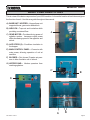
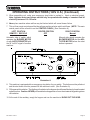
1
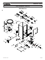
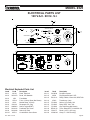
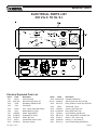
OWNERS MANUAL
MODEL #325
50 YEARS OF QUALITY AND SERVICE
KRENDL MACHINE COMPANY • 1201 SPENCERVILLE AVE
DELPHOS, OHIO 45833 • TELEPHONE 419-692-3060 • FAX 419-695-9301
E - MAIL: [email protected] • WEB SITE: www.krendlmachine.com
CONGRATULATIONS ON YOUR PURCHASE OF KRENDL EQUIPMENT
MODEL #325
OWNER'S MANUAL
FOR ASSURED SAFETY AND CONFIDENCE, PLEASE READ THIS
MANUAL CAREFULLY BEFORE INSTALLING AND OPERATING
YOUR MACHINE.
E-MAIL ADDRESS IS: [email protected]
WEB SITE IS: www.krendlmachine.com
Table of Contents
PAGE
INTRODUCTION. . . . . . . . . . . . . . . . . . . . . . . . . . . . . . . . .
1
GENERAL SAFETY INFORMATION. . . . . . . . . . . . . . . . . . 2-3
DECALS . . . . . . . . . . . . . . . . . . . . . . . . . . . . . . . . . . . . . . 4-5
WARRANTY . . . . . . . . . . . . . . . . . . . . . . . . . . . . . . . . . . . .
6
RETURNED GOODS PROCEDURE and SPECIFICATIONS
7
BASIC COMPONENTS. . . . . . . . . . . . . . . . . . . . . . . . . . . .
8
OPERATING INSTRUCTIONS . . . . . . . . . . . . . . . . . . . . . . 9-12
TROUBLESHOOTING . . . . . . . . . . . . . . . . . . . . . . . . . . . .
13
ELECTRICAL . . . . . . . . . . . . . . . . . . . . . . . . . . . . . . . . . . . 14-16
LADDER DIAGRAM . . . . . . . . . . . . . . . . . . . . . . . . . . . . . . 17-19
PARTS LIST . . . . . . . . . . . . . . . . . . . . . . . . . . . . . . . . . . . . 20-24
GLOSSARY . . . . . . . . . . . . . . . . . . . . . . . . . . . . . . . . . . . .
25
SERVICE RECORD. . . . . . . . . . . . . . . . . . . . . . . . . . . . . .
26
MODEL #325
INTRODUCTION
Thank you for purchasing a KRENDL INSULATION MOVING MACHINE. With over fifty-five years
experience in manufacturing insulation moving equipment, we have designed and built your machine with
the highest quality to provide years of reliable service.
This manual has been prepared to help you obtain the maximum efficiency and service from your Krendl
equipment. The machine is designed to condition and apply insulation with the utmost in dependable
performance. Our primary objective is to build equipment which will provide complete satisfaction so
that you may confidently recommend Krendl to others.
We do not manufacture or sell insulation. Our interest lies only in the proper performance of the equipment we
manufacture. We make no recommendations or guarantees concerning various insulations.
CAUTION:
This manual contains important information regarding the safe assembly and operation of your
machine. We urge you to read it carefully and follow the instructions provided. If your questions are not
answered in this manual, may we hear from you? We want you to be able to operate this unit safely
and confidently.
UNPACKING: Store and unpack carton with correct side up. Unpack your machine IMMEDIATELY and
check for damage in shipping. Place any damage claim with delivering carrier, saving all packing
materials for inspection. Our warranty covers manufacturer's defects only. DO NOT return to shipper.
FILL IN AND RETAIN:
Krendl Machine Company
1201 Spencerville Ave.
Delphos, Ohio 45833 U.S.A.
Telephone:
Fax:
E-mail:
Web Site:
419-692-3060
419-695-9301
[email protected]
www.krendlmachine.com
For your protection in the event of theft or loss, please fill in the information requested for your own
records. This information will be needed for in-warranty repairs. You may also want to attach a copy of
your invoice.
Machine model number_____________
Blower motor manufacturer
_
Serial number
Gear motor manufacturer
_
_
Blower(s) serial number(s)___________
Gear motor serial number________________________
Supplier_________________________
Date of purchase
______________
The model and machine serial numbers are located on the hopper of the machine unit. The blower and
gearmotor serial numbers are located on the motor housing of each unit.
Rev. Date: 1/16/14
Page 1
MODEL #325
GENERAL SAFETY INFORMATION
Important: Read all instructions before operating this unit. This equipment can be potentially
dangerous and must be used in strict accordance with instructions.
Disclaimer Notice: The manufacturer will not be legally responsible for any injury or damage resulting
from the improper use of this equipment or the failure to follow instructions.
Unpacking
Handle cartons with care to avoid damage from dropping or bumping. Store and unpack cartons with the
correct side up. Completely remove machine from the packaging and from any shipping pallet or skid to
which it might be attached. In addition, completely remove all shipping materials from inside the machine
including wheel package, manual, ect....
General Safety
1. Read this manual carefully and become familiar with your machine unit. Know its applications,
limitations, and any hazards involved.
2. This machine was designed and manufactured for specific applications. Do not attempt to
modify the unit or use it for any application it was not designed for. If you have any questions
about your intended use or the machines suitability, ask your dealer/distributor or consult the
factory. The manufacturers' could not possibly anticipate every circumstance that might involve
a hazard. For that reason, warnings in the manual and warning tags or decals affixed to the unit,
are not all-inclusive. If you intend to handle, operate, or service the unit by a procedure or method
not specifically recommended by the manufacturer, first make sure that such a procedure or
method will not render this equipment unsafe or pose a threat to you and others.
Electrical Safety
• The National Electric Code (NEC) in the United States and many international electrical codes require
frame and external electrically conductive parts of this machine to be properly connected to an approved
earth ground. Local electrical codes may also require proper grounding of machine. Consult with local
electricians for grounding requirements in your area.
• Never handle any kind of electrical cord or device while standing in water, while barefoot or while hands
or feet are wet. Dangerous electrical shock will result.
• Use a ground fault circuit interrupter (GFCI) in any damp or highly conductive area. (metal decking or steel work)
• Reference NFPA 79, 70E, or OSHA safe work practices when performing energized work procedures.
Rev. Date: 1/16/14
Page 2
MODEL #325
Safety/Caution
• Be Safe - Keep away from moving parts.
• Be Safe - Make sure all guards and hopper bar are in proper place before operating machine. Guards
and safety devices/switches should not be removed, modified or by-passed. Hands should
never pass below hopper bar.
• Be Safe - Do not remove motors or lift hopper when unit is connected to power supply.
• Be Safe - Make sure machine is properly grounded. Protect all electrical supply cords from sharp
objects, moisture, and other potentially hazardous materials. Keep power cords in good
repair. Electrical service must be performed by a qualified electrician.
• Be Safe - Disconnect power supply before inspecting or adjusting unit.
• Be Safe - Consult a qualified technician to answer questions before attempting to operate, or injury may
result.
• Be Safe - Do not operate machine alone.
• Be Safe - Do not leave machine unattended and energized.
• Be Safe - Turn machine off and disconnect electricity before clearing and feeding jam or attempting to
remove any object dropped in the hopper.
• Be Safe - Keep hands, loose clothing, jewelry and hair away from agitators, gears, chains and other
moving parts.
• Be Safe - Use proper lifting when moving insulation and loading machine.
• Be Safe - Keep work area clear of debris.
• Be Safe - Wear proper safety equipment, including protective gear, such as respirators, eye and ear
protection.
• Be Safe - Violation of the Owner's Manual or safety precautions may void warranty.
Make Sure!
• Hopper is empty of foreign objects before starting.
• Adequate electrical power is supplied or damage to unit will result.
• Blower filter is kept clean and in place when blower is on.
• Machine is turned off immediately if hose is plugged, or blower will overheat.
• Machine must be on before adding insulation.
• Blower(s) must be on, when agitators are running, or machine will bind.
• Agitator motor is not run with hopper empty for more than a few minutes, or damage to seals will result.
• Sprockets, chains, belts and pulleys are correctly aligned and tensioned.
• Pieces of bag are not left in the machine as this can bind and stall your machine.
• This machine should only be used with good quality insulations that are dry, undamaged and that meet
a certain industry specification or quality standards.
Rev. Date: 1/16/14
Page 3
MODEL #325
DECALS
Keeping the filter clean will result in longer
blower life and better performances.
Rotating parts can be dangerous! You can snag clothes,
hair, hands, etc. This can cause serious injury or death.
Indicates which employee inspected the
equipment and on what date.
Manufacturer information is provided here
along with machine model, and serial number.
Rotating parts will be moving in this direction.
Indicates that the electrical box on the machine is in compliance with UL codes.
KMC-01234
Part number for identification and tracking.
Made in the U.S.A.
Identifies what type of insulation should be used with this
machine and that the manual should be read before operating. Warns to be careful around electrical components!
This can cause serious injury or death.
A list of warnings intended to reduce the risk
of serious injury or death.
General safety information intended to reduce
the risk of serious injury or death
Rev. Date: 1/16/14
Page 4
MODEL #325
U.S. (Basic)
U.S.
Overseas
Indicates the controls that start, stop, and run the machine.
Rev. Date: 1/16/14
Page 5
MODEL #325
WARRANTY:
Krendl Machine Company (Company) warrants to each original purchaser (Buyer) of its
machines that such products will be free of manufacturing defects for a period of 2 years from
the date of shipment to the Buyer. (This does not include accessories, pumps, blowers, wall
scrubbers, etc.)
No warranty is made with respect to:
1. Components or accessories manufactured and warranted by others. Warranties for
purchased component parts as supplied from vendor such as engine, electric motor,
blower, gearbox, transmission, etc., if furnished by the manufacturer of the component, are
on file at the Company’s main office and copies will be furnished at request of Buyer.
Component(s), shipping costs prepaid, shall be sent to Company who in turn shall forward
to vendor for evaluation and warranty determination.
2. Any defect caused by repair, alteration and/or adjustment performed by Buyer or customer/
vendor of Buyer without the express written authorization of the Company.
3. The labor costs of replacing parts by parties other than the Company.
4. Any machine that has not been operated and/or maintained in accordance with normal
industry practice and the written recommendations of the Company. (e.g. machine operated with an improperly sized, worn or damaged hose, improper or inattention to preventative maintenance, etc.)
5. The product has been subjected to misuse, negligence or accident or results of any
application or use of the blowing equipment not in accordance with the Company recommendations.
This limited warranty does not cover the free replacement of component parts that become
inoperative due to wear and usage and need to be replaced on a regular basis, including but not
limited to: airlock seal(s), agitator(s), shredder(s), auger(s), fuse(s), switch(es), clutch(es), hose(s),
shaft seal(s), chain(s), belt(s), sprocket(s), pulley(s), bearing(s), cable(s), battery(ies), filter(s),
fan(s), etc.
The Company’s obligation under this warranty is limited to repairing or replacing (at Company
option) any part that is determined by the Company to be suffering from a manufacturing defect.
The Company (at Company option) will provide any required parts and labor to the Buyer. If the
equipment or parts must be returned to the Company for repair, all transportation costs shall be
the Buyer’s responsibility.
THIS LIMITED WARRANTY IS EXPRESSLY IN LIEU OF ANY OTHER GUARANTEES AND / OR
WARRANTIES, ORAL OR WRITTEN, EXPRESSED OR IMPLIED, INCLUDING WITHOUT LIMITATION, THE IMPLIED WARRANTY OF MERCHANTABILITY. NO WARRANTY, EXPRESS OR
IMPLIED, OTHER THAN THE AFORESAID WARRANTY IS MADE OR AUTHORIZED BY COMPANY. COMPANY SHALL NOT BE LIABLE FOR ANY DIRECT, INDIRECT, INCIDENTAL OR
CONSEQUENTIAL DAMAGES TO PROPERTY OR INJURY TO ANY PERSON OR COSTS ASSOCIATED WITH LOSS OF PRODUCTION RESULTING IN LOSS OF REVENUE, PROFITS OR LOSS
OF EQUIPMENT THROUGH THE USE OF THIS EQUIPMENT.
Note: Special job circumstances incurring costs for specialized repair and next day delivery
of parts will not be reimbursed by the manufacturer unless authorized by factory.
Rev. Date: 1/16/14
Page 6
MODEL #325
RETURNED GOODS PROCEDURE:
IF MACHINE WAS NOT PURCHASED DIRECTLY FROM KRENDL MACHINE COMPANY, CONTACT
YOUR SUPPLIER / DISTRIBUTOR.
When returning products to Krendl for repair, first obtain a return goods authorization, at which time you
will be given shipping instructions. The product must be shipped PREPAID:
Krendl Machine Company
1201 Spencerville Ave.
Delphos, Ohio 45833 U.S.A.
Telephone:
Fax:
E-mail:
Web Site:
419-692-3060
419-695-9301
[email protected]
www.krendlmachine.com
Once the unit is received, it will be inspected. In-warranty units will be repaired and returned
immediately. An estimate of repair charges will be provided for out-of-warranty units.
SPECIFICATIONS
MODEL#:
MACHINE:
325
8" Diameter x 8” Length airlock
(20.3 cm Diameter x 20.3 cm Length airlock)
In line helical gear motor (driving the machine)
HEIGHT:
WIDTH (DEPTH):
LENGTH:
WEIGHT:
ELECTRICAL:
49 1/2" (126 cm)
29 1/2" (75 cm)
28 1/2" (72 cm)
145 pounds (66 kg)
120VAC, 15 amp, single input
230VAC, 16 amp, single input
104 CFM
2.0 PSI maximum
2.5” diameter (6.3 cm diameter)
BLOWER VOLUME:
BLOWER PRESSURE:
HOSE OUTPUT:
MAXIMUM FEED RATES:
CELLULOSE: 900 lbs./hr.
WARNING: Recommended hose size, type and length must be used to achieve maximum results. Krendl
cannot guarantee performance of the machine if hoses are undersized, worn, damaged, or
hoses other than those we recommend are used.
BEFORE YOU RUN THIS MACHINE...PLEASE READ THE REST OF THIS MANUAL!!
Rev. Date: 1/16/14
Page 7
MODEL #325
BASIC COMPONENTS: #325
This is a view of the basic components of your #325 machine. It shows the location of each item and gives
the function of each. Use this as a guide throughout the manual.
A) BASE UNIT / HOPPER—Hopper/base unit
supports blower, gear motor and airlock.
B) AIRLOCK—Traps air and insulation while
providing a metered flow.
A
C) GEAR MOTOR—Provides driving power of
agitation system. Increases output power
while decreasing speed of the agitators and
airlock.
D) AGITATORS (2)—Conditions insulation in
the hopper.
E) MAIN CONTROL PANEL—Connects with
main power, allowing operation of unit at
machine.
F) BLOWER—(Not shown) Creates air pressure to blow insulation out of airlock.
G) HOPPER BAR— Hinders operators from
reaching agitators.
C
B
E
G
Rev. Date: 1/16/14
D
Page 8
MODEL #325
OPERATING INSTRUCTIONS (120V U.S.)
1. Read all safety and operating instructions before operating this unit.
2. This unit comes ready for connection with hose, clamps, and power cord. (Not supplied)
3. This unit provides a direct hook-up to 2 1/2" I.D. hose. Slide hose on blower outlet and secure with a
hose clamp to provide safe working conditions. All hose connections should have hose clamps to
prevent air leakage and separation of hose.
4. This unit is supplied with power through a 120V Flush Mount Input Plug located on the Control Panel.
Note: When using extension cord, wire gauge size should not be less than 12-3 and not
exceed 50' in length. (See Voltage Drop Chart Below.)
Ex: A two-wire 20-ampere circuit using 12 AWG with a one-way distance of 25 feet will drop 1.98 volts;
120 volts - 1.98 volts = 118.02 volts as the load voltage.
240 volts - 1.98 volts = 238.02 volts as the load voltage.
Rev. Date: 1/16/14
Page 9
MODEL #325
OPERATING INSTRUCTIONS (120V U.S.) (Continued)
5. When assembling unit, make sure emergency stop button is pushed in. Hook up electrical supply.
Note: Agitator motor and blower should only be operated with steady or constant flow of
electricity between 110-120 volts.
6. Never place machine where airflow may be blocked which will cause blower failure.
7. This unit has a main control panel that has a three position selector switch as follows. (NOTE: This main
control panel will be referred to as the CONTROL PANEL.) (See Illustration A)
LEFT POSITION
REMOTE / RECYCLE
CENTER POSITION
OFF
Automatic side of switch which
operates the BLOWER MOTOR
on with AGITATOR MOTOR with
the 24 Volt AC signal of another
machine.
RIGHT POSITION
Manual
Manual side which operates the
BLOWER MOTOR and the AGITATOR MOTOR when the start
button is pressed.
Illustration A
8. This machine is equipped with an emergency stop button for your safety. This button must be pulled out
and the start button must be pressed for the machine to start. (See Illustration A)
9. Fill hopper with insulation. The first bag of insulation in the hopper should be well broken by hand to assist
agitator action. Caution: NEVER put hands below hopper bar or force-feed material by pushing down
on insulation.
10. At the end of the workday, empty the hopper and use the machine to BLOW OUT THE HOSE.
Rev. Date: 1/16/14
Page 10
MODEL #325
OPERATING INSTRUCTIONS (230V Overseas)
1. Read all safety and operating instructions before operating this unit.
2. This unit comes ready for connection with hose, clamps, and power cord. (Not supplied)
3. This unit provides a direct hook-up to 2 1/2" I.D. hose. Slide hose on blower outlet and secure with a
hose clamp to provide safe working conditions. All hose connections should have hose clamps to
prevent air leakage and separation of hose.
4. This unit is supplied with power through a 230V drop cord located on the side of the machine. Note:
When using extension cord, wire gauge size should not be less than 12-3 and not exceed 50'
in length. (See Voltage Drop Chart Below.)
Ex: A two-wire 20-ampere circuit using 12 AWG with a one-way distance of 25 feet will drop 1.98 volts;
230 volts - 1.98 volts = 228.02 volts as the load voltage.
Rev. Date: 1/16/14
Page 11
MODEL #325
OPERATING INSTRUCTIONS (230V Overseas) (Continued)
5. When assembling unit, make sure emergency stop button is pushed in. Hook up electrical supply.
Note: Agitator motor and blower should only be operated with steady or constant flow of
electricity between 220-230 volts.
6. Never place machine where airflow may be blocked which will cause blower failure.
7. This unit has a main control panel that has a three position selector switch as follows. (NOTE: This main
control panel will be referred to as the CONTROL PANEL and the toggle switch at the end of the remote
cord as the Remote Control Switch.) (See Illustration B)
LEFT POSITION
REMOTE
CENTER POSITION
OFF
Operates the BLOWER MOTOR
and AGITATOR MOTOR with the
remote control switch after the
start button is pressed.
RIGHT POSITION
Manual
Manual side which operates the
BLOWER MOTOR and the AGITATOR MOTOR when the start
button is pressed.
Illustration B
8. This machine is equipped with an emergency stop button for your safety. This button must be pulled out
and the start button must be pressed for the machine to start. (See Illustration B)
9. Fill hopper with insulation. The first bag of insulation in the hopper should be well broken by hand to assist
agitator action. Caution: NEVER put hands below hopper bar or force-feed material by pushing down
on insulation.
10. At the end of the workday, empty the hopper and use the machine to BLOW OUT THE HOSE.
Rev. Date: 1/16/14
Page 12
MODEL #325
TROUBLESHOOTING
IMPORTANT: DO NOT attempt to service unit. (Contact your dealer for further information.)
1. If machine does not run:
a. Make sure emergency stop button is pulled out and start button is pressed.
b. Check MOTOR RESET button. Press to reset. (See Illustration A or B)
c. Check power cords for proper connection.
d. Check 1/2 amp fuse. (See Illustration A or B)
2. Loud knocking sound: (Unplug power supply)
a. Check machine agitators and airlock for foreign objects.
b. Check for misaligned sprockets or loose chain.
3. Poor output from machine or uneven flow through hose: (Unplug power supply)
a. Check for material bridging in hopper.
b. Voltage may be low, try another electrical source. Use proper wire size for
extension cord (#12-3).
c. Check for worn or damaged rubber airlock seals.
4. Blower motor running hot: (Unplug power supply)
a. Clean filter. Blow out surrounding area with air hose.
b. Check for restriction in blowing hose.
5. Agitator motor running hot: (Unplug power supply)
a. Check for insulation build up around motor and blow out with air hose.
b. Low voltage can cause this condition. Try another electrical source (#12-3).
c. Debris jamming airlock. Rotate airlock manually and clean out.
d. Check for sprocket misalignment and bearing wear.
Rev. Date: 1/16/14
Page 13
MODEL #325
120 V.A.C. — 60 Hz
BASIC
ELECTRICAL DIAGRAM:
Periodically, disconnect machine from power source and check all electrical connections and components for broken or loose
wires.
MODEL #325
ELECTRICAL
Rev. Date: 1/16/14
Page 14
MODEL #325
120 V.A.C. — 60 Hz
ELECTRICAL DIAGRAM:
Periodically, disconnect machine from power source and check all electrical connections and components for broken or loose wires.
MODEL #325
Rev. Date: 1/16/14
Page 15
MODEL #325
230 V.A.C. — 50 Hz
ELECTRICAL DIAGRAM:
Periodically, disconnect machine from power source and check all electrical connections and components for broken or loose wires.
MODEL #325
Rev. Date: 1/16/14
Page 16
MODEL #325
LADDER DIAGRAM
MODEL #325
120 V.A.C. — 60 Hz
SINGLE INPUT
(BASIC)
Rev. Date: 1/16/14
Page 17
MODEL #325
MODEL #325
120 V.A.C. — 60 Hz
SINGLE INPUT
Rev. Date: 1/16/14
Page 18
MODEL #325
MODEL #325
230 V.A.C. — 50 Hz
SINGLE INPUT
Rev. Date: 1/16/14
Page 19
MODEL #325
EXPLODED PARTS
#325 Machine
Rev. Date: 1/16/14
Page 20
MODEL #325
#325 PARTS LIST
Item #
Part #
1
325-1-R3
2
325-7-R1
3
325-6-R2
4
325-2
5-1
1507
5-2
107-1
6
1506
7
4511
8
448Z
9
325-3
10
426-3
11
325-5
12
426-7
13
426-6
14
4511-A
15
325-13
16
432
16-1
FSB120
16-2
40052
17
422-ASSY
17
422-ASSY-CE
18
325-10
19
408-A
19
408-C
20
409-C
21
337
22
42518-5
23
42562
24
325-SE
24-1
325-E-US
25
325-E-OS
26
325-8
27
FSB078
28
W-9
29
FW019
30
250600-4
31
543-M-17
32
14-3 SJ
33
ELU06-9
34
RC395A-B
35
RC395-DPDT
35-1
RC395-1
35-2
RC395-2
35-3
1536-7
35-4
109066-9
35-5
RC395-3
35-6
RC395-4
36
18-3 SJ
37
126-B
38
CV101
-199
Rev. Date: 1/16/14
Description
Base and Hopper
Guard, Chain
Guard, Bottom
Agitator (2)
Housing, Flange, 3/4”, 2-Bolt (8)
Bearing, 3/4”, Insert Only (4)
Seal, Felt, 3/4” (4)
#40 Sprocket, 15T x 3/4” (2)
Key, 3/16” x 3/16” x 1” (3)
Airlock w/Rotor
Seal, Airlock, 2-Ply (5)
Cover Plate, Airlock (5)
Seal, Felt, 3/4” (2)
Bearing, 2-Bolt Flange, 3/4” Bore (2)
#40 Sprocket, 12T x 3/4"
#40 Chain, 46” Long
#40 Sprocket, Idler, 17T x 5/8"
Shoulder Bolt, 5/8" x 3/4"
Nut, 1/2-13 x 1" Square
Gearmotor, 1/6HP, 120V (US)
Gearmotor, 1/6HP, 230V (Overseas)
#40 Sprocket, 15T x 5/8”
Blower Motor, 8A, 120V, 60Hz.
Blower Motor, 4A, 230V, 50Hz.
Spacer, Blower 2” (3)
Clamp, Hose, 2” (3)
Hose, 2” Dia., 15” Long
Filter, 6 1/4” x 6 1/4”
Panel, Electrical, Complete, 120V 60Hz
Panel, Electrical, Complete, 120V 60Hz
Panel, Electrical, Complete, 230V 50Hz
Axle
Pin, Cotter, 1/8” x 1” (2)
Wheel, 9” Pneumatic (2)
W 3/4” Flat Washer SAE (4)
Aluminum Handle
Connector, Cord, Liquid Tite, 1/2" Blue (Overseas)
Wire, 14-3 SJ (Overseas)
Plug, European (Overseas)
RC Cord Assy, 100', Style B (Overseas)
RC Service Kit (DPDT)
Switch Housing
Switch Housing Cover with belt clip
Belt Clip
Switch, Toggle, DPDT
Strain Relief
8-16 Plastite Screws (4) (Not Shown)
Wire, 18-3 SJ (100')
Plug, NEMA# 6-15P
Check Valve, 2"
Link Master, #40 NP
Page 21
MODEL #325
ELECTRICAL PARTS LIST
120 V.A.C. 60 Hz. S.I.
(BASIC)
MOTOR
RESET
START
EMERGENCY STOP
POWER INPUT
120 VAC
15 AMP
Electrical Exploded Parts List
Item#
24-1
24-2
24-3
24-4
24-5
24-6
24-7
24-8
24-9
Part#
325-27
KMC-221
433-A
543-M-59
543-M-60
508-2
8075-1
42528
ELU10-10
Rev. Date: 1/16/14
Description
Panel, Electrical
Decal, 325 U.S. On/Off
Manual Reset, 2.5 Amp
Pushbutton On, Green
Plate, Legend - Start (Not Shown)
Switch, Kill, Red
Contact Block
Plug Recessed input 5-15P
Contactor, Relay, 120V Control
Page 22
MODEL #325
ELECTRICAL PARTS LIST
120 V.A.C. 60 Hz. S.I.
FUSE
SELECTOR SWITCH
RECYCLE OFF
MOTOR RESET
START
POWER INPUT
MANUAL
ALARM
EMERGENCY STOP
120 VAC
15 AMP
REMOTE / RECYCLE INPUT
Electrical Exploded Parts List
Item#
24-1-1
24-1-2
24-1-3
24-1-4
24-1-5
24-1-6
24-1-7
24-1-8
24-1-9
24-1-10
Part#
325-22
325-22-D
1532
1533-A
433-A
543-M-2
109066-9
543-M-14
543-M-46
8075-2
Rev. Date: 1/16/14
Description
Panel, Electrical
Decal, 325 Stateside
Fuse Holder
Fuse, 1/2 Amp, Glass (Not Shown)
Manual Reset, 2.5 Amp
Receptacle, RC, Plug
Switch, Toggle (DPDT)
Pushbutton On, Green
Switch, Kill, Red
Contact Block 22mm Green
Item#
24-1-11
24-1-12
24-1-13
24-1-14
24-1-15
24-1-16
24-1-17
24-1-18
24-1-19
24-1-20
Part#
543-M-38
42528
ELU10-11
1530-C
ELU09-4
ELU09-5
ELU09-6
RELAY-10
ELU07-F
151080-49
Description
Pre-Alarm System
Plug Recessed input 5-15P
Relay, E-Mech, Control 24V, DPST-NO
Transformer, 1 Amp
Socket, 8 Pin Relay 16A
Relay, DPDT 120V, 15A
Clip, Hold Down (Not Shown)
Timer / Relay DPDT 12-240VAC 15A
Dinrail, 1 3/8", 2 3/4" Long
Clamp, F/ 1 3/8" Dinrail (2)
Page 23
MODEL #325
ELECTRICAL PARTS LIST
230 V.A.C. 50 Hz. S.I.
SELECTOR SWITCH
REMOTE CONTROL OUTLET
RECYCLE OFF
MANUAL
START
ALARM
EMERGENCY STOP
FUSE
MOTOR RESET
Electrical Exploded Parts List
Item#
25-1
25-2
25-3
25-4
25-5
25-6
25-7
25-8
25-9
25-10
25-11
Part#
325-23
KMC-222
132-B
1532
1533-B
433-A
109066-9
543-M-86
543-M-87
8075-2
543-M-38
Rev. Date: 1/16/14
Description
Panel, Electrical
Decal, Electrical Panel, CE
Receptacle, NEMA# 6-15R
Fuse Holder
Fuse, 1 Amp, Glass (Not Shown)
Manual Reset, 2.5 Amp
Switch, Toggle (DPDT)
Pushbutton On, Green
Switch, Kill, Red
Contact Block 22mm Green
Pre-Alarm System
Item#
25-12
25-12-1
25-13
25-14
25-15
25-16
25-17
25-18
25-19
25-20
25-21
Part#
54-M-33-OS
543-M-85
ELU10-11
1530-C
ELU09-4
ELU09-325
ELU09-6
RELAY-10
ELU07-F
151080-49
ELU10-13
Description
Operator Handle Assy
Switch Disconnect Assy 4P Red
Relay, E-Mech, Control 24V, DPST-NO
Transformer, 1 Amp
Socket, 8 Pin Relay 16A
Relay, DPDT 230V, 10A
Clip, Hold Down (Not Shown)
Timer / Relay DPDT 12-240VAC 15A
Dinrail, 1 3/8", 2 3/4" Long
Clamp, F/ 1 3/8" Dinrail (2)
Cover, E-Mech Relay (Not Shown)
Page 24
MODEL #325
GLOSSARY
BRIDGING
Tendency of insulation to cling in the hopper forming an air pocket above the
airlock. This hinders the normal feeding process of the machine.
CFM
(Cubic feet per minute). A measurement of volume or quantity of air
flowing at a certain rate, or air moving capability, of a blower. It is the
volume of air moved per minute. Higher volume provides increased
coverage and velocity of insulation as it leaves the hose.
COVERAGE
Refers to the amount of insulation coverage, usually measured in square
feet, according to the R-value desired. This information is given on the
insulation package.
PSI
(Pounds of pressure per square inch). The force exerted on a surface by
air/liquid. High-pressure blowers push the insulation through the hose.
Higher pressure provides less hose plugging and increased compaction in
side wall.
PRODUCTION RATE
Pounds of insulation blown per hour.
RPM
(Revolutions per minute). Speed at which the shaft of a rotating device (i.e.
blower fan, agitator) is moving.
R-VALUE
Resistance value. A precise measurement of the insulation's resistance to
heat transfer. The higher the resistance value, the slower the heat will
transfer through the insulating material.
SETTLED DENSITY
The point at which the insulation will not continue to settle further. Any
insulation blown will have a certain amount of progressive settling that
occurs after a period of time. Following the insulation manufacturers
recommendations for bag rate coverage will provide useful information to
accommodate for settling.
SETTLING
Compression or compaction of insulation fibers caused by the weight of the
material, vibration of structure, temperature, and humidity cycles.
Rev. Date: 1/16/14
Page 25
MODEL #325
SERVICE RECORD
DATE
Rev. Date: 1/16/14
MAINTENANCE PERFORMED
COMPONENTS REQUIRED
Page 26
50 YEARS
OF QUALITY AND SERVICE
Made in the U.S.A.
KRENDL MACHINE COMPANY • 1201 SPENCERVILLE AVE
DELPHOS, OHIO 45833 • TELEPHONE 419-692-3060 • FAX 419-695-9301
E - MAIL: [email protected] • WEB SITE: www.krendlmachine.com