1
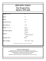
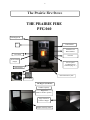
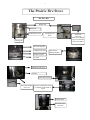
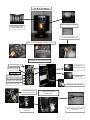
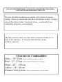
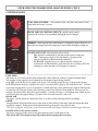
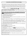
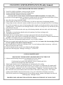
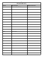
P RAIRIE F IRE
G RAIN E NERGY
I NC .
Owners Manual
THE PRAIRIE FIRE
Model #PFG060
2
SAFETY INSTRUCTIONS
PLEASE READ THE ENTIRE MANUAL BEFORE INSTALLING YOUR
PRAIRIE FIRE GRAIN BURNING STOVE. FAILURE TO FOLLOW
THESE INSTRUCTIONS COULD RESULT IN PROPERTY DAMAGE,
BODILY INJURY OR EVEN DEATH.
♦
♦
♦
♦
♦
♦
♦
♦
♦
♦
♦
♦
♦
♦
♦
♦
♦
♦
ONLY USE RECOMMENDED FUEL.
This unit has passed all safety requirements, however, IMPROPER INSTALLATION
MAY CAUSE FIRE. Please follow installation instructions.
CONSULT LOCAL AND STATE/PROVINCIAL CODES REGARDING
INSTALLATION. THESE CODES MAY VARY FROM THIS MANUAL AND
PERMITS MAY BE REQUIRED.
CONTACT LOCAL BUILDING OR FIRE OFFICIALS ABOUT RESTRICTIONS
AND INSTALLATION INSPECTION REQUIREMENTS IN YOUR AREA.
This unit must be cleaned regularly by following the cleaning and maintenance instructions
provided in this manual.
DO NOT START A FIRE WITHOUT THE BURNING BOX IN PLACE.
DO NOT USE CHEMICALS OR FUELS TO START THE FIRE.
KEEP EXPLOSIVE MATERIALS AWAY FROM THE STOVE AT ALL TIMES.
Cleaning and inspection of vents should be conducted regularly. (Refer to manufacturers
recommendations)
Install smoke detectors near the unit and store a fire extinguisher rated for Class ‘A’ fires
nearby.
DO NOT CONNECT STOVE FLUE TO A CHIMNEY FLUE SERVING ANOTHER
APPLIANCE.
DO NOT CONNECT TO DUCTWORK.
In the event of power outages a back up power supply will be required to operate this unit.
THIS UNIT WILL NOT FUNCTION WITHOUT A POWER SUPPLY.
This unit is equipped with a safety feature that will not allow the auger to operate if the
hopper lid is open.
NEVER ALLOW SMALL CHILDREN TO PLAY NEAR THIS UNIT.
KEEP AREA AROUND CLEAR OF COMBUSTIBLE MATERIALS AND FREE OF
CLUTTER.
ONLY RESPOSIBLE ADULTS SHOULD OPERATE THIS UNIT.
PRE-BURNING OF YOUR STOVE IS RECOMMENDED IN A WELL
VENTILATED AREA ( outdoors) PRIOR TO INSTALLATION.
‘Curing’ of the heat exchanger and paint will occur during first start up resulting in some
initial smoke and odor for a short period.
SAVE THESE INSTRUCTIONS
3
Dear Customer:
Thank you for purchasing the Prairie Fire PFG060
Grain Burning Stove.
We strive to ensure that our product demonstrates quality and safety
while being an affordable alternate heating source for your home.
Your satisfaction is very important to us. Please use this guide for
installing, operating and maintaining your Prairie Fire Stove.
SAVE THIS MANUAL for future reference and follow all safety
instructions.
Sincerely,
Prairie Fire Grain Energy Inc.
4
Table of Contents
Safety instructions
Page 2
Specifications
Page 5
The Prairie Fire Stove
Page 6
Page 7
Page 8
Installation Instructions—Clearances
Page 9
Installation Instructions– Venting Restrictions
Page 10
Venting Installation
Page 11
Operating Instructions
Page 12
Start Up and Shut Down
Page 13
Cleaning and Maintenance-Daily
Page 14
Cleaning and Maintenance-Weekly/Annual
Page 15
Trouble Shooting
Page 16
Page 17
Warranty
Page 18
Owners Registration Card - Return copy
Page 19
- Customer copy
Page 20
Contact Information
Page 21
PFG 060 Parts List
Page 22
Page 23
Venting Instructions
Appendix A
5
SPECIFICATION
The Prairie Fire
Model # PFG 060
Height (With pedestal)
39”
Width
33”
Depth
27.0”
Exhaust Flue Size
3.0”
Intake Flue size
6.5/8”
Weight (With Pedestal)
320 lb.
145.2 kg.
Maximum Capacity
8 lbs/hr.
3.6 kg/hr
Options
Trim:
⇒ Polished stainless
⇒ Brass
Available Colors
Black
Electric Rating
120V / 60hz / 3 amps
Specifications are subject to change without notice.
FUEL RECOMMENDATIONS
This unit has been tested and certified for WHEAT as a source of fuel.
CAUTION: ENSURE THAT SUPPLY OF GRAIN BEING USED IS FREE OF
FOREIGN OBJECTSAND EXCESS STRAW AND CHAFF
WHICH MAY CAUSE HARM TO THIS UNIT.
DO NOT attempt to burn garbage or other inappropriate materials in this unit.
6
The Prairie Fire Stove
THE PRAIRIE FIRE
PFG 060
Grain hopper lid
Grill
Control Panel
Window Trim
Brass/stainless
Door latch
Fire Box
Service Panel
(Auger)
Service panel
(Combustion fan,
Cleanout plug, etc.)
Pedestal base
Ash collection tray tabs
Pedestal Bolts
The Hopper (Grain Fill)
1 Bushel Capacity
Hopper lid
Must be closed to operate
Auger located at
bottom of hopper
Hopper lid safety switch
7
The Prairie Fire Stove
The Fire Box
Hinged Top
Splitter bar
Combustion air inlet
Combustion Air
Holes
Poker Tool
(060-135)
Used to raise hinged
top of fire box and
remove the clinker
Locking tabs
Fuel feed drop tube
Combustion air feed
Back wall of
burning chamber
Fire Box bracket
Air wash
Stainless or brass trim
Window
Ash Collection Tray
Removable handle
(060-110)
Storage compartment at back
of pedestal where handle is
stored
Exhaust outlet
Distribution Fan
(060-125)
8
The Heat Exchanger
Inside of burning chamber
Heat Exchanger tubes
located behind grill
Cleaning Brush(060-117)
Refer to “Heat Exchanger Cleaning” Page 19
Inside Access Panel Control Side
Cycling Timer(060-131)
Combustion fan
air proving switch
Manual reset button
Thermostats
200 man (060-122)
Cleanout plug
90 (060-118) Auger run
110 dist. fan (060-120)
110 auto off (060-119)
Combustion Fan (060-124)
Auger safety switch
200 auto (060-121)
Auger Motor
(060-123)
Inside Access Panel
Hopper Side
Auger Shaft with Flighting
060-140
9
FOLLOW RECOMMENDED CLEARANCES AND RESTRICTIONS WHEN
INSTALLING AND OPERATING THIS UNIT
This unit should be installed on an outside wall to allow for proper
venting. Choose a location that will allow distribution of heat—an open
concept floor plan is ideal. A protective base constructed of non
combustible material is recommended.
The floor protector must cover the surface area that extends 16” in
front of the load door , 8” from the sides and back to the
chimney connector.
Clearance to Combustibles
Sides—10”/25cm (Service panels must be accessible)
Rear—1”/ 2.5 cm ( Plus required allowance for venting )
Front—48” / 120 cm
Above—16”/ 40 cm
Exhaust Vent system- (Refer to manufacturers specifications)
10
INSTALLATION
⇒
⇒
⇒
⇒
⇒
PRE-BURNING OF YOUR STOVE IS RECOMENDED IN A WELL VENTILATED AREA
( Outdoors) PRIOR TO INSTALLATION.
‘Curing’ of the heat exchanger and paint will occur during first start up resulting in some
initial smoke and odor for a short period.
REMOVE ALL PACKING MATERIAL FROM STOVE AND REMOVE CONTENTS PACKAGED
IN HOPPER AND/OR INSIDE BURNING POT
Choose a location on an outside wall with access to a properly grounded 115V AC
receptacle that will allow optimum heat movement throughout your building.
When installing manufacturers venting system take caution in avoiding wiring and pipes.
NEVER CONNECT THE HEATER FLUE TO A CHIMNEY FLUE SERVING
ANOTHER APPLIANCE.
DO NOT INSTALL A FLUE DAMPER IN THE EXHAUST VENTING OF THIS UNIT.
PLEASE FOLLOW RECOMMENDED INSTALLATION
AND OPERATING INSTRUCTIONS
DO NOT locate the vent termination:
⇒
⇒
⇒
⇒
⇒
⇒
Within 6 feet ( 1.8 meters) of a mechanical air supply inlet in the building.
Above a gas meter/regulator within 3 feet ( 900 mm) horizontally of the vertical center line of the
regulator
Within 6 feet (1.8 meters) of gas service regulator vent outlet.
Less than 1.0 feet (300mm) above grade.
Within 3.3 feet (1 meter) of a building opening or air inlet of another appliance.
Within 3.3 feet (1 meter) of property boundary.
INSTALL VENT CLEARANCES SPECIFIED BY THE VENT
MANUFACTURER
INSTALLATION IN MOBILE HOMES
Consult local and state/provincial codes regarding installation in mobile homes which
should be in accordance with the Manufactured Home and Safety Standard (HUD), CFR
3280, part 24
⇒ DO NOT INSTALL IN A SLEEPING ROOM.
⇒ THE STRUCTURAL INTEGRITY OF THE MOBILE HOME, FLOOR, WALL, AND
CEILING/ ROOF MUST BE MAINTAINED.
⇒ PLEASE REFER TO VENTING RECOMMENDATIONS IN APPENDIX *A *
WHICH IS ATTACHED TO THIS MANUAL.
⇒ PEDESTAL MUST BE SECURED TO THE FLOOR OF THE MOBILE HOME . DO
NOT over-tighten bolts in the pedestal. Over– tightening will cause damage to the
pedestal of your stove.
⇒
11
VENTING INSTALLATION
USE ONLY CERTIFIED ZERO CLEARANCE DIRECT VENTING
AVAILABLE FROM YOUR
PRAIRIE FIRE DEALER
Choose location inside building for installation on an outside wall that will allow
optimum heat distribution.
Inspect area where vent will pass through wall and confirm location meets
recommendations and is free from all obstructions.
FOLLOW MANUFACTURERS INSTALLATION
INSTRUCTIONS
INSTALL VENT AT CLEARANCES SPECIFIED BY THE VENT
MANUFACTURER
DO NOT INSTALL A FLUE DAMPER IN THE EXHAUST
VENTING SYSTEM OF THIS UNIT
*For complete venting installation instructions please
refer to APPENDIX “ A”
12
OPERATING THE PRAIRIE FIRE GRAIN BURNING STOVE
CONTROL PANEL
FUEL FEED CONTROL— this control switch will allow the control of fuel
being delivered to the f ire box.
ROOM AIR FAN CONTROL SWITCH- variable speed control
regulates the volume of air circulating through the heat exchanger.
PRIMER– used to prime auger when hopper is completely empty when new or
when the fuel supply has been completely emptied from the hopper during use.
ON/OFF/AUTO OFF- three position rocker switch
ON– Starts the combustion air fan and provides power to the unit.
OFF– Turns power supply off to unit with the exception of the
room air fan which is thermostatically controlled.
AUTO OFF– Supplies power to a thermostat that will provide
an automatic off function that is used when the unit is cooling down for
cleaning or to shut unit down if fuel hopper is emptied.
FUEL FEED
The rotary on -off switch and fuel feed combination control allow the control of grain feeding the flame.
The amount of heat required can be adjusted by the amount of grain being released.
In the OFF position, the power supply to the auger is off which prevents the flow of grain to the fire box.
In the ON position, the power supply to the auger is on which allows grain to flow into the fire box. The fuel
feed switch ranging from 1 to 10 is regulated by a timed metering system ,allowing the control of the amount
of grain that is fed into the firebox, thus allowing to control the amount of heat produced. When set on 1for
example, the grain will be metered for approximately 1 second, allowing a 4 second burn time. When set on 2
it will meter grain for approximately 2 seconds with a 4 second burn time, and so on.
ROOM AIR
The rotary, variable speed fan controls the flow of air that circulates through the heat exchanger.
PRIME
This push button switch provides power to the auger to allow filling of the auger when the hopper has been
completely emptied. Firmly press and hold button until grain begins to drop into fire box.
*This unit is equipped with a safety switch that will not allow the auger to function with the hopper lid open.*
ON/OFF/AUTO OFF ( Power Switch)
This rocker switch provides power to the unit and turns on the combustion air fan .
This switch MUST be turned to the OFF position before opening the front door.
13
OPERATING THE PRAIRIE FIRE GRAIN BURNING STOVE
START UP
1. Plug power cord into grounded 115V AC receptacle.
2. Open hopper lid and fill grain. Use only grain that is recommended for this unit which has been inspected
for foreign objects. This will prevent unnecessary damage to your stove. DO NOT use grain with
excessive amounts of straw and chaff.
3. Close hopper lid. LID MUST BE CLOSED FOR AUGER TO FUNCTION.
4. Open front door using the detachable handle.
5. Place wood pellets in the fire box to just below the top line of air holes.
6. Check the position of the fire box to ensure it is secure against the back wall of the burning chamber.
7. Light wood pellets using an approved catalyst, adhering to manufacturers guidelines. NEVER USE
GASOLINE, GASOLINE-TYPE LANTERN FUEL, KEROSENE, CHARCOAL LIGHTER
FLUID, OR SIMILAR LIQUIDS TO START OR ‘FRESHEN UP’ A FIRE IN THIS UNIT. KEEP
ALL SUCH LIQUIDS WELL AWAY FROM THE HEATER WHILE IT IS IN USE.
8. Quickly close front door and latch tightly. Turn POWER SWITCH to the ON position
9. Prime auger by pressing and holding the PRIMER BUTTON until grain begins to flow into the fire box.
Upon initial start up or when the hopper has been completely emptied, the priming process will take
approximately 2 to 3 minutes. Remove handle from stove and store in back opening of pedestal out of
reach of children.
10. Turn FUEL FEED CONTROL to #1 on the rotary dial.
11. When the heat exchanger reaches operating temperatures ( 5 to 10 minutes), the auger will
thermostatically activate and begin feeding grain into the fire box. Gradually adjust the FUEL FEED
CONTROL to the desired setting. Over feeding will result in grain backing up in feed tube and a build up
of grain in the fire box which will eventually extinguish the flame. Use a higher setting to achieve more
heat and a lower setting to achieve less heat.
12. Turn ROOM AIR FAN CONTROL SWITCH to the low setting on the rotary dial. As the temperature
increases, the room air blower will thermostatically activate. The variable speed fan will require
adjusting according to desired temperature requirements. When operating the unit on a low setting,
adjust the room air fan control switch to a low speed. When operating the unit on mid range on the fuel
feed control, adjust the room air fan control switch to half way between low and high speed. When
operating on high range fuel feed control, adjust the room air fan to high speed. The top of the unit should
remain warm to the touch, not hot. This unit is equipped with sensors that will prevent overheating.
SHUT DOWN
1. Turn FUEL FEED CONTOL SWITCH to the OFF position.
2. Turn POWER SWITCH to the AUTO–OFF position. Turn room air fan to high
(this will cool the heat exchanger more quickly).
** The auto-off feature will shut down the unit when cooled down completely.**
14
CLEANING AND MAINTENANCE (Daily)
When using grain as a fuel source in this unit, the ash that is collected in the fire box after
burning will become solid and fused with a glassy appearance. This is known as a “clinker”.
This “clinker” will continue to build inside the fire box forming to the shape of the fire box. If
not removed in time, the ash will continue to build up and eventually the flame will become
extinguished.
CAUTION—ALWAYS TURN POWER SWITCH TO OFF POSITION BEFORE
OPENING THE DOOR
DAILY –REMOVING THE ASH (CLINKER)
If operating this unit on a continuous basis, “clinker” must be removed approximately every
12 hours. *The time between ash removal will vary with types and quality of grain being used.
This can be done without extinguishing the flame, if done quickly by following the steps
below:
1. Turn FUEL FEED to OFF position.
2. Turn ROOM AIR FAN switch to the OFF position.
3. Turn POWER switch to the OFF position
4. Open door using detachable handle.
5. With pointed end of poker, lift hinged top of fire box to open position. Loosen “clinker”
with poker and tip on its side.
6. Use tongs to grip the clinker turning it over to drop the glowing embers back into the fire
box.
7. Remove the clinker from stove and place it into a metal fire resistant container with lid.
The closed container of ashes should be placed on a noncombustible floor or on the
ground, well away from all combustible materials, pending final disposal. If the ashes are
disposed of by burial in soil or otherwise locally dispersed, they should be retained in the
closed container until all cinders have thoroughly cooled.
8. Return hinged top of fire box to closed position. Ensure fire box is secured tight against
the back wall of the burning chamber.
9. Close door tightly.
10.Remove handle and store out of reach of children.
11. Turn POWER switch to ON position.
12.Turn FUEL FEED CONTROL to #1 and gradually adjust upward to desired setting as
flame increases.
13.Turn ROOM AIR FAN CONTROL to low speed and gradually adjust to desired air flow.
** If operating on a low FUEL FEED setting for extended periods of time, turn FUEL FEED
CONTROL to medium setting (5 on the rotary dial) for a few minutes to build up the ember
bed before removing the clinker. This will reduce the risk of loosing the flame.
**If operating this stove on a high setting for long periods of time it may be necessary to
remove the clinker more often.
**If the clinker sticks to the fire box, a small amount of wood pellets may be added to the
grain when filling the hopper.
15
CLEANING AND MAINTENANCE (Weekly/Annual)
HEAT EXCHANGER CLEANING ( WEEKLY)
1. Turn FUEL FEED CONTROL switch to the OFF position.
2. Turn the POWER SWITCH to the AUTO-OFF position.
3. Turn ROOM AIR CONTROL SWITCH to HIGH.
*ALLOW UNIT TO COOL DOWN COMPLETEY BEFORE PROCEEDING TO NEXT STEP*
(Cool down will take approximately 10 minutes at which time the unit will shut down and all fans will stop.
It is then safe to proceed to clean your unit.)
4. Open front door using detachable handle.
5. Check to make sure fire box is cool to the touch. Lift fire box and remove from burning chamber.
6. Using a shop vacuum or hot ash vacuum (available from your dealer or through Prairie Fire Grain Energy
Inc.), hold vacuum hose at corner of front opening while using the wire brush provided to insert into heat
exchanger tubes. Twist brush to work through each tube to the end, working loose any ash that may have
collected inside the tube.
7. Repeat process to clean each tube at the top of the burning chamber and at the back wall of the burning
chamber.
8. Thoroughly vacuum burning chamber and at the opening of each heat exchanger tube.
9. Clean and vacuum fire box.
10. Return fire box to burning chamber securing it tight against the back wall and locking in place.
11. Clean glass with a glass cleaner recommended for fireplace and related appliances. (Follow manufacturers
guidelines.) Treat glass with care to avoid damage or breakage.
12. Close front door with detachable handle and store out of reach of children.
13. Open service panel on the right side of stove ( control panel side) and remove the clean out plug. Failure
to clean regularly will result in reduced efficiency.
14. Insert vacuum hose to clean loose collection of ash. Use wire brush provided to loosen any visible ash
that may be stuck on and vacuum.
15. Lubricate threads on plug an anti-seize lubricant and replace plug.
16. Start stove following steps 5 through 14 on Page 13. START UP
ANNUAL MAINTENANCE
⇒
DISCONNECT POWER SUPPLY BEFORE SERVICING THIS UNIT.
Lubricate motor bearings using an oil recommended for electric motors.
( Follow manufacturers directions.)
*Combustion fan located on the right side of stove (control panel side)
*Room air fan located at the back of the unit.
⇒ Inspect and clean the vent kit. If perforations are noticed replace the venting.
⇒ Soot and Fly Ash : Formation and Need for Removal– The products of combustion will contain small
particles of fly ash. The fly ash will collect in the exhaust venting system and restrict the flow of flue
gases. Incomplete combustion, such as occurs during startup, shutdown, or incorrect operation of this
unit will lead to some soot formation which will collect in the exhaust venting system. The exhaust
venting system should be inspected at least once every year to determine if cleaning is necessary.
When not in operation for extended periods of time (during summer months), thoroughly clean the unit
following steps 4 through 15 above.
PROPER CARE AND MAINTENANCE WILL PROLONG THE LIFE OF YOUR STOVE
16
TROUBLE SHOOTING
PROBLEM
POSSIBLE CAUSE
Small flame/Flame goes out.
∗
∗
Fuel feed control set at low
setting
Room Air fan control set on
high when grain feed control is
on low
∗
Auger jammed
SOLUTION
∗
*
∗
∗
∗
Grain flow restricted
Lazy Flame
∗
Build up of ash inside heat
exchanger
Room air fan starts and stops
* Fuel feed control set on low and
room air fan control set on high.
Burnt grain smell in your home
∗
Smoked glass
Leaking door seal/gasket
∗
Clean heat exchanger. Refer to Page 15
- Heat Exchanger Cleaning
∗
Adjust room air fan control to low.
Always operate the room air fan on low
when grain feed control is set on low.
Refer to page 13 (#12) Operating Your
Prairie Fire Stove
∗
Examine seals and adjust or replace as
necessary
Examine and clean venting system.
Replace if necessary.
∗
Obstruction in exhaust pipe/
perforations in venting system.
∗
∗
Improper burn
∗
∗
Obstruction of air wash system
∗
Exhaust fumes being drawn into
fresh air intake
∗
Over feeding grain
∗
Clinker not removed before
reaching the top of the fire box
∗
∗
Grain backing up in tube and building up in
fire box
∗
∗
Stove will not turn on when power switch is in ∗
the on position
∗
∗
Stove unplugged
Faulty power switch
Stove has overheated and the
200 degree manual reset thermostat has (060-122) been
activated
Check fuel feed control and adjust as
required
Adjust Room Air fan control to low
when grain feed control is on low range.
Refer to page 13 (#12) Operating your
Prairie Fire Stove
Open left service panel and remove
auger inspecting for obstruction
Empty grain hopper, remove auger and
inspect for obstructions. Clean and
replace auger.
∗
∗
∗
When using grain with increased
moisture levels, smoldering may occur
resulting in smoking of glass.
Remove fly ash along ledge of front door
opening inside the burning chamber. If
this does not correct the problem Refer
to Page 15—Heat Exchanger Cleaning
( Weekly)
Check that exhaust cap is extended away
from fresh air intake. Examine the
venting system for perforations. Replace
if necessary.
Reduce setting on Fuel Feed Control.
Refer to Page 13 (# 10) Start Up
Remove clinker Refer to Page 14
Cleaning and Maintenance—(Daily)
Removing the Clinker
Plug in stove
Replace Switch
Press red reset button on snap disc
(See page 8—manual reset button)
17
TROUBLESHOOTING
PROBLEM
POSSIBLE CAUSE
Room Air fan making excessive noise
∗
∗
∗
SOLUTION
Loose mounting screws
Access panels loose
Grill may have been bent
during shipping.
Defective motor
Fan requires annual
maintenance
∗
∗
∗
∗
Tighten screws
Secure access panels
Examine grill and adjust as necessary.
Replace motor
∗
Clean and oil fan motor Page 15 Annual
Maintenance
∗
Thermostat has not reached
operating temperature
∗
∗
∗
∗
Defective switch
Defective blower
Loose or broken wire
Defective room air control
thermostat
∗Refer to Page 13 (#12) Operating the Prairie
Fire Grain Burning Stove– Start Up
∗
∗ Replace
∗ Replace
∗ Adjust
∗ Replace
Auger motor making excessive noise
∗
Obstruction in auger assembly ∗
Turn Fuel Feed Control to OFF position.
Empty grain hopper, remove auger flighting
and remove obstruction.
Auger will not engage
∗
Hopper lid not closed tightly
∗
∗
Burning chamber has not
reached operating
temperature.
∗
This unit is equipped with a safety feature
that will not allow the auger to operate if the
hopper lid is not secured
Refer to Page 13 (#11) Operating the Prairie
Fire Grain Burning Stove– Start Up
Replace
Replace
Replace
Replace
Replace
Empty grain hopper, remove auger and
inspect for obstructions. Clean and replace
auger.
∗
∗
Room Air Fan won’t engage
∗
∗
∗
∗
∗
∗
Combustion Air Fan making excessive
noise
∗
∗
∗
Combustion fan won’t engage
∗
∗
∗
∗
∗
Defective auger thermostat
Defective Fuel Feed Control
Defective Off time/timer
block control
Defective safety thermostat
Defective auger motor
Auger jammed
∗
∗
∗
∗
∗
∗
Mounting bolts may have
become loose in shipping
Fresh air tube loose
Wiring harness touching
housing
∗
Tighten mounting bolts
∗
∗
Adjust and secure fresh air tube
Adjust harness away from housing.
Power Switch in Auto-Off
position before system is fully
engaged
Fuse burned out (7 amp)
Defective POWER switch
Defective combustion fan
Loose or broken wire
∗
Turn POWER SWITCH to the On position
until system is fully engaged.
Replace fuse
Replace
Replace
Examine and adjust
∗
∗
∗
∗
IF PROBLEM PERSISTS, CONTACT YOUR DEALER FOR ASSISTANCE.
18
LIMITED WARRANTY
This warranty is valid for a period of 1 year from the date of purchase during which time,
Prairie Fire Grain Energy Inc., will repair or replace, at its option, any part defective in
materials or workmanship affecting the operation of this unit. This warranty is limited to parts
only and does not include labour and shipping to and from place of warranty.
Damage caused by abuse, accidents, improper installation, corrosion due to improper care and
maintenance or improper use will not be covered by this warranty. Exclusions to this warranty
are as follows: glass, trim , gasket materials and fire box.
Warranty claims should be made to your dealer.
Your Prairie Fire Dealer
WARRANTY CLAIM
Date:_________________________
Customer Name:_____________________________________
Customer Signature:__________________________________
Reason for warranty claim:____________________________
_________________________________________________
Dealer Name:________________________________________
Dealer Signature:____________________________________
19
OWNERS REGISTRATION CARD
Date of purchase:__________________________________
Name :__________________________________________
Address:_________________________________________
Telephone :_______________________________________
Model #:_________________________________________
Serial #__________________________________________
Dealers Name:____________________________________
PLACE
POSTAGE
HERE
Prairie Fire Grain Energy Inc.
P.O. Box 250
Bruno, Saskatchewan
Canada
S0K 0S0
Return to Prairie Fire Grain Energy Inc.
20
OWNERS REGISTRATION CARD
Date of purchase:__________________________________
Name :__________________________________________
Address:_________________________________________
Telephone :_______________________________________
Model #:_________________________________________
Serial #__________________________________________
Dealers Name:____________________________________
Prairie Fire Grain Energy Inc.
P.O. Box 250
Bruno, Saskatchewan
Canada
S0K 0S0
Keep this copy for your records.
21
The Prairie Fire
Model # PFG060
Is manufactured
by
MIFAB MANUFACTURING INC.
101 Canola Ave
North Battleford, SK
S9A 2Y3
FOR
PRAIRIE FIRE GRAIN ENERGY INC.
BOX 250
BRUNO, SK
S0K 0S0
PH: 1-306-369-2825
FX: 1-306-369-2351
EMAIL: [email protected]
WEBSITE: www.grainburningstoves.ca
YOUR PRAIRIE FIRE DEALER
22
PFG 060 PARTS LIST
PART #
DESCRIPTION
The Prairie Fire PFG 060
PARTS AND ACCESSORIES
060-100
Gold Molding
060-101
Chrome Molding
060-102
Combustion fan gasket
060-103
Rope gasket - braid
060-104
Switch Panel Decal
060-105
Wiring Decal
060-106
Door Glass
060-107
Door glass gasket
106-108
Door glass retainer
060-109
Door glass screws
060-110
Door handle
060-111
Front door
060-112
Front Door decal plate—Brass
060-113
Front Door decal plate—Silver
060-114
Hinge pins
060-115
Touch up paint
060-116
Auger Bushing
060-117
Cleaning Brush
ORDER CHECKLIST
23
PFG 060 PARTS LIST (continued)
060-118
Auger motor thermostat ~ 90 auto
060-119
Auto off switch thermostat ~110 auto
060-120
Distribution Fan thermostat ~ 110 auto
060-121
Hopper high limit thermostat ~200 auto
060-122
High limit thermostat~ 200 Man
060-123
Auger Motor
060-124
Combustion fan~ small fan
060-125
Distribution fan ~ large fan
060-126
7 amp fuse
060-127
Fuse holder
060-128
Fuel Control
060-129
Primer Switch
060-130
Hopper Switch
060-131
Cycling timer
060-132
Rocker switch
060-133
Room air fan speed control
060-134
Combustion fan air proving switch
060-135
Poker Tool
060-136
Owners Manual
060-137
Control knobs
060-138
Fire Starter alcohol gel ~ 16 oz.
060-139
Stainless Steel Fire Box
060-140
Auger shaft with flighting
060-141
Wing panel latch
060-142
Ash collection tray