1
PROJECT MANUAL BID SET Charles B. Aycock High School Addition & Renovation Wayne County Public Schools Pikeville, North Carolina Architect’s Project No. 532801 MORRISVILLE, NORTH CAROLINA STROUD, PENCE & ASSOCIATES STRUCTURAL ENGINEERS RALEIGH, NORTH CAROLINA THE TIMMONS GROUP CIVIL ENGINEERS/ LANDSCAPE ARCHITECTS RALEIGH, NORTH CAROLINA PROGRESSIVE DESIGN COLLABORATIVE PLUMBING/MECHANICAL/ELECTRICAL ENGINEERS RALEIGH, NORTH CAROLINA FOODSERVICE CONSULTANTS STUDIO FOODSERVICE DESIGN MONTPELIER, VIRGINIA A/E’s Project No. 530498 set No. October 24, 2014 • VOLUME 2 OF 2 • LANDSCAPE ARCHITECT Blake Hall, PLA, PE License No. 1489 The Timmons Group 5410 Trinity Road, Suite 112 Raleigh, North Carolina 27607 Telephone Number: 919-859-5666 STRUCTURAL Collette Ramirez, PE License No. 036708 Stroud, Pence & Associates 4904 Professional Court, Suite 200 Raleigh, North Carolina 27609 Telephone Number: 919-782-1833 Fax Number: 919-782-7630 PLUMBING/ MECHANICAL ENGINEER Steve W. Campbell, PE License No. 025020 Progressive Design Collaborative 2900 Rowland Rd, Suite 100 Raleigh, NC 27615 Phone Number: 919-790-9989 ELECTRICAL ENGINEER Robert A. Wolff, PE License No. 32593 Progressive Design Collaborative 2900 Rowland Rd, Suite 100 Raleigh, NC 27615 Phone Number: 919-790-9989 Charles B. Aycock High School Addition & Renovation Wayne County Public Schools Pikeville, North Carolina Architect’s Project No. 532801 TABLE OF CONTENTS VOLUME 1 DIVISION 00 BIDDING AND CONTRACTUAL REQUIREMENTS Invitation to Bid Instructions to Bidders (AIA Document A701, 2007 edition) Prebid Question Form Geotechnical Engineering Study (For Reference Only) Bid Form Bid Bond (AIA Document A310, 2010 edition) Substitution Request Form Standard Form of Agreement Between Owner and Contractor (AIA Document A101, 2007 edition) Performance Bond (AIA Document A312, 2010 edition) Payment Bond (AIA Document A312, 2010 edition) General Conditions of the Contract for Construction (AIA Document A201, 2007 edition) SPECIFICATIONS DIVISION 1 - GENERAL REQUIREMENTS 010200 011000 General Sitework Requirements Summary 012100 Allowances 012110 Sitework Allowances 012200 012300 Unit Prices Alternates 012500 Substitution Procedures 012900 013100 Payment Procedures Project Management and Coordination 013200 Construction Progress Documentation 013300 Submittal Procedures 014000 014110 Quality Requirements Statement and Schedule of Special Inspections 015000 Temporary Facilities and Controls 016000 Product Requirements 017300 017419 Execution Construction Waste Management and Disposal 017700 Closeout Procedures 018119 Indoor Air Quality Requirements 018317 Exterior Enclosure Air Barrier Requirements TABLE OF CONTENTS TOC - 1 Charles B. Aycock High School Addition & Renovation Wayne County Public Schools Pikeville, North Carolina Architect’s Project No. 532801 DIVISION 2- EXISTING CONDITIONS 024113 024119 Selective Site Demolition Selective Structure Demolition DIVISION 3 – CONCRETE 030513 Concrete Water Vapor Reducing Admixture 033000 Cast-In-Place Concrete 034113 034200 Precast Concrete Hollow Core Planks Precast Concrete U-Lintels 034500 Architectural Precast Concrete (APC) - Plant Cast DIVISION 4 - MASONRY 042000 Unit Masonry DIVISION 5 - METALS 051200 Structural Steel Framing 052100 053100 Steel Joist Framing Steel Decking 054000 Cold Formed Metal Framing 055000 Metal Fabrications 055100 Metal Stairs DIVISION 6 - WOOD PLASTICS AND COMPOSITES 061000 Rough Carpentry DIVISION 7 - THERMAL AND MOISTURE PROTECTION 071326 Self-Adhering Sheet Waterproofing 072100 Thermal Insulation 072726.16 Fluid-Applied Vapor-Retarding Membrane Air Barriers 072727 Sprayed Polyurethane Foam Air Barrier 074113 Metal Roof Panels 074243 Composite Wall Panels 075423 Thermoplastic Polyolefin (TPO) Roofing 076201 Flashing, Sheet Metal and Roofing Accessories 078100 Applied Fireproofing 078413 Penetration Firestopping 079200 Joint Sealants TABLE OF CONTENTS TOC - 2 Charles B. Aycock High School Addition & Renovation Wayne County Public Schools Pikeville, North Carolina Architect’s Project No. 532801 079500 Expansion Control DIVISION 8 - OPENINGS 081113 Steel Doors and Frames 081416 Flush Wood Doors 083113 083323 Access Doors and Frames Overhead Coiling Doors 083513 Accordion Folding Fire Door 084113 085113 Aluminum Entrances, Storefront Aluminum Windows 087100 Door Hardware 088000 Glazing DIVISION 9 - FINISHES 092216 Cold Formed Steel Framing - Non-Structural 092900 093000 Gypsum Board Tiling 095113 Acoustical Panel Ceilings 096513 096519 Resilient Base and Accessories Resilient Floor Tile 096623 Resinous Matrix Terrazzo Flooring 096813 Tile Carpeting 096723 098141 Resinous Flooring Acoustical Wall Panels 099100 Painting DIVISION 10 - SPECIALTIES 101100 Visual Display Surfaces 101200 Display Cases 101400 Signage 102113 Solid-Polymer Toilet Compartments 102800 Toilet and Bath Accessories 104400 105113 Fire-Protection Specialties Metal Lockers 105613.16 Metal Storage Shelving 107500 Protective Covers 107316 Building-mounted Canopies TABLE OF CONTENTS TOC - 3 Charles B. Aycock High School Addition & Renovation Wayne County Public Schools Pikeville, North Carolina Architect’s Project No. 532801 107500 Flagpoles DIVISION 11 - EQUIPMENT 114000 Foodservice Equipment DIVISION 12 - FURNISHINGS 122113 Horizontal Louver Blinds 123216 Manufactured Plastic-Laminate-Faced Casework 123553 Wood Laboratory Casework DIVISION 13 - SPECIAL CONSTRUCTION Not Used DIVISION 14 - CONVEYING SYSTEMS 142400 Hydraulic Elevators VOLUME 2 DIVISION 22 - PLUMBING 220100 Plumbing General Provisions 220200 Plumbing Coordination Drawings 220523 220529 Valves (Domestic Supply) Pipe Hangers and Supports 220553 Plumbing Identification 220563 Electrical Work – Plumbing 220579 220719 Unsuitable soil – no additional cost Pipe Insulation – Storm, Domestic Water Supply, Waste 221116 Domestic Water - Copper - Leadfree 221119 Piping Specialties 221123 221316 Pumps - Recirculation Storm, Sanitary Waste – Cast Iron 221319 Grease Interceptor 221420 Pumps - Sump 224200 Commercial Plumbing Fixtures – Lead Free DIVISION 23 - MECHANICAL 230000 Mechanical Alternates 230101 HVAC General Provisions TABLE OF CONTENTS TOC - 4 Charles B. Aycock High School Addition & Renovation Wayne County Public Schools Pikeville, North Carolina Architect’s Project No. 532801 230501 Division of Work 230512 Electrical Work 230513 230529 Motors and Motor Starters Pipe Hangers and Supports 230549 Vibration Isolation 230553 Mechanical Identification 230570 230593 Mechanical Coordination Drawings Testing, Adjusting and Balancing 230714 Insulation (Wrapped Round Duct) 230715 Insulation (Wrapped Ductwork) 230723 230923 Pipe Insulation (Refrigerant) Building Management System 232313 Pipe and Pipe Fittings (Refrigerant) 232316 Piping Specialties (Refrigerant) 233113 233313.16 Spiral Ductwork Fire Dampers 233346 Flexible Ductwork (Medium/High Pressure) 233347 Flexible Ductwork (Low Pressure) 233416 233420 Fans Prefabricated Roof Curbs, Equipment Supports, etc. 233616 Variable Volume Terminal Unit 233713 Air Distribution Outlets 233816 237411 Kitchen Duct System Rooftop Unit – Cooling Only 237413 Packaged Rooftop Heat Pump (DX Heating and Cooling – Electric Heating) 238112 238148 Ductless Mini-Split Heat Pump Indoor Packaged Heat Pump 238223 Unit Ventilators – Hydronic Coil DIVISION 26 - ELECTRICAL 260000 Electrical Alternates 260101 Electrical General Provisions 260519 260533 Wires and Cables Conduit and Conduit Fittings 260534 Boxes and Cabinets 260923 Occupancy Sensors 262413 Service Entrance Switchboard (Main Breaker Ground) TABLE OF CONTENTS TOC - 5 Charles B. Aycock High School Addition & Renovation Wayne County Public Schools Pikeville, North Carolina Architect’s Project No. 532801 262416 Panelboards and Circuit Breakers 262726 Wiring Devices 262816 264313 Disconnects Transient Voltage Surge Suppressor (TVSS) 265100 Lighting Fixtures DIVISION 27 - COMMUNICATIONS 270528 Telephone, Television and Computer Conduit Systems 275116.1 Intercom System - Expansion 276901 Security Intrusion Detection System - Expansion DIVISIONS 28 - ELECTRONIC SAFETY AND SECURITY 283111 Addressable Analog Fire Alarm System - Extension DIVISION 31 - EARTHWORK 311000 Site Clearing 312000 Earthwork For Site (5’ Outside Buildings) 312010 312500 Building Earthwork Erosion Control 313116 Termite Control DIVISION 32 – EXTERIOR IMPROVEMENTS 321215 Asphalt Paving 321313 321700 Site Concrete Pavement Markings, Signs and Specialties 329200 Lawns and Grasses 329300 Exterior Plants DIVISION 33 - UTILITIES 333000 334100 Sanitary Sewerage Storm Drainage END OF TABLE OF CONTENTS TABLE OF CONTENTS TOC - 6 Charles B. Aycock High School Addition & Renovation Wayne County Public Schools Pikeville, North Carolina Architect’s Project No. 532801 SECTION 220100 – PLUMBING GENERAL PROVISIONS A. GENERAL 1. Scope of Work a. 2. 3. The Contractor shall provide all materials, equipment and labor necessary to install and set into operation a complete plumbing system as shown on the engineering drawings and as specified herein. Quality Assurance a. See the General and Supplementary General Conditions. b. All work shall be in accordance with State Code and Underwriter's Regulations. Minimum requirements shall be the State Plumbing Code. c. Wherever the words "Approved", "Approval", or "Approved Equal" appear, it is intended that items other than the model numbers specified shall be subject to the approval of the Engineer. d. "Provide" as used herein shall mean that the Contractor responsible shall furnish and install said item or equipment. "Furnish" as used herein shall mean that the Contractor responsible shall acquire and make available said item or equipment and that installation shall be by others. "Install" as used herein shall mean that the Contractor responsible shall make installation of items or equipment furnished by others. e. Boiler Inspection Certificate (If applicable): It shall be the responsibility of the Contractor to complete the installation of fired or unfired pressure vessels and their safety devices in accordance with the requirements of the latest edition of the North Carolina Department of Labor, "Boiler Inspection Law, Rules and Regulations". The Contractor shall be responsible for notifying the Bureau of Boiler Inspection in writing at least two weeks prior to the date of completion of all equipment requiring inspection. Certificates furnished by the Bureau of Boiler Inspection shall be in a frame having a removable glass cover and posted near the pressure vessel. Certificates shall be installed before requesting final inspection of the completed project. The pressure vessel is NOT to be operated before it is inspected and approved. Substitutions a. Products are specified for use on this project by the following: 1) Reference Standards and Description: Any products meeting the Reference Standards and Description will be acceptable (i.e., waste and vent pipe and fittings). 2) Naming of a product as an example to denote the quality standard of the product desired, in which case three or more brands will be denoted (where applicable) to establish equivalent designs. 3) Naming of a product does not restrict Bidders to a specific brand (i.e., fixtures, valves, etc.). Requests for approval of manufacturers or substitutions that have not been pre-approved shall be made by using the forms at the end of this section. b. During bidding period: Submitted written requests from Bidders Only, using the forms herein, will be considered if received ten (10) calendar days prior to the date of receipt of bids to allow for proper evaluation. Requests from suppliers and subcontractors will not be considered. PLUMBING GENERAL PROVISIONS 220100 - 1 Charles B. Aycock High School Addition & Renovation Wayne County Public Schools Pikeville, North Carolina Architect’s Project No. 532801 Substitutions will be considered when a product becomes unavailable through no fault of the Contractor. A request constitutes a representation that the Bidder/Contractor: 1) Has investigated proposed product and determined that it meets or exceeds the quality level of the specified product and is suitable for use in the Work. 2) Will provide the same warranty for the substitution as for the specified product. 3) Will coordinate installation and make changes to other work that may be required for the work to be complete with no additional cost to the Owner. 4) Waives claims for additional cost or time extension that may subsequently become apparent. 5) Has included a list of similar projects on which this product has been used with names and telephone numbers for verification. 6) Has written verification from the product manufacturer that this product has been in use a minimum of two (2) years on a project similar to this work. Substitutions will not be considered when they are indicated or implied on shop drawing or product data submittals, without separate written request, or when acceptance will require revision to the Contract Documents. c. Architect/Engineer Review 1) Review and approval will rely on manufacturer's literature and other data as outlined herein. 2) Inadequacies in such submittals that fail to identify unsuitability are the responsibility of the parties making submittal. d. Substitution Procedure 1) Submit written request for substitution for consideration. Limit each request to one proposed substitution. 2) Submit shop drawings, product data, and certified test results attesting to the proposed product equivalence. 3) Submit listing of similar projects. 4) Submit manufacturer's written verification that product has been in use a minimum of two (2) years at similar projects. 5) The Architect/Engineer will notify Contractor, in writing, of decision to accept or reject request. 6) Products bid or incorporated in the work that are not specified and without written approval of the Architect/Engineer may not be acceptable, and if not, the Contractor will be required to furnish and install the products specified. 7) The Architect/Engineer will issue written approvals of product substitutions to all Bidders. Substitutions are not approved without written approval. Forms: Copy forms incorporated at the end of this section and use for all product substitution requests. 4. Submittals a. See General and Supplementary General Conditions. b. Within ten days after notification of the award of the Contract and written notice to begin work, the Contractor shall submit to the Architect/Engineer for approval a detailed list of equipment and material that he proposes to use. Items requiring submittal data for approval will be noted at this time. PLUMBING GENERAL PROVISIONS 220100 - 2 Charles B. Aycock High School Addition & Renovation Wayne County Public Schools Pikeville, North Carolina Architect’s Project No. 532801 5. 6. 7. c. The Contractor shall provide an electronic pdf copy of the submittal data on the products, methods, etc. proposed for use on the project. The submittal shall contain complete submittal data on all products, methods, etc. proposed for use on the project. d. Each submittal shall bear the approval of the Contractor indicating that he has reviewed the data and found it to meet the requirements of the specifications as well as space limitations and other project conditions. The submittals shall be clearly identified showing project name, manufacturer's catalog numbers, and all necessary performance and fabrication data. e. The Contractor shall submit to the Engineer a set of accurately marked-up plans indicating all changes encountered during the construction. Final payment will be contingent upon receipt of these as-built plans. f. The Contractor shall furnish an electronic copy of maintenance and operating instructions as outlined in Paragraph C, Execution, Item #7, of this specification section. g. The Contractor shall submit to the Owner all certificates required for operating the system in compliance with the plans and specifications. Product Delivery, Storage and Handling a. All material and equipment shall be delivered and unloaded by the Contractor within the project site as noted herein or as directed by the Owner. b. The Contractor shall protect all material and equipment from breakage, theft, or weather damage. No material or equipment shall be stored on the ground. c. The material and equipment shall remain the property of the Contractor until the project has been completed and turned over to the Owner. Work Conditions and Coordination a. The Contractor shall review the electrical plans to establish points of connection and the extent of electrical work to be provided in his Contract. All electrical work shall be performed by a licensed electrician. b. This Contractor shall be responsible for the final electrical connections to all equipment installed as part of his Contract. Unless otherwise noted, this Contractor shall wire from his equipment to disconnect switches, junction boxes, or panelboard circuit breakers as provided by the Electrical Contractor. c. Electrical work shall be in accordance with State codes, and as specified in Division 26 contained herein. d. Pipe, conduit and duct chases required for installation of work shall be provided by the General Contractor unless otherwise noted. This Contractor shall be responsible for coordinating the location of all required chases. e. All work shall be coordinated with other trades. Cutting of new work and subsequent patching shall be at the Contractor's expense at no extra cost to the Owner. Guarantee a. See the General and Supplementary General Conditions. b. Where extended warranties or guarantees are available from the manufacturer, the Contractor shall prepare the necessary Contract Documents to validate these warranties as required by the manufacturer and present them to the Architect/Engineer. PLUMBING GENERAL PROVISIONS 220100 - 3 Charles B. Aycock High School Addition & Renovation Wayne County Public Schools Pikeville, North Carolina Architect’s Project No. 532801 B. PRODUCT 1. Materials and equipment shall be new, unless noted otherwise, of the highest grade and quality and free from defects or other imperfections. Material and equipment found defective shall be removed and replaced at the Contractor's expense. 2. The Contractor shall provide nameplates for identification of all equipment, switches, panels, etc. The nameplates shall be laminated phenolic plastic, black front and back with white core, white engraved letters (1/4" minimum) etched into the white core. Nameplates shall be fastened with pan head tapping screws. C. EXECUTION 1. Inspection a. 2. 3. This Contractor shall examine the areas of completed work and shall insure that no defects or errors are present which would result in the poor application or installation of subsequent work. Installation a. All work shall be performed in a manner indicating proficiency in the trade. b. All conduit, pipes, ducts, etc. shall be either parallel to building walls or plumb where installed in a vertical position and shall be concealed when located in architecturally finished areas. c. Any cutting or patching required for installation of this Contractor's work shall be kept to a minimum. Written approval shall be required by the Architect/Engineer if cutting of primary structure is involved. d. All patching shall be done in such a manner as to restore the areas or surfaces to match existing finishes. e. The Contractor shall lay out and install his work in advance of pouring concrete floors or walls. He shall furnish all sleeves to the General Contractor for openings through poured masonry floors or walls, above grade, required for passage of all conduits, pipes, or ducts required to support his equipment. f. All fixtures shall be accurately roughed in according to the manufacturer's installation dimensions so that no offset adapters, flexible connections or other improvisations are necessary. All incorrect work shall be torn out and corrected and walls and floors patched. g. Horizontal drainage and waste pipe shall have a minimum slope or fall of 1/8 inch per foot. All change of horizontal directions in soil waste pipe shall be made with long radius fittings with "Y" branches and 1/8 or 1/16 bends. h. All fixtures, floor drains, flush valves and traps shall be set plumb and level. i. Connections to cold water, soil and waste lines shall be made at locations shown on the Drawings. j. All material and equipment shall be installed following the manufacturer’s installation directions. Performance a. The Contractor shall perform all excavation and backfill operations necessary for installation of his work. PLUMBING GENERAL PROVISIONS 220100 - 4 Charles B. Aycock High School Addition & Renovation Wayne County Public Schools Pikeville, North Carolina Architect’s Project No. 532801 b. 4. Erection a. 5. 6. 7. Rock excavation shall be defined in the Supplementary General Conditions, Division 1 or Division 2. A unit price for each rock excavation shall be required in the bid. Plumbing Contractor shall provide the unit price per cubic yard for rock excavation. Construction Manager will establish an allowance for trench rock. All support steel, angles, channels, pipes or structural steel stands and anchoring devices that may be required to rigidly support or anchor material and equipment shall be provided by this Contractor. Field Quality Control a. The Contractor shall conform to the requirements of Division 03 for concrete testing. b. All testing required for compliance with the contract shall be as stated in subsequent sections. Adjust and Clean a. All equipment and installed materials shall be thoroughly clean and free of all dirt, oil, grit, grease, etc. b. Factory painted equipment shall not be repainted unless damaged areas exist. These areas shall be touched up with a material suitable for intended service. In no event shall nameplates be painted. c. At a scheduled meeting, the Contractor shall instruct the Owner or the Owner's representative in the operation and maintenance of all equipment installed under his Contract. Maintenance and Operating Manual a. The Contractor shall prepare an electronic submission of a manual describing the proper maintenance and system operation. This manual shall not consist of standard factory printed data intended for dimension or design purposes (although these may be included), but shall be prepared to describe this particular job. This manual shall include the following: 1) Data on all equipment as listed on the fixture and equipment schedules on the plans. 2) A check list for periodic maintenance of all equipment. 3) A check list for seasonal shutdown. 4) Maintenance and spare parts data for all equipment. 5) As-Built wiring and control diagrams for equipment containing these. 6) The manuals shall be dated and signed by the Contractor when completed. b. The operating and maintenance manuals shall be submitted to the Engineer for approval. When the manuals are considered complete by the Engineer, they will be turned over to the Owner for their permanent use. PLUMBING GENERAL PROVISIONS 220100 - 5 Charles B. Aycock High School Addition & Renovation Wayne County Public Schools Pikeville, North Carolina Architect’s Project No. 532801 SUBSTITUTION AND PRODUCT OPTIONS TO: PROGRESSIVE DESIGN COLLABORATIVE, LTD. Post Office Box 61249 Raleigh, North Carolina 27661-61249 PROJECT NAME:__________________________________________ The undersigned requests that the following product be considered for substitution in lieu of the specified item in Project Manual Section_______ Page________ Paragraph________ Description of Item:___________________ Proposed Substitution:___________________________________________________________ ______________________________________________________________________________ The undersigned certifies that the following statements are correct, unless modified on an attachment: 1. The proposed substitution is equal or better in appearance, function and quality to the specified item, in all respects and is suitable for inclusion in the Work. 2. Attached is an electronic copy of the Manufacturers Product Description, Specifications, Data Sheets, Photographs, Test Data and Color Charts. 3. We will furnish a physical sample, if requested by the Architect/Engineer. 4. Every variation of this product is to be listed and clearly delineated on the submission. 5. This substitution will require no dimensional changes to the drawings and will have no effect on other trades, the construction schedule or warranty requirements. 6. List of similar type project in which product is used. 7. Verification from manufacturer that product has been in use a minimum of two (2) years at similar projects. PLUMBING GENERAL PROVISIONS 220100 - 6 Charles B. Aycock High School Addition & Renovation Wayne County Public Schools Pikeville, North Carolina Architect’s Project No. 532801 SUBSTITUTIONS AND PRODUCT OPTIONS: MANUFACTURER OR REPRESENTATIVE Submitted by: CONTRACTOR OR BIDDER Submitted by: Name: ________________________________ Name: ________________________________ Firm: _________________________________ Firm: _________________________________ Address: ______________________________ Address: ______________________________ _____________________________________ _____________________________________ _____________________________________ _____________________________________ Phone No.: _____________________________ Phone No.: Date: Date: _________________________________ Signature: _____________________________ ____________________________ _________________________________ Signature: _____________________________ By approving and submitting shop drawings, product data and samples, the Contractor represents that he has determined and verified all materials, field measurements, and field construction criteria related hereto, or will do so, and that he has checked and coordinated the information contained within such submittals with the requirements of the work and of the Contract Documents. The Contractor shall not be relieved of responsibility for any deviation from the requirements of the Contract Documents by the Architect/Engineer's approval of shop drawings, product data or samples unless the Contractor has specifically informed the Architect/Engineer in writing of such deviation at the time of submission and the Architect/Engineer has given written approval to the specific deviation. The Contractor shall not be relieved from responsibility for errors or omissions in the shop drawings, product data or samples by the Architect's approval. Architect's Reply: Engineer's Reply: ( ( ( ( ( ( ( ( ) ) ) ) APPROVED APPROVED AS CORRECTED REVISE AND RESUBMIT NOT APPROVED ARCHITECT: ___________________________________ Signature: Date: APPROVED APPROVED AS CORRECTED REVISE AND RESUBMIT NOT APPROVED ENGINEER: ______________________________________ By: ) ) ) ) _____________________________ _________________________________ PROGRESSIVE DESIGN COLLABORATIVE By: ___________________________________ Signature: Date: _____________________________ _________________________________ END OF SECTION 22 01 00 PLUMBING GENERAL PROVISIONS 220100 - 7 Charles B. Aycock High School Addition & Renovation Wayne County Public Schools Pikeville, North Carolina Architect’s Project No. 532801 SECTION 220200 – PLUMBING COORDINATION DRAWINGS A. GENERAL 1. The Plumbing Contractor shall be responsible for providing ¼ scale drawings to the Mechanical Contractor, in Autocad R14 or above, for the entire project. B. PRODUCT 1. The Plumbing Contractor shall obtain architectural base plans from the Architect. The drawings will be Autocad R14 or higher. 2. The Plumbing Contractor shall then produce plumbing coordination drawings. Indicate all piping and plumbing equipment. The drawings shall be to scale, dimensioned and clearly identified. The drawings shall indicate bottom of pipe (or centerline) for all equipment. 3. The drawing files shall be forwarded to the Mechanical Contractor for incorporation into the overall coordination drawings. 4. The Plumbing Contractor shall be responsible for coordinating any conflicts with the Mechanical Contractor. In addition, the Plumbing Contractor is responsible for attending any required coordination meetings at the job site. 5. The coordination drawings will be produced in the following sequence: HVAC, Plumbing, Sprinkler and Electrical as described in Volume 1. C. EXECUTION 1. The final overall coordination drawings must be completed prior to any plumbing, mechanical and electrical work starting on the job. 2. The Plumbing Contractor is responsible for purchasing his final overall coordination drawings from the printer. END OF SECTION 22 02 00 PLUMBING COORDINATION DRAWINGS 220200 - 1 Charles B. Aycock High School Addition & Renovation Wayne County Public Schools Pikeville, North Carolina Architect’s Project No. 532801 SECTION 220523 – VALVES (DOMESTIC SUPPLY) A. GENERAL 1. Insofar as possible, all valves shall be by the same manufacturer. 2. All valves stored on project site shall have ports closed. 3. The Plumbing Contractor may choose to use screwed end, solder end, or flanged end valves as required. 4. Valves shall comply with United States Safe Drinking Water Act (Sec. 1417) amended 1-4-2011. B. PRODUCT 1. Screwed Ends, Screw-in Bonnet Gate; Globe with Union Bonnet Composition or Teflon as scheduled; and Two-piece, Full-port Ball Valves. All valves 2” and smaller shall be certified lead-free. Bronze valves shall be based on Nibco models listed below or equals by Hammond, Milwaukee, Red and White, Apollo, Watts or Kitz. a. Gates 125# WSP 1) Up to 2”: Nibco T-113-LF. 2) Larger than 2”: Nibco T-113. b. Checks 125# WSP 1) Up to 2”: Nibco T-413-Y-LF. 2) Larger than 2”: Nibco T-413-B. c. Ball 150# WSP 1) Up to 2”: Nibco T-585-66-LF. 2) Larger than 2”: Nibco T-585-70-66. d. Globes 150# WSP all sizes: Nibco T-235-Y. 2. Solder Ends, Screw-in Bonnet Gates, Globes with Teflon Discs, Two-Piece Full Port Balls. All valves 2” and smaller shall be certified lead-free. Bronze valves shall be based on Nibco models listed below or equals by Hammond, Milwaukee, Red and White, Apollo, Watts or Kitz. a. Gates 125# WSP 1) Up to 2”: Nibco S-113-LF. 2) Larger than 2”: Nibco S-113. b. Checks 125# WSP 1) Up to 2”: Nibco S-413-Y-LF. 2) Larger than 2”: Nibco S-413-B. c. Ball 150# WSP VALVES (DOMESTIC SUPPLY) 220523 - 1 Charles B. Aycock High School Addition & Renovation Wayne County Public Schools Pikeville, North Carolina Architect’s Project No. 532801 1) Up to 2”: Nibco S-585-66-LF. 2) Larger than 2”: Nibco S-585-70-66. d. Globes 150# WSP all sizes: Nibco S-235-Y. 3. Flanged ends, Bolted Bonnet, Solid Wedge, Bronze Mounted Gates; Globes and checks with Renewable Seat and Disk; Full Port, Stainless Steel Ball and Stem, Non-Shock Ball Valves. Iron valves shall be based on Watts models listed below or equals by Hammond, Nibco, Milwaukee, Red and White, Apollo or Kitz. a. b. c. d. Gates 125# WSP all sizes: Watts F-503. Checks 125# WSP all sizes: Watts F-511. Ball 150# WSP all sizes: Watts G-4000. Globes 150# WSP all sizes: Watts F-501. 4. Balancing valves shall be B & G Model #CB-3/4S Circuit Setters or approved equivalent by Taco, Tour and Anderson (Victaulic) or Armstrong. Valves shall serve dual function as shut-off and balancing valves. Valves shall have an adjustable setpoint with locking mechanism, which will permit closing of the valve and reopening of the valve to the previously determined setpoint. 5. Water shut-off valves 3” and smaller shall be ball type 400 PSI WOG cold non-shock type with bronze body and ball, TFE seats, two-piece construction, full port opening. (Remove body while soldering.) 6. The following are reference standards for valves specified in this section: a. b. c. d. e. f. g. h. i. j. MSS SP-67 Butterfly Valves. MSS SP-70 Cast-Iron Gate Valves, Flanged and Threaded Ends. MSS SP-71 Cast Iron Swing Check Valves, Flanged and Threaded Ends. MSS SP-72 Ball Valves with Flanged or Butt-welded Ends for General Service. MSS SP-78 Cast Iron Plug Valves, Flanged and Threaded Ends. MSS SP-80 Bronzed Gate, Globe, Angle and Check Valves. MSS SP85 Cast Iron Globe and Angle Valves, Flanged and Threaded Ends. MSS Sp-110 Ball Valves, Threaded, Socket-Welding, Solder Joint, Grooved and Flared Ends. ASME B16.10 Face to Face End to End Dimensions of Valves. ASME B16.1 Cast Iron Pipe Flanges and Flanged Fittings. C. EXECUTION 1. All flanged connections shall be gasketed. 2. In no case shall raised face flanges be bolted to flat face flanges. 3. All valve stems shall be accessible and in no case shall valve stems be installed below horizontal. 4. The Contractor shall set in service all valves to operating conditions as part of his Contract. Return lines shall be calibrated for a balanced flow. VALVES (DOMESTIC SUPPLY) 220523 - 2 Charles B. Aycock High School Addition & Renovation Wayne County Public Schools Pikeville, North Carolina Architect’s Project No. 532801 5. Provide dot on ceiling grid where valves are located above lay-in ceiling. Dot may be metal ceiling tack with a ¾” diameter color-coded head or may be adhesive backed. Coordinate color(s) with other trades’ marking devices. 6. Provide access panel, minimum 12” x 24” or 18” square where valves are located above gypsum board ceiling. Access panel shall have fire rating to match ceiling rating, if ceiling is rated. Access panel shall be painted to match ceiling. 7. Provide brass or stainless steel valve tags on all valves. 8. Provide the Owner with a valve chart indicating location, valve number, size, manufacturer, purpose, etc. Frame valve chart under glass. END OF SECTION 22 05 23 VALVES (DOMESTIC SUPPLY) 220523 - 3 Charles B. Aycock High School Addition & Renovation Wayne County Public Schools Pikeville, North Carolina Architect’s Project No. 532801 SECTION 220529 – PIPE HANGERS AND SUPPORTS - PLUMBING A. GENERAL 1. This section includes all hangers and supports, etc., as may be required to provide a complete piping system. 2. The actual arrangement of the piping shall follow the general locations shown on the Drawings, such that clearances, line drainage, etc. shall be maintained. B. PRODUCT 1. Piping shall be as stated in Piping Section(s). 2. Hangers and supports shall be as follows: • • • • • • • • • • • Concrete Inserts – Fig. B2500 Hanger Rod – Fig. B3205 Riser Clamp – Fig. B3373 Hanger – Fig. B3100 Pipe Saddles – Fig. B3160 Insulating Protector – Fig. B3151 Rod Ceiling Plate – Fig. B3199 Beam Clamps – Fig. 3050 Offset Clamps – Fig. B351L Roller Hanger – Fig. B3110 Sway Bracing – Fig. B2400, B3140, or B3373 with suitable B-Line Channel and B3234, B3248, as required. Figure numbers given above are devices as manufactured by B-Line systems, Inc. PHD Manufacturing, Empire, Modern Support Devices, or Michigan Hanger Company are acceptable equals. 3. All hanger rods, supports, clamps, or any hardware device shall be galvanized or zinc-plated. C. EXECUTION 1. In no case shall this Contractor be allowed to cut or reduce the specified covering to allow the application of a smaller hanger than required. 2. Hangers supporting vertical and horizontal copper piping, sized 1 ½” in diameter and larger, shall be spaced on not more than 10-foot centers and 30” of each change or direction. 3. Hangers supporting vertical and horizontal copper piping, sized 1 ¼” in diameter and smaller, shall be spaced on not more than 6-foot centers and 30” of each change of direction. 4. Hangers supporting vertical and horizontal PVC piping of any size shall be spaced on not more than 4-foot centers and 30” of each change of direction. PIPE HANGERS & SUPPORTS [PLUMB] 220529 - 1 Charles B. Aycock High School Addition & Renovation Wayne County Public Schools Pikeville, North Carolina Architect’s Project No. 532801 5. Hangers supporting vertical and horizontal CPVC piping 1 ¼” in diameter and larger shall be spaced on not more than 4-foot centers and 30” of each change of direction. 6. Hangers supporting vertical and horizontal CPVC piping 1” in diameter and smaller shall be spaced on not more than 3-foot centers and 30” of each direction. 7. Hangers supporting horizontal cast iron piping of any size shall be spaced not more than 5-foot centers and 30” of each change of direction, with a minimum of two hangers per section. 8. Hangers supporting vertical cast iron piping of any size shall be spaced on not more than 10-foot centers and 30” of each change of direction, with a minimum of two hangers per section. 9. Rigid support sway bracing shall be provided at changes in direction greater than 45 degrees for all pipe sizes 4” and larger. 10. Vertical risers shall be supported at each floor, 5-feet on center, and/or at changes in direction of pipe. 11. Sleeves shall be provided wherever pipes pass through walls, floors and ceilings. Sleeves shall be Schedule 40, black steel, ½” in diameter larger than the pipe or insulation on the pipe. Sleeves through walls and ceilings shall be flush. Sleeves through floors shall extend one inch above finished floor. Sleeves in exterior walls shall be caulked and made watertight. END OF SECTION 22 05 29 PIPE HANGERS & SUPPORTS [PLUMB] 220529 - 2 Charles B. Aycock High School Addition & Renovation Wayne County Public Schools Pikeville, North Carolina Architect’s Project No. 532801 SECTION 220553 – PLUMBING IDENTIFICATION A. GENERAL 1. Scope a. b. c. d. Nameplates Tags Pipe Markers Valve Tags 2. References a. American Society of Mechanical Engineers: ASME A13.1 – Standard for the Identification of Pipes. 3. Submittals Require the following: a. Submit list of wording, symbols, letter size and color coding for plumbing identification. b. Submit list of valves and schedule, including valve label information, location, function and valve manufacturer’s name and model number. c. Product Data: Provide manufacturer’s catalog literature for each product required. d. Manufacturer’s Installation Instructions: Indicate special procedures, and installation. e. Samples of valve and device markers. B. PRODUCT 1. Nameplates a. Manufacturers 1) Seton Name Plate Co. 2) W. H. Brady Co. 3) Preferred Utilities Mfg. Corp. b. Description: Laminated three-layer plastic with engraved black letters on light contrasting background color. 2. Tags a. Manufacturers 1) Seton Name Plate Co. 2) W. H. Brady Co. 3) Kolbi Pipe Marker Co. b. Install a label on the valve or device and on the ceiling grid in proximity to the valve or device. Indicate type of valve or device and associated service on label. (e.g. “CW-21”) PLUMBING IDENTIFICATION 220553 - 1 Charles B. Aycock High School Addition & Renovation Wayne County Public Schools Pikeville, North Carolina Architect’s Project No. 532801 c. Provide custom printed labels, either of vinyl suitable for indoor/outdoor applications or of polypropylene for each device. Utilize portable printer equal to Brady HandiMark Portable Industrial Labeling System. d. Maximum height of label is one inch. Lettering shall be 12 font or larger. Black lettering on white or clear tape. e. Provide a list in the O & M Manual indicating the identical information indicated on the valve or device label. f. Submit samples of markings on three different devices for review by Engineer and Owner. 3. Pipe Labels for Aboveground Piping a. Manufacturers: 1) Seton Nameplate Co. 2) W.H.BradyCo. 3) Kolbi Pipe Marker Co. b. General Requirements for Manufactureed Pipe Labels: lettering indicating service and showing flow direction. Preprinted, color-coded, with c. Color: Standard colors for selected plumbing piping, attached at end of Section. d. Self-Adhesive Pipe Labels: Printed plastic with contact-type, permanent-adhesive backing. e. Pipe Label Contents: Include identification of piping service using designations in ASME A13.1 and an arrow indicating flow direction. Lettering shall be at least 1-1/2” high. 4. Pipe Markers for Underground Piping f. Manufacturers: 4) Seton Nameplate Co. 5) W.H.BradyCo. 6) Carlton Industries, Inc. g. Color: Standard colors for selected plumbing piping, attached at end of Section. h. Plastic Pipe Markers shall not be installed in buildings. i. Underground Plastic Pipe Markers: Tape shall conform to ANSI/ASTM 13.1 and shall be 6” wide, 7.0 mils minimum thickness, non-distorting, colorfast, ultraviolet light fast, no-stretch, 600 pound tensile strength per 6” width. Message must repeat within a maximum of 40”. Printed legend shall be indicative of type of underground line. Underground gas lines shall have insulated copper tracer wire, minimum 18 AWG with insulation suitable for direct burial and ends shall terminate above grade. PLUMBING IDENTIFICATION 220553 - 2 Charles B. Aycock High School Addition & Renovation Wayne County Public Schools Pikeville, North Carolina Architect’s Project No. 532801 5. Ceiling Markers a. Install label on ceiling grid in proximity to device above ceiling. Indicate type of device and associated service on label. (e.g. “CW-21”). Next to label, on ceiling grid, provide round dots, no larger than 1/2” diameter per the following schedule: 1) 2) 3) 4) Cold Water: Blue dot Hot Water: Green dot Hot Water Return: Green dot All other valves: Black dot b. Provide custom printed labels, either of vinyl suitable for indoor/outdoor applications or of polypropylene for each device. Utilize portable printer equal to Brady HandiMark Portable Industrial Labeling System. c. Maximum height of label is one inch. Black lettering on white tape. Font size 18. 6. Valve Tags 1) Material: Brass, 19 gauge thick, with 3/16” diameter top hole for fastener or chain, blank or pre-stamped lettering, natural brass finish. Lettering to be 1/4” top line (system) and 1/2" bottom line (valve number). Provide brass or stainless steel beaded chain with locking links to attach tag to valve. C. EXECUTION 1. Preparation a. Install plastic nameplates with corrosive-resistant mechanical fasteners, or adhesive. Apply with sufficient adhesive to ensure permanent adhesion and seal with clear lacquer. b. Install tags with corrosion resistant chain. c. All exposed mechanical piping in mechanical rooms, boiler rooms, on and above mezzanine levels, both insulated and uninsulated, shall be either painted or color coded using .030” pvc jacketing by the Plumbing Contractor and labeled by the Contractor as per the following schedule: Domestic Cold Water Domestic Hot Water Makeup Water Fuel Gas Non-Potable Water Blue Red Green Yellow Purple All non-potable water outlets shall include a phenolic sign with yellow background and black letters 1/2" high stating: “NON-POTABLE WATER – NOT SAFE FOR DRINKING” Plumbing Contractor shall apply pipe markers in accordance with this Section. d. Install plastic pipe markers in accordance with manufacturer’s instructions. PLUMBING IDENTIFICATION 220553 - 3 Charles B. Aycock High School Addition & Renovation Wayne County Public Schools Pikeville, North Carolina Architect’s Project No. 532801 e. Install plastic tape pipe markers complete around pipe in accordance with manufacturer’s instructions. f. Install underground plastic pipe markers 6 to 8 inches below finished grade, directly above buried pipe. g. Identify water heaters, with plastic nameplates. Small devices may be identified with tags. h. Identify control panels, manual motor starters, combination motor starters, disconnects, emergency shutoff switches, water heater override switches, water heater emergency switches and major control components outside panels with plastic nameplates. i. Identify aquastats or temperature sensors relating to water heaters or valves with nameplates. j. Identify valves in main and branch piping with valve tags. k. Tag automatic controls, instruments, and relays. Key to control schematic. l. Identify piping, concealed or exposed, with plastic pipe labels or plastic tape pipe markers. Use tags on piping 3/4 inch diameter and smaller. Identify service and flow direction. Install in clear view and align with axis of piping. Locate identification not to exceed 30 feet apart on straight runs including risers and drops, adjacent to each valve, elbow and tee, at each side of penetration of structure or enclosure, and at each obstruction. m. Identify water heaters with plastic nameplates indicating unit number and area served. n. Identify pumps with plastic nameplates indicating pump number and system served. o. Provide ceiling track markers to locate valves or dampers above T-bar type panel ceilings. Locate in corner of panel closest to equipment. Markers shall be installed prior to request for above ceiling inspection. p. Standard Color Identification for Plumbing Piping (all labels shall be provided with flow arrows): Domestic Cold Water Domestic Hot Water Domestic Hot Water Return Fuel Gas Piping Fuel Oil Piping Compressed Air Roof Drain Overflow Roof Drain Condensate Drain Non-Potable Water White Lettering/Green Background Black Lettering/Yellow Background Black Lettering/Yellow Background Black Lettering/Yellow Background Black Lettering/Yellow Background White Lettering/Blue Background Black Lettering/White Background Black Lettering/White Background Black Lettering/White Background Black Lettering/Yellow Background q. All medical gas piping shall conform to NFPA 99 marking standards. END OF SECTION 22 05 53 PLUMBING IDENTIFICATION 220553 - 4 Charles B. Aycock High School Addition & Renovation Wayne County Public Schools Pikeville, North Carolina Architect’s Project No. 532801 SECTION 220563 – ELECTRICAL WORK A. GENERAL 1. This Contractor shall be responsible for the final electrical and the entire control connections and wiring to all equipment installed as part of his contract. 2. Contractor shall review the electrical plans, where applicable, to establish points of connection and the extent of his electrical work to be provided in his contract. 3. Unless otherwise noted, this Contractor shall wire from his equipment to disconnect switches, junction boxes, or panelboard circuit breakers as provided by the Electrical Contractor or as required by the existing conditions. 4. All power and control wiring shall be in conduits. Refer to electrical specifications for conduit and conduit fittings. 5. All electrical work shall be performed by a licensed electrician. 6. All electrical work shall be in accordance with the State Building Code and all its supplements, the latest edition of the National Electrical Code and the electrical specifications. B. PRODUCT 1. All motor starters, disconnects, switches, relays, conduits, conductors, etc. that are required for a complete electrical power and/or control system shall conform to the requirements set forth by NEC. 2. Refer to the plans for the type, size and electrical characteristics of the starters, disconnects, switches, relays, conductor and conduits. 3. All conductors and conduits shall be sized as noted on the plans or as required per NEC. 4. All individual motor starters for plumbing equipment (i.e., fans, pumps, etc.) shall be furnished and installed under Division 22. 5. All relays, actuators, timers, seven-day clocks, alternators, pressure, vacuum, float, flow, pneumatic-electric, and electric-pneumatic switches, aquastats, freezestats, line and low voltage thermostats, thermals, remote selector switches, remote push-button stations, emergency break-glass stations, interlocking, disconnect switches beyond termination point, and other appurtenances associated with equipment under Division 22 shall be furnished, installed and wired under Division 22. 6. “Built-in” disconnect switches shall be installed in a NEMA 3R enclosure, it must be appropriately horsepower rated, and it must be third-party listed for the application. ELECTRICAL WORK (NON STATE)-PLUMBING 220563 - 1 Charles B. Aycock High School Addition & Renovation Wayne County Public Schools Pikeville, North Carolina Architect’s Project No. 532801 C. EXECUTION 1. All motor starters, disconnects, and switches shall be installed on or as close to the equipment they are serving as possible, or where shown on the plans. 2. Electrical connection to equipment subject to vibration which develops objectionable noises shall be made from the conduit system with short lengths of flexible "Liquid-Tite" conduit. Connection to other equipment shall be made with rigid conduit. 3. Conduits shall be run in a concealed space such as wall cavities, ceiling cavities, etc. except in the mechanical rooms where conduit may be run exposed. END OF SECTION 22 05 63 ELECTRICAL WORK (NON STATE)-PLUMBING 220563 - 2 Charles B. Aycock High School Addition & Renovation Wayne County Public Schools Pikeville, North Carolina Architect’s Project No. 532801 SECTION 220579 – UNSUITABLE BACKFILL MATERIAL A. Where the material excavated from the trench is unsuitable for backfill material, it shall be hauled off and disposed of and selected material hauled in for backfilling the trench at no additional cost to the Owner. END OF SECTION 22 05 79 UNSUITABLE SOIL – NO ADDITIONAL COST 220579 - 1 Charles B. Aycock High School Addition & Renovation Wayne County Public Schools Pikeville, North Carolina Architect’s Project No. 532801 SECTION 220719 – PIPE INSULATION (DOMESTIC WATER/SUPPLY AND STORM) A. GENERAL 1. The Contractor shall insulate hot water supply and return, cold water, waste and storm drain piping as specified below. 2. All insulation, linings, coverings and adhesives shall have a flame spread classification of 25 or less and a smoke developed rating of not more than 50, except for exposed outside piping. B. PRODUCT 1. All hot water piping shall be insulated with 1” thick insulation or fibrous glass materials with factory applied cover. All cold water piping shall be insulated with ½” thick section insulation or fibrous glass materials with factory applied cover. Cover shall be embossed vapor barrier, laminated with pressure sealing cap adhesive. 2. Horizontal storm and waste piping above slab, including traps and floor drain bodies, except in crawl space, shall be insulated as specified above. Above slab, horizontal sewer piping from floor drains receiving condensate shall be insulated as specified above. 3. Closed cell insulation, ½” thick Armstrong/Armaflex II or approved equal by IMCOA, may be used in lieu of fiberglass on all cold water pipes. Rigid urethane foam insulation, 1” thick Armstrong/Armalok II or approved equal by IMCOA, may be used in lieu of fiberglass on all hot water pipes. Insulation shall be finished with a fire retardant coating to attain proper fire rating. 4. All exposed piping in finished areas and equipment spaces shall be covered with eight-ounce canvas jacket; pasted in place and glue sized twice for painting. Canvas shall be coated twice with fireproof lagging to assure flame and smoke spread ratings. At Contractor’s option, he may use 0.016 inch aluminum jacket, ASTM B209, 3003 alloy, H-14 temper, factory cut and rolled to indicated sizes. C. EXECUTION 1. Fiberglass insulation shall be held in place with soft copper wire 12” on center. 2. Where insulation is concealed in the wall, crawl space or ceiling construction, omit the eightounce canvas jacket. 3. Closed cell insulation shall be installed in strict accordance with the manufacturer’s installation instructions. 4. Pipe covering protection saddles shall be used at all supports for insulated piping. Metal shields shall be 20 gauge, one-half the circumference of the insulation and a minimum of 12” long. 5. All exposed piping surfaces, supports, etc., shall be painted with one prime and one finish coat of rust resistant paint. Finish coat shall be black unless otherwise noted on the plans. 6. Insulate fittings and valves with a skim coat of insulating cement, where necessary. Cover with fiberglass tape embedded between two coats of fire-retardant mastic to the level of the adjacent insulation, extending 2” onto the adjacent pipe covering, prior to placing the jacket in place with PIPE INSULATION – STORM, DOMESTIC WATER SUPPLY, WASTE 220719 - 1 Charles B. Aycock High School Addition & Renovation Wayne County Public Schools Pikeville, North Carolina Architect’s Project No. 532801 lagging glue over a resin sized paper, and apply one heavy coat of glue size for painting. In lieu of insulating cement mastic compound, pre-fabricated fitting covers may be used. END OF SECTION 22 07 19 PIPE INSULATION – STORM, DOMESTIC WATER SUPPLY, WASTE 220719 - 2 Charles B. Aycock High School Addition & Renovation Wayne County Public Schools Pikeville, North Carolina Architect’s Project No. 532801 SECTION 221116 – DOMESTIC WATER PIPE AND FITTINGS (HOT AND COLD WATER) A. GENERAL 1. Provide water piping, supports and hangers as required for a complete plumbing system. 2. Testing of all piping shall be made in the presence of the Engineer or a designated representative of the Owner. No piping shall be covered or put into operation before such testing has been approved. 3. The arrangement of the piping shall follow the general locations shown on the drawings, such that clearances, line drainages, etc., shall be maintained. 4. All wetted components of system shall comply with United States Safe Drinking Water Act (Sec.1417) amended 1-4-2011. B. PRODUCT 1. Water piping above grade shall be Type "L" hard drawn copper. Water piping below grade shall be Type "K" soft drawn. Pipe shall conform to ASTM B-88 Specification. 2. Water piping fittings shall be sweat type wrought copper conforming to ANSI-B16.22 Specification. 3. Use 95-5 solder (95% tin - 5% antimony) on all water piping joints smaller than 2". Use silver solder on piping 2" or larger and on all joints underground. 4. Hot and cold water piping shall be supported with auto-grip “Insul-Speed” hangers, or equal by Bline (Ruff In) or Hold Rite, maximum seven feet on centers, and at each change in direction. C. EXECUTION 1. Copper tubing which is out of round will not be acceptable. 2. No notching or mitering of copper tubing will be permitted. 3. Joints in Type “K” copper tubing will not be permitted underfloor unless otherwise noted on drawings, and will be required to be brazed. 4. In pipe chases, the Contractor shall provide for suspension of all piping from the structure. Do not allow piping to rub against masonry when expanding and contracting. 5. Close and protect open ends of piping until final connections are made. Such closing shall be made with fittings which cannot be easily removed. Caps or plugs shall be made with fittings which cannot be easily removed. Caps or plugs shall be required at all times during construction so that no pipes are left open at the end of any day's work, even though continuation is expected the next day. 6. Copper pipe ends shall be reamed, sanded and deburred before soldering. Non-corrosive flux shall be used. DOMESTIC WATER – COPPER_LEADFREE 221116 - 1 Charles B. Aycock High School Addition & Renovation Wayne County Public Schools Pikeville, North Carolina Architect’s Project No. 532801 7. Any leaky joints shall be remade with new materials. Caulking to make joints tight is absolutely prohibited. 8. Sleeves shall be provided wherever pipes pass through walls, floors, and ceilings. Sleeves shall be Schedule 40, black steel, 1/2 inch in diameter larger than the pipe or insulation on the pipe. Sleeves through walls and ceilings shall be flush. Sleeves through floors shall extend one inch above finished floor. Sleeves installed in exterior walls shall be caulked and made water-tight. 9. Pipe joint compound shall be LACO, Hercules, Oatey, or Rector Seal. 10. All water piping shall be hydrostatically tested at 150 PSIG for a period of one hour. 11. All piping and equipment installed under this Contract shall be tested in the presence of the Engineer and the proper Plumbing Inspector, and proved tight for the periods stated above, or longer if required by the Inspector. 12. The test shall be administered in sections if deemed advisable. 13. No plumbing system or part thereof shall be covered or concealed until after it has been tested and approved. 14. If such work has been covered or concealed before testing, it shall be exposed for testing. 15. Sterilizing and Flushing: a. All water piping shall be sterilized with chlorine, 50 milligrams per liter, and held for a 24 hour period, after which the system shall be flushed prior to being put into service. b. During the flushing of the system, all flush valves shall be thoroughly flushed out to insure the removal of sediment, pipe dope, etc., from water lines and flush valves, removing such working parts of the flush valves as may be deemed necessary. The system shall be drained and flushed sufficiently to provide chlorine residue of 0.2 ppm or less. c. After flushing of the system has been completed, the Contractor shall have water samples taken and delivered to an independent laboratory for testing to show that the water is suitable for drinking. Copies of the laboratory report shall be provided to the Owner and the Engineer. If the State Construction Office is involved, provide form “Water Test Report for Use”. END OF SECTION 22 11 16 DOMESTIC WATER – COPPER_LEADFREE 221116 - 2 Charles B. Aycock High School Addition & Renovation Wayne County Public Schools Pikeville, North Carolina Architect’s Project No. 532801 SECTION 221119 – PIPING SPECIALTIES (DOMESTIC SUPPLY AND SANITARY) A. GENERAL 1. This Section includes miscellaneous items required for a complete plumbing system. B. PRODUCT 1. Escutcheons shall be chrome plated, spring type, on all pipes passing through walls and ceilings in finished areas. Floor escutcheons shall be cast brass, chrome plated, with set screw. 2. Stops shall be compression type, chrome plated, angle or straight way pattern on all fixtures, hot and cold water supply. On service sinks and mop receptors, use bronze ball valve as specified and provide check valves on hot and cold water supplies. 3. Flashing for vents through the roof shall be two-piece type, 16 ounce copper counter flashing and base flashing, or a two-piece type, 4 pound lead counter flashing and base flashing. The base flashing shall be installed by the General Contractor with the roof system. 4. Pipe anchors for rough-in use shall be "Ruff-in" by B-Line Systems, Inc., or equal by Hold Rite” as manufactured by Hubbard Enterprises or Insul-Speed. Use for anchoring rough-in of all hot and cold water connections for all lavatories, sinks and other wall connected fixtures. 5. Dielectric waterway fittings shall have electroplated steel or brass nipple with an inert and noncorrosive thermoplastic lining. 6. Shock absorbers shall be of all stainless steel construction and in conformance with P. D. I. Standard WH201 by Zurn, J. R. Smith, or Wade. Shock absorbers shall be installed as noted at the locations shown on the plans and shall be totally accessible. Where there are no shock absorbers noted or shown on the plans, 18 inch air chamber type shock absorbers shall be installed at the hot and cold water supply to each fixture. 7. Unions shall be bronze body with packless brass ground joints. Wrought iron pipe unions shall be malleable iron, ground joint with bronze to iron seat. C. EXECUTION 1. Escutcheons shall be of sufficient size to cover outside diameter of the pipe or the insulation of the pipe. 2. Vent flashing shall extend down at least 4 inches from the top of the pipe. Flashing shall extend at least 12 inches in all directions from the pipe and shall be parallel to the roof line. 3. Pipe anchors for rough-in use shall be installed to hold pipes securely in alignment, according to the manufacturer's rough-in dimensions. Remove these devices after the wall is built around the pipes. 4. Unions shall be installed as shown on the plans, and where required, to disconnect piping for future replacement or repairs. PIPING SPECIALTIES 221119 - 1 Charles B. Aycock High School Addition & Renovation Wayne County Public Schools Pikeville, North Carolina Architect’s Project No. 532801 5. Dielectric unions shall be installed at hot water heaters and at any junction of dissimilar metal pipes. END OF SECTION 22 11 19 PIPING SPECIALTIES 221119 - 2 Charles B. Aycock High School Addition & Renovation Wayne County Public Schools Pikeville, North Carolina Architect’s Project No. 532801 SECTION 221123 – PLUMBING PUMPS – RECIRCULATING A. GENERAL 1. Furnish and install pumps with capacities as shown on the plans. 2. All pumps shall be by the same manufacturer. B. PRODUCT 1. Recirculating Pumps a. Pumps approved for this project shall be: Bell & Gossett, Taco, and Armstrong. Manufacturers shall have a minimum of five years in business manufacturing this type of pump. b. Pumps shall have bronze casing, bronze impeller, vertical split casing, bronze renewable shaft sleeve and mechanical seals for service intended. c. Bearing assembly with seal and impeller shall be removable without disturbing pipe connections. d. Pump and seal shall have 125 psi working pressure. e. Pump and motor shall be designed, selected, built and guaranteed for quiet operation. C. EXECUTION 1. The Contractor shall submit to the Engineer submittal data on all pumps, i.e., performance curves indicating capacity, head, impeller diameter, horsepower efficiency, suction and discharge sizes. 2. The Contractor is to insure that pump nameplate data includes manufacturer's name, pump model number, pump serial number, capacity, head, horsepower, RPM and voltage. END OF SECTION 22 11 23 PUMPS-RECIRCULATION 221123 - 1 Charles B. Aycock High School Addition & Renovation Wayne County Public Schools Pikeville, North Carolina Architect’s Project No. 532801 SECTION 221316 – STORM, SANITARY WASTE AND VENT PIPE AND FITTINGS A. GENERAL 1. Provide soil, waste, vent and storm water piping, supports and hangers as required for a complete plumbing system. 2. Testing of all piping shall be made in the presence of the Engineer or a designated representative of the Owner. No piping shall be covered or put into operation before such testing has been approved. 3. The arrangement of the piping shall follow the general locations shown on the drawings, such that clearances, line drainages, etc. shall be maintained. B. PRODUCT 1. Underground building sanitary sewer lines, exterior and interior, shall be service weight cast iron soil pipe and fittings, hub and spigot type, with Neoprene "Charlotte" Seal. No waste or vent lines less than 2" shall be installed underground. 2. Soil and waste lines above ground shall be no-hub cast iron pipe and fittings with neoprene gasket and stainless steel clamps installed in strict accordance with C.I.S.P. Standard #301-75. 3. Storm water lines above grade shall be service weight cast iron no-hub pipe and fittings, or aluminum DWV pipe conforming to ASSE Standard 1045 and cast iron no-hub fittings. 4. Storm water lines below grade shall be as specified for sanitary sewer lines. 5. Vent piping shall be the same as waste and soil pipe, except 2" and smaller may be galvanized steel with galvanized malleable drainage fittings, except where installed underground. 6. Soil, waste and vent piping shall be supported with Elcen Figure 12, adjustable clevis type hangers, maximum 10' on centers, and at each change in direction. 7. All cast iron soil pipe and fittings shall be marked with the collective trademark of the Cast Iron Soil Pipe Institute (CISPI) and be listed by NSF International. 8. All couplings for hubless cast iron soil pipe shall conform to CISPI 310 and be certified by NSF International or where indicated shall be “Heavy-Duty” type and conform to ASTM C 1540. C. EXECUTION 1. "T" branches shall not be used in drainage piping, and sanitary fittings shall not be used in vent stack. 2. In pipe chases, the Contractor shall provide for suspension of all piping from the structure. Do not allow piping to rub against masonry when expanding and contracting. 3. Close and protect open ends of piping until final connections are made. Such closing shall be made with fittings which cannot be easily removed. Caps or plugs shall be required at all times during construction so that no pipes are left open at the end of any day's work, even though continuation is expected the next day. STORM, SANITARY WASTE – CAST IRON 221316 - 1 Charles B. Aycock High School Addition & Renovation Wayne County Public Schools Pikeville, North Carolina Architect’s Project No. 532801 4. Any leaky joints shall be remade with new materials. 5. Sleeves shall be provided wherever pipes pass through walls, floors and ceilings. Sleeves shall be Schedule 40, black steel, 1/2" in diameter larger than the pipe or insulation on the pipe. Sleeves through walls and ceilings shall be flush. Sleeves through floors shall be caulked and made watertight. 6. Pipe joint compound shall be LACO or equivalent. 7. Waste and vent piping shall be hydrostatically tested at each floor. A test tee will be installed below each floor and pipe will be filled with water for a height of 10' above finished floor. The pipe shall be gas and water tight. Water shall stand in the system for a period of 30 minutes without evidence of leakage. After the waste and vent piping has been hydrostatically tested for the entire system the piping shall be smoke tested using smoke bombs. The contractor shall plug waste line where it exits building, fill all of the traps with water and test the waste and vent piping by using a smoke bomb in a wall or floor cleanout. He shall install a plug on the cleanout once the smoke bomb has been dropped into the cleanout. The smoke bomb test shall be held for thirty minutes without evidence of leakage in the piping. The smoke bombs for this testing shall be furnished by the contractor. Once the testing of the piping has been completed the contractor shall flush all of the smoke bombs from the waste piping system. 8. All piping and equipment installed under this Contract shall be tested in the presence of the Engineer and the proper Plumbing Inspector, and proved tight for the periods stated above, or longer if required by the Inspector. 9. The test shall be administered in sections if deemed advisable. 10. No plumbing system or part thereof shall be covered or concealed until after it has been tested and approved. 11. If such work has been covered or concealed before testing, it shall be exposed for testing. END OF SECTION 22 13 16 STORM, SANITARY WASTE – CAST IRON 221316 - 2 Charles B. Aycock High School Addition & Renovation Wayne County Public Schools Pikeville, North Carolina Architect’s Project No. 532801 SECTION 221319 – GREASE INTERCEPTOR A. GENERAL 1. The Contractor shall provide a grease interceptor of a capacity and type as indicated on the plans, including all excavation, backfilling and all else required by the Contract Documents. B. PRODUCT 1. The grease interceptor shall be installed in the location and to grade as shown on the plans. The interceptor shall be of precast concrete construction, having dimensional characteristics and design as approved by the State Board of Health. The interceptor shall be delivered free of cracks, honeycombed areas or other defects and shall come complete with all cleanouts, manholes, covers and sanitary tees as required by the approved design. The interceptor shall be of watertight construction. 2. When placed in traffic areas, the interceptor shall be designed to have adequate reinforcement, structural backfill, and cover (including piping), meeting HS-20 traffic loading specifications. C. EXECUTION 1. A suitable stone sub-base shall be provided for the grease interceptor, as indicated on the plans. 2. Testing of the Grease Interceptor a. The grease interceptor shall be made watertight and be tested for watertightness by filling with water and leaving for 24 hours. Such testing shall be accomplished prior to backfilling around the interceptor. Any defects in workmanship which develop during the tests shall be remedied and the structure retested. 3. After the interceptor and connecting pipe lines have been tested, inspected and approved by the Engineer with respect to watertightness and conformance with the Contract Documents, the area shall be backfilled with suitable earth material, free from rock and debris, thoroughly tamped and compacted in layers not exceeding six (6) inches in thickness, to the satisfaction of the Engineer. Surplus excavated material shall be disposed of to points directed by the Architect/ Engineer and spread and leveled as directed. END OF SECTION 22 13 19 GREASE INTERCEPTOR 221319 - 1 Charles B. Aycock High School Addition & Renovation Wayne County Public Schools Pikeville, North Carolina Architect’s Project No. 532801 SECTION 221420 – PLUMBING PUMPS – SUMP A. GENERAL 1. Furnish and install pumps with capacities as shown on the plans. 2. All pumps shall be by the same manufacturer. B. PRODUCT 1. Sump Pumps (Small, Dewatering) a. Pumps approved for this project shall be: Zoeller, Aurora, Myers, Federal, Weil, Armstrong, Stancor and ABS. Manufacturer shall have a minimum of five years in business manufacturing this type of pump. b. Pumps shall have cast iron motor housing with corrosion-resistant powder-coated epoxy finish, and shall function as heat sink. c. Impeller shall be non-clog vortex type made of engineered glass-filled thermoplastic withmetal insert. d. Seals shall be carbon and ceramic rotary-type. Pump shall have a watertight neoprene seal between motor and cover. e. Pump and motor shall be designed, selected, built and guaranteed for quiet operation. C. EXECUTION 1. The Contractor shall submit to the Engineer submittal data on all pumps, i.e., performance curves indicating capacity, head, impeller diameter, horsepower efficiency, suction and discharge sizes. 2. The Contractor is to insure that pump nameplate data includes manufacturer's name, pump model number, pump serial number, capacity, head, horsepower, RPM and voltage. END OF SECTION 22 14 20 PUMPS - SUMP 221420 - 1 Charles B. Aycock High School Addition & Renovation Wayne County Public Schools Pikeville, North Carolina Architect’s Project No. 532801 SECTION 224200 – PLUMBING FIXTURES A. GENERAL 1. All work of this section shall fully comply with the latest edition of ANSI A117.1, NCSBC, and NC Plumbing code. 2. All accessible fixtures and trim shall be installed in accordance with the North Carolina State Building Code, Accessibility Code, latest edition. 3. All wetted components of system shall comply with United States Safe Drinking Water Act (Sec.1417) amended 1-4-2011. 4. Provide plumbing fixtures as scheduled on the drawings. 5. All fixtures of each product classification listed below shall be by one manufacturer insofar as possible. Some products listed in Section B below may not be required for this project. 6. Submit shop drawings on the following: a. b. c. d. e. f. g. h. Fixtures Floor drains, cleanouts and hydrants Trim Water Coolers Water Heaters Pumps Backflow Preventers Shower Valves 7. Quality Assurance a. ANSI Z124.1 – Gel-coated Glass-Fiber Reinforced Polyester Resin Bathtub Units b. ANSI Z124.2 – Gel-coated Glass-Fiber Reinforced Polyester Resin Shower Receptor and Shower Stall Units c. ANSI Z358.1 – Emergency Eyewash and Shower Equipment d. ARI 1010 – Drinking Fountains and Self-contained Mechanically Refrigerated Drinking Water Coolers e. ASME A112.6.1 – Supports for Off-the-Floor Plumbing Fixtures for Public Use f. ASME A112.18.1 – Finished and Rough Brass Plumbing Fixture Fittings g. ASME A112.19.1 – Enameled Cast Iron Plumbing Fixtures h. ASME A112.19.2 – Vitreous China Plumbing Fixtures i. ASME A112.19.3 – Stainless Steel Plumbing Fixtures (Designed for Residential Use) PLUMBING FIXTURES 224200 - 1 j. Charles B. Aycock High School Addition & Renovation Wayne County Public Schools Pikeville, North Carolina Architect’s Project No. 532801 ASME A112.19.4 – Porcelain Enameled Formed Steel Plumbing Fixtures k. ASME A112.19.5 – Trim for Water-Closet Bowls, Tanks, and Urinals l. NFPA 70 – National Electrical Code B. PRODUCT 1. Manufacturers pre-approved for use on this project shall be as listed in the Fixture Schedule and as follows: a. Fixtures 1) Commercial a) Water Closets – Urinals – Lavatories – Service Sinks (White Color U.N.O.) • Sloan • Kohler • Zurn • American Standard • Mansfield • Toto b) Sinks (18 gauge U.N.O.) • Just • Elkay • Kohler • Advance Tabco c) Emergency Equipment • Stingray Systems • Bradley • Guardian • Acorn • Haws • Speakman d) Mop Receptor • Stern-Williams • Florestone • Fiat • Acorn e) Shower Stalls/Tubs/Shower Bases • Kohler • Clarion • Maax/Aker • Fiat • Aqua Bath • Comfort Designs PLUMBING FIXTURES 224200 - 2 Charles B. Aycock High School Addition & Renovation Wayne County Public Schools Pikeville, North Carolina Architect’s Project No. 532801 f) Wash Fountains • Acorn • Bradley • Willoughby Industries b. Roof Drains, Floor Drains, Carriers, Cleanouts, Hydrants, Trap Primers: Zurn, Josam, Smith, Wade, Precision Plumbing Products, Inc., Mifab, or Watts Drainage. c. Trim 1) Commercial a) Faucets • Delta/Cambridge Brass • Chicago Faucets / Geberit • T & S Brass and Bronze • Symmons • Zurn • American Standard b) Supplies – Traps - Tailpiece • McGuire • Brasscraft • Keeney Manufacturing • Engineered Brass Company • Zurn c) Metering Faucets • Delta/Cambridge Brass • Chicago Faucets / Geberit • T & S Brass and Bronze • Symmons • American Standard d) Flush Valves • Sloan • American Standard • Zurn e) Electronic Flush Valves • Sloan • American Standard • Toto • Zurn • Hydrotek f) Electronic Faucets • Delta/Cambridge Brass • Chicago Faucets / Geberit • T & S Brass and Bronze PLUMBING FIXTURES 224200 - 3 • • • Charles B. Aycock High School Addition & Renovation Wayne County Public Schools Pikeville, North Carolina Architect’s Project No. 532801 Symmons Zurn American Standard g) Toilet Seats • Church • Beneke • Centoco • Comfort • Bemis d. Water Coolers/Drinking Fountains: Elkay, Oasis, Haws, Murdock, Halsey-Taylor e. Water Heaters: Pressure Vessels, Inc.; State; A. O. Smith; Ruud; Rheem; Bock; BradfordWhite, Eamax, Intellihot, Keltec, Navien, Aerco, Raypack, Lochinvar f. Backflow Preventers: Watts, Wilkins, Ames, Hersey, Febco, Apollo-Conbraco g. Shower Valves: Symmons, Chicago Faucets, Leonard, Powers, Lawler h. Interceptors: Mifab, Rockford, Zurn, Josam, Smith, Wade. i. Access Panels: Karp, Mifab, Elmdoor. j. Mixing Valves: Symmons, Bradley, Leonard, Powers, Lawler, Apollo k. Safety Covers for Traps and Supplies: McGuire, Truebro, and Keeney, Plumberex C. EXECUTION 1. Fixtures and carriers shall be installed in accordance with the manufacturer’s recommendations. 2. All fixtures, drains, traps, etc. shall be set plumb and level. 3. Protect products from damage while transporting, handling, or in storage. Only factory-packaged products shall be accepted on site and shall be inspected for damage. Once fixtures are installed, protect them from damage by securing the areas and leaving factory packaging in place. Use by Contractors is not permitted. 4. All plumbing fixtures shall be neatly caulked with silicone caulking compound where the fixture meets the wall or floor. Countertop lavatories shall be caulked watertight. 5. Review millwork shop drawings. Confirm location and size of fixture and openings before rough-in and installation. Notify Engineer of any problems. 6. All plumbing fixtures and equipment shall be thoroughly cleaned. END OF SECTION 22 42 00 PLUMBING FIXTURES 224200 - 4 Charles B. Aycock High School Addition & Renovation Wayne County Public Schools Pikeville, North Carolina Architect’s Project No. 532801 Section 23 00 00 Mechanical Alternates. Alternate No. 4 State an alternate price to provide owner’s preferred brand mechanical controls equipment Brady-Trane END OF SECTION 23 00 00 MECHANICAL ALTERNATES 23 00 00 - 1 Charles B. Aycock High School Addition & Renovation Wayne County Public Schools Pikeville, North Carolina Architect’s Project No. 532801 SECTION 23 01 00 – HVAC GENERAL PROVISIONS A. GENERAL 1. Scope of Work a. The Contractor shall provide all materials, equipment and labor necessary to install and set into operation the heating and air conditioning equipment as shown on the Engineering Drawings and as contained herein. 2. Quality Assurance a. See the General and Supplementary General Conditions and Division 1. b. All work shall be in accordance with local, state and federal regulations. requirements shall be the North Carolina State Building Code. c. Minimum The Contractor shall be responsible for obtaining all permits and shall notify inspection departments as work progresses. d. Whenever the words "Approval", "Approved", or "Approved Equal" appear, it is intended that items other than the model number specified shall be subject to the approval of the engineer. e. All material and equipment that the Contractor proposed to substitute in lieu of those specified in the Specifications, shall be submitted to the Engineer ten (10) days prior to the bid date for evaluation. The submittal shall include a full description of the material or equipment and all pertinent engineering data required to substantiate the equality of the proposed item to that specified. Items that are submitted for approval after this date will not be accepted. f. "Provide" as used herein shall mean that the Contractor responsible shall furnish and install said item or equipment. "Furnish" as used herein shall mean that the Contractor responsible shall acquire and make available said item or equipment and that installation shall be by others. "Install" as used herein shall mean that the Contractor responsible shall make installation of items or equipment furnished by others. g. Boiler Inspection Certificate - It shall be the responsibility of the Contractor to complete the installation of fired or unfired pressure vessels and their safety devices in accordance with the requirements of the latest edition of the North Carolina Department of Labor, "Boiler Inspection Law, Rules and Regulations". The Contractor shall be responsible for notifying the Bureau of Boiler Inspection in writing at least two weeks prior to the date of completion of all equipment requiring inspection. Certificates furnished by the Bureau of Boiler Inspection shall be installed in a frame having a removable glass cover and posted near the pressure vessel. Certificates shall be installed before requesting final inspection of the completed project. The pressure vessel is NOT to be operated before it is inspected and approved. 3. Substitutions a. Products are specified for use on this project by one of the following: 1) Reference Standards and Description: Any products meeting the Reference Standards and Description will be acceptable (i.e., piping). HVAC GENERAL PROVISIONS 23 01 00 - 1 of 8 Charles B. Aycock High School Addition & Renovation Wayne County Public Schools Pikeville, North Carolina Architect’s Project No. 532801 2) Naming of a product as an example to denote the quality standard of the product desired, in which case three or more brands will be denoted (where applicable) to establish equivalent designs. Naming of a product does not restrict Bidders to a specific brand (i.e., fixtures, valves, etc.). Requests for approval of manufacturer's or substitutions which have not been preapproved shall be made by using the forms at the end of this section. b. During bidding period: Submitted written requests from Bidders Only, using the forms herein, will be considered if received ten (10) calendar days prior to the date of receipt of bids to Requests from suppliers or subcontractors will not be allow for proper evaluation. considered. Substitutions will be considered when a product becomes unavailable through no fault of the Contractor. A request constitutes a representation that the Bidder/Contractor: 1) Has investigated proposed product and determined that it meets or exceeds the quality level of the specified product and is suitable for use in the Work. 2) Will provide the same warranty for the substitution as for the specified product. 3) Will coordinate installation and make changes to other work which may be required for the work to be complete with no additional cost to the Owner. 4) Waives claims for additional cost or time extension which may subsequently become apparent. 5) Has included a list of similar projects on which this product has been used with names and telephone numbers for verification. 6) Has written verification from the product manufacturer that this product has been in use a minimum of two (2) years on a project similar to this work. Substitutions will not be considered when they are indicated or implied on shop drawing or product data submittals, without separate written request, or when acceptance will require revision to the Contract Documents. c. Architect/Engineer Review 1) Review and approval will rely on manufacturer's literature and other data as outlined herein. 2) Inadequacies in such submittals that fail to identify unsuitability are the responsibility of the parties making submittal. d. Substitution Procedure 1) Submit three copies of request for substitution for consideration. Limit each request to one proposed substitution. 2) Submit shop drawings, product data, and certified test results attesting to the proposed product equivalence. 3) Submit listing of similar projects. 4) Submit manufacturer's written verification that product has been in use a minimum of two (2) years at similar projects. 5) The Architect/Engineer will notify Contractor, in writing, of decision to accept or reject request. 6) Products bid or incorporated in the work that are not specified and without written approval of the Architect/Engineer may not be acceptable, and if not, the Contractor will be required to furnish and install the products specified. HVAC GENERAL PROVISIONS 23 01 00 - 2 of 8 Charles B. Aycock High School Addition & Renovation Wayne County Public Schools Pikeville, North Carolina Architect’s Project No. 532801 7) The Architect/Engineer will issue written approvals of product substitutions to all Bidders. Substitutions are not approved without written approval. FORMS: Copy forms incorporated at the end of this section and use for all product substitution requests. 4. Submittals a. See General and Supplementary General Conditions and Division 1. b. Within ten days after notification of the award of the Contract and written notice to begin work, the Contractor shall submit to the Architect/Engineer for approval a detailed list of equipment and material which he proposes to use. Items requiring submittal data for approval will be noted at this time. c. The Contractor shall provide six (6) sets of submittal data bound in a 3-ring binder. The 3ring binder shall contain complete submittal data on all products, methods, etc. proposed for use on the project. Permission shall be obtained from the Engineer to submit data outside of the 3-ring binder, such as submittal data requiring early review for special ordering purposes. d. Each submittal shall bear the approval of the Contractor indicating that he has reviewed the data and found it to meet the requirements of the specifications as well as space limitations and other project conditions. The submittals shall be clearly identified showing project name, manufacturer's catalog number, and all necessary performance and fabrication data. e. The Contractor shall submit to the Engineer a set of accurately marked up plans indicating all changes encountered during the construction. Final payment will be contingent on receipt of these as-built plans. f. The Contractor shall furnish four (4) bound sets of maintenance and operating instructions as outlined in Paragraph C (Execution), Item #8, of this specification section. g. The Contractor shall submit to the Owner all certificates required for operating system in compliance with local, state and federal regulations. 5. Product Delivery, Storage and Handling a. All material and equipment shall be delivered and unloaded by the Contractor within the project site as noted herein or as directed by the Owner. b. The Contractor shall protect all material and equipment from breakage, theft, or weather damage. No material or equipment shall be stored on the ground. c. The material and equipment shall remain the property of the Contractor until the project has been completed and turned over to the Owner. 6. Work Conditions and Coordination a. The Contractor shall review the electrical plans to establish points of connection and the extent of electrical work to be provided in his Contract. All electrical work shall be performed by a licensed electrical contracting firm. b. This Contractor shall be responsible for the final electrical connections to all equipment installed as part of his contract. Unless otherwise noted, this Contractor shall wire from his equipment to disconnect switches, junction boxes, or panelboard circuit breakers as provided by the Electrical Contractor. HVAC GENERAL PROVISIONS 23 01 00 - 3 of 8 Charles B. Aycock High School Addition & Renovation Wayne County Public Schools Pikeville, North Carolina Architect’s Project No. 532801 c. Electrical work shall be in accordance with all local, state and national codes and as specified in Division 26. d. Pipe, conduit and duct chases required for installation of work shall be provided by the General Contractor unless otherwise noted. This Contractor shall be responsible for coordinating the location of all required chases. e. All work shall be coordinated with other trades. Cutting of new work and subsequent patching shall be at the Contractor's expense at no extra cost to the Owner. 7. Guarantee a. See the General and Supplementary General Conditions b. Where extended warranties or guarantees are available from the manufacturer, the Contractor shall prepare the necessary contract documents to validate these warranties as required by the manufacturer and present them to the Architect/Engineer. c. The Contractor shall include in his bid a full warranty and guarantee for a five (5) year period on the compressors for the refrigeration equipment, including all chillers. This warranty does not include labor following the first year's Labor and Material Warranty. B. PRODUCT 1. Materials and equipment shall be new, unless noted otherwise, of the highest grade and quality and free from defects or other imperfections. Materials and equipment found defective shall be removed and replaced at the Contractor's expense. 2. The Contractor shall provide name plates for identification of all equipment, switches, panels, etc. The name plates shall be laminated phenolic plastic, black front and back with white core, white engraved letters (1/4" minimum) etched into the white core. Name plates shall be fastened with sheet metal screws. C. EXECUTION 1. Inspection a. This Contractor shall examine the areas of completed work and shall insure that no defects or errors are present which would result in the poor application or installation of subsequent work. 2. Installation a. All work shall be performed in a manner indicating proficiency in the trade. b. All conduit, pipes, ducts, etc. shall be either parallel to building walls or plumb where installed in a vertical position and shall be concealed when located in architecturally finished areas. c. Any cutting or patching required for installation of this Contractor's work shall be kept to a minimum. Written approval shall be required by the Architect/Engineer if cutting of primary structure is involved. d. All patching shall be done in such a manner as to restore the areas or surfaces to match existing finishes. e. The Contractor shall lay out and install his work in advance of pouring concrete floors or walls. He shall furnish all sleeves to the General Contractor for openings through poured masonry HVAC GENERAL PROVISIONS 23 01 00 - 4 of 8 Charles B. Aycock High School Addition & Renovation Wayne County Public Schools Pikeville, North Carolina Architect’s Project No. 532801 floors or walls, above grade, required for passage of all conduits, pipes, or ducts installed by him. The Contractor shall provide all inserts and hangers required to support his equipment. 3. Performance a. The Contractor shall perform all excavation and backfill operations necessary for installation of his work. 4. Erection a. All support steel, angles, channels, pipes or structural steel stands and anchoring devices that may be required to rigidly support or anchor material and equipment shall be provided by this Contractor. 5. Field Quality Control a. The Contractor shall conform to the requirements of Division 3 for concrete testing. b. All testing required for compliance with the Contract shall be as stated in subsequent sections. 6. Adjust and Clean a. All equipment and installed materials shall be thoroughly clean and free of all dirt, oil, grit, grease, etc. b. Factory painted equipment shall not be repainted unless damaged areas exist. These areas shall be touched up with a material suitable for intended service. In no event shall name plates be painted. c. At a scheduled meeting, the Contractor shall instruct the Owner or the Owner's representative in the operation and maintenance of all equipment installed under his Contract (in the presence of the Engineer). d. Equipment with filter media shall be run for a period of two (2) weeks after completion of work at which time a new filter media shall be installed with one change of filter media provided the Owner for future replacement. (Provide a total of three (3) sets). e. The Contractor shall adjust the tension on all belts six months after the final inspection. 7. Diagrams a. The Contractor shall provide an "As-Built" Temperature Control Diagram in framed glass mounted on the Equipment Room wall. b. The Contractor shall provide an "As-Built" Control wiring Diagram in framed glass mounted on the Equipment Room wall. 8. Maintenance and Operating Manual a. The Contractor shall prepare in (4) four copies a manual describing the proper maintenance and system operation. This manual shall not consist of standard factory printed data intended for dimension or design purposes (although these may be included), but shall be prepared to describe this particular job. This manual shall include the following: 1) A check list for periodic maintenance of all equipment. HVAC GENERAL PROVISIONS 23 01 00 - 5 of 8 Charles B. Aycock High School Addition & Renovation Wayne County Public Schools Pikeville, North Carolina Architect’s Project No. 532801 2) Suggested setting of all controls and switches for normal operation, with description of control and its location. 3) A check list for seasonal shutdown. 4) Maintenance and spare parts data for each major piece of equipment. 6) As-built wiring, interlock and control diagrams for equipment with color coding shown on wiring and interlock diagrams. 7) Air and Water Balance Report. b. The manuals shall be bound, indexed, dated and signed by the Contractor when completed. c. The operating and maintenance manuals shall be submitted to the Engineer for approval. When the manuals are considered complete by the Engineer, they will be turned over to the Owner for their permanent use. HVAC GENERAL PROVISIONS 23 01 00 - 6 of 8 Charles B. Aycock High School Addition & Renovation Wayne County Public Schools Pikeville, North Carolina Architect’s Project No. 532801 SUBSTITUTION AND PRODUCT OPTIONS TO: PROGRESSIVE DESIGN COLLABORATIVE, LTD. Post Office Box 61249 Raleigh, North Carolina 27661-61249 PROJECT NAME:__________________________________________ The undersigned requests that the following product be considered for substitution in lieu of the specified item in Project Manual Section_______ Page________ Paragraph________ Description of Item:___________________ Proposed Substitution:____________________________________________________________ ______________________________________________________________________________ The undersigned certifies that the following statements are correct, unless modified on an attachment: 1. The proposed substitution is equal or better in appearance, function and quality to the specified item, in all respects and is suitable for inclusion in the Work. 2. Attached are 4 copies of the Manufacturers Product Description, Specifications, Data Sheets, Photographs, Test Data and Color Charts. 3. We will furnish a physical sample, if requested by the Architect/Engineer. 4. Every variation of this product is to be listed and clearly delineated on the submission. 5. This substitution will require no dimensional changes to the drawings and will have no effect on other trades, the construction schedule or warranty requirements. 6. List of similar type project in which product is used. 7. Verification from manufacturer that product has been in use a minimum of two (2) years at similar projects. HVAC GENERAL PROVISIONS 23 01 00 - 7 of 8 Charles B. Aycock High School Addition & Renovation Wayne County Public Schools Pikeville, North Carolina Architect’s Project No. 532801 SUBSTITUTIONS AND PRODUCT OPTIONS: MANUFACTURER OR REPRESENTATIVE Submitted by: CONTRACTOR OR BIDDER Submitted by: Name:________________________________ Name:________________________________ Firm:_________________________________ Firm:_________________________________ Address:______________________________ Address:______________________________ _____________________________________ _____________________________________ _____________________________________ _____________________________________ Phone No.:_____________________________ Phone No.:____________________________ Date:_________________________________ Date:_________________________________ Signature:_____________________________ Signature:_____________________________ By approving and submitting shop drawings, product data and samples, the Contractor represents that he has determined and verified all materials, field measurements, and field construction criteria related hereto, or will do so, and that he has checked and coordinated the information contained within such submittals with the requirements of the work and of the Contract Documents. The Contractor shall not be relieved of responsibility for any deviation from the requirements of the Contract Documents by the Architect/Engineer's approval of shop drawings, product data or samples unless the Contractor has specifically informed the Architect/Engineer in writing of such deviation at the time of submission and the Architect/Engineer has given written approval to the specific deviation. The Contractor shall not be relieved from responsibility for errors or omissions in the shop drawings, product data or samples by the Architect's approval. Architect's Reply: Engineer's Reply: ( ( ( ( ( ( ( ( ) ) ) ) APPROVED APPROVED AS CORRECTED REVISE AND RESUBMIT NOT APPROVED ) ) ) ) APPROVED APPROVED AS CORRECTED REVISE AND RESUBMIT NOT APPROVED ARCHITECT: ENGINEER: ______________________________________ PROGRESSIVE DESIGN COLLABORATIVE By:___________________________________ By:___________________________________ Signature:_____________________________ Signature:_____________________________ Date:_________________________________ Date:_________________________________ END OF SECTION 23 01 00 HVAC GENERAL PROVISIONS 23 01 00 - 8 of 8 Charles B. Aycock High School Addition & Renovation Wayne County Public Schools Pikeville, North Carolina Architect’s Project No. 532801 SECTION 230501 – DIVISION OF WORK A. This section delineates the division of work between Divisions 22/23 and Division 26. B. All other work necessary for the operation of Division 22 and Division 23 equipment shall be performed under Divisions 22 and 23. C. All individual motor starters and drives for mechanical equipment (fans, pumps, etc.) shall be furnished and installed under Divisions 22 and 23 unless indicated as a part of a motor control center. Motor starters for mechanical equipment provided in motor control centers shall be furnished under Divisions 22 and 23. D. Equipment less than 110 volt, all relays, actuators, timers, seven-day clocks, alternators, pressure, vacuum, float, flow, pneumatic-electric, and electric-pneumatic switches, aquastats, freezestats, line and low voltage thermostats, thermals, remote selector switches, remote push-button stations, emergency break-glass stations, interlocking, disconnect switches, beyond termination point, and other appurtenances under Divisions 22/23 shall be furnished, installed and wired under Divisions 22/23. E. All wiring required for controls and instrumentation not indicated on the drawings shall be furnished and installed by Divisions 22/23. F. Roof exhaust fans with built-in disconnects provided under Division 23 shall be wired under Division 26 to the line side of the disconnect switch. A disconnect switch shall be provided under Division 26 if the fan is not provided with a built-in disconnect switch. In this case, wiring from the switch to the fan shall be under Divisions 22/23. END OF SECTION 23 05 01 DIVISION OF WORK 23 05 01 - 1 of 1 Charles B. Aycock High School Addition & Renovation Wayne County Public Schools Pikeville, North Carolina Architect’s Project No. 532801 SECTION 230512 – ELECTRICAL WORK A. GENERAL 1. This Contractor shall be responsible for the final electrical and the entire control connections and wiring to all equipment installed as part of his contract. 2. Contractor shall review the electrical plans, where applicable, to establish points of connection and the extent of his electrical work to be provided in his contract. 3. Unless otherwise noted, this Contractor shall wire from his equipment to disconnect switches, junction boxes, or panelboard circuit breakers as provided by the Electrical Contractor or as required by the existing conditions. 4. All power and control wiring shall be in conduits. Refer to electrical specifications for conduit and conduit fittings. 5. All electrical work shall be performed by a licensed electrician. 6. All electrical work shall be in accordance with the State Building Code and all its supplements, the latest edition of the National Electrical Code and the electrical specifications. B. PRODUCT 1. All motor starters, disconnects, switches, relays, conduits, conductors, etc. that are required for a complete electrical power and/or control system shall conform to the requirements set forth by NEC. 2. Refer to the plans for the type, size and electrical characteristics of the starters, disconnects, switches, relays, conductor and conduits. 3. All conductors and conduits shall be sized as noted on the plans or As required per NEC. 4. All individual motor starters for mechanical equipment (i.e., fans, pumps, etc.) shall be furnished and installed under Division 23. 5. All relays, actuators, timers, seven-day clocks, alternators, pressure, vacuum, float, flow, pneumatic-electric, and electric-pneumatic switches, aquastats, freezestats, line and low voltage thermostats, thermals, remote selector switches, remote push-button stations, emergency breakglass stations, interlocking, disconnect switches beyond termination point, and other appurtenances associated with equipment under Division 23 shall be furnished, installed and wired under Division 23. C. EXECUTION 1. All motor starters, disconnects, and switches shall be installed on or as close to the equipment they are serving as possible, or where shown on the plans. 2. Electrical connection to equipment subject to vibration which develops objectionable noises shall be made from the conduit system with short lengths of flexible "Liquid-Tite" conduit. Connection to other equipment shall be made with rigid conduit. ELECTRICAL WORK 23 05 12 - 1 of 2 Charles B. Aycock High School Addition & Renovation Wayne County Public Schools Pikeville, North Carolina Architect’s Project No. 532801 3. Conduits shall be run in a concealed space such as wall cavities, ceiling cavities, etc. except in the mechanical rooms where conduit may be run exposed. END OF SECTION 23 05 12 ELECTRICAL WORK 23 05 12 - 2 of 2 Charles B. Aycock High School Addition & Renovation Wayne County Public Schools Pikeville, North Carolina Architect’s Project No. 532801 SECTION 230513 – MOTORS AND MOTOR STARTERS A. GENERAL 1. Motors and motor starters shall be provided as required or as indicated on the Drawings. B. PRODUCT 1. All motor sizes shall be as specified in the Equipment Schedule and shall be manufactured by Westinghouse, Wagner Electric, General Electric, or Baldor. 2. All motors shall have thermal overload protection. Three-phase motors shall have overload protection in each phase. 3. Motor starters shall be sized to match the motor served and shall be manufactured by Square D Company, Furnas or General Electric. 4. Motors shall be designed to operate at 40 degrees C temperature rise. 5. Motors shall have housing suitable for ambient conditions. Motors one-half (1/2) HP and larger shall have hand operated grease cups or self-lubricating fittings. Motors operated outdoors shall have all-weather enclosure. 6. All motors shall be premium efficiency and meet or exceed the requirement of ASHRAE Standard 90.1 and the North Carolina Energy Code. 7. All motor starters shall have H/O/A switches unless otherwise noted on the plans. All starters shall have phase reversal, over current, under current, and phase loss protection. C. EXECUTION 1. Motors shall be installed as required by the equipment manufacturer. 2. Motors with belt drives shall have adjustable motor mountings. Motor mounts shall have adjustable locking device for fixing motor position. 3. It is the responsibility of the Contractor providing the motor to ascertain any conditions that would have any bearing upon the selection of motors and/or their enclosures. 4. Motor starters shall be installed as close to the motors they are serving as possible. 5. Motor starters shall be installed at locations and heights to meet all State requirements and National Electric Code. END OF SECTION 23 05 13 MOTORS AND MOTOR STARTERS 23 05 13 – 1 of 1 Charles B. Aycock High School Addition & Renovation Wayne County Public Schools Pikeville, North Carolina Architect’s Project No. 532801 SECTION 230529 – PIPE HANGERS AND SUPPORTS A. GENERAL 1. This Section includes all hangers and supports, etc. as may be required to provide a complete piping system. 2. The actual arrangement of the piping shall follow the general locations shown on the Drawings, such that clearances, line drainage, etc. shall be maintained. B. PRODUCT 1. Piping shall be as stated in Piping Section(s). 2. Hangers and supports shall be as follows: • • • • • • • • • • Concrete Inserts – Fig. B2500 Hanger Rod – Fig. B3205 Riser Clamp – Fig. B3373 Hanger – Fig. B3100 Pipe Saddles – Fig. B3160 Insulating Protector – Fig. B3151 Rod Ceiling Plate – Fig. B3199 Beam Clamps – Fig. 3050 Offset Clamps – Fig. B351L Roller Hanger – Fig. B3110 Figure numbers given above are devices as manufactured by B-Line Systems, Inc., PHD Manufacturing, Empire, Modern Support Devices, or Michigan Hanger Company are acceptable equals. 3. All hanger rods, supports, clamps, or any hardware device shall be galvanized or zinc plated. C. EXECUTION 1. In no case shall this Contractor be allowed to cut or reduce the specified covering to allow the application of a smaller hanger than required. 2. Hangers supporting horizontal piping shall be spaced on not more than 10-foot centers and within 30" of each change of direction, except that piping 1 1/4" size and smaller shall be supported on no more than 8-foot centers. Cast iron drain piping shall have a minimum of two (2) hangers per section. 3. Vertical risers shall be supported at each floor, 5 feet on center, and/or at changes in direction of pipe. 4. Sleeves shall be provided wherever pipes pass through walls, floors and ceilings. Sleeves shall be Schedule 40, black steel, 1/2" in diameter larger than the pipe or insulation on the pipe. Sleeves through walls and ceilings shall be flush. Sleeves through floors shall extend one inch above finished floor. Sleeves in exterior walls shall be caulked and made watertight. END OF SECTION 23 05 29 PIPE HANGERS AND SUPPORTS 23 05 29 - 1 of 1 Charles B. Aycock High School Addition & Renovation Wayne County Public Schools Pikeville, North Carolina Architect’s Project No. 532801 SECTION 230549 – VIBRATION ISOLATION A. GENERAL 1. All equipment having rotating or moving parts shall have vibration isolators to eliminate transmission of objectionable noise to other material or equipment. 2. Isolators shall be selected for the use intended and shall be approved by the Engineer. B. PRODUCT 1. Flexible connections shall be provided between metal ductwork and motorized housings. 2. Flexible fabric duct connectors shall be twenty-ounce, fire retardant, 10" maximum length, Ventfab or approved equal. 3. Neoprene pads, springs, hangers, isolation pads, etc., where required, shown or indicated, shall be by Consolidated Kinetics Company; Vibration Mountings, Inc.; Vibration Eliminator Company; or approved equal. C. EXECUTION 1. Flexible connections shall be made according to the manufacturer's recommendations utilizing angles, bolts, clips or other fastenings necessary for securing the material to the duct and the equipment. 2. Install neoprene pad between motor and air handling unit casing. 3. All vibration isolation equipment shall be coordinated with equipment specified and installed according to manufacturer's recommendations. END OF SECTION 23 05 49 VIBRATION ISOLATION 23 05 49 - 1 of 1 Charles B. Aycock High School Addition & Renovation Wayne County Public Schools Pikeville, North Carolina Architect’s Project No. 532801 SECTION 230553 – MECHANICAL IDENTIFICATION A. GENERAL 1. Scope a. b. c. d. Nameplates Tags Stencils Pipe Markers 3. Submittals Require the following: a. Submit list of wording, symbols, letter size and color coding for mechanical identification. b. Submit list of valves and schedule, including valve label information, location, function and valve manufacturer’s name and model number. c. Product Data: Provide manufacturer’s catalog literature for each product required. d. Manufacturer’s Installation Instructions: Indicate special procedures, and installation. e. Samples of valve and device markers. B. PRODUCT 1. Nameplates a. Manufacturers 1) Seton Name Plate Co. 2) W. H. Brady Co. 3) Preferred Utilities Mfg. Corp. b. Description: Laminated three-layer plastic with engraved black letters on light contrasting background color. 2. Tags and Labels a. Install a label on the valve or device and on the ceiling grid in proximity to the valve or device. Indicate type of valve or device and associated service on label. (e.g. “Shutoff Valve – HW”, “VAV-2-1”) b. Provide custom printed labels, either of vinyl suitable for indoor/outdoor applications or of polypropylene with “UV” protection for each device. Utilize portable printer equal to Brady HandiMark Portable Industrial Labeling System. c. Maximum height of label is one inch. Lettering shall be 12 font or larger. Black lettering on white or clear tape. d. Provide a list in the O & M Manual indicating the identical information indicated on the valve or device label. e. Submit samples of markings on three different devices for review by Engineer and Owner. MECHANICAL IDENTIFICATION 23 05 53 - 1 of 4 Charles B. Aycock High School Addition & Renovation Wayne County Public Schools Pikeville, North Carolina Architect’s Project No. 532801 3. Stencils a. Manufacturers: 1) Seton Name Plate Co. 2) W.H. Brady Co. 3) Marsh Co. b. Stencils: with clean cut symbols and letters of following size: 1) Ductwork: 2-1/2 inch high letters. c. Stencil Paint: As specified in Section 09 90 00, semi-gloss enamel, colors shall conform to standard colors for selected mechanical piping. See Sheet M-1 or attached at end of Section. 4. Pipe Markers for Underground Piping a. Manufacturers: 1) Seton Nameplate Co. 2) W.H. Brady Co. 3) Carlton Industries, Inc. b. Color: Standard colors for selected mechanical piping, attached at end of Section. c. Plastic Pipe Markers shall not be installed in buildings. d. Underground Plastic Pipe Markers: Tape shall conform to ANSI/ASTM 13.1 and shall be 6” wide, 7.0 mils minimum thickness, non-distorting, colorfast, ultraviolet light fast, no-stretch, 600 pound tensile strength per 6” width. Message shall repeat within a maximum of 40”. Printed legend shall be indicative of type of underground line. Underground gas lines shall have insulated copper tracer wire, minimum 18 AWG with insulation suitable for direct burial and ends shall terminate above grade. 5. CEILING MARKERS a. Install label on ceiling grid in proximity to device above ceiling. Indicate type of device and associated service on label. (e.g., “Shutoff Valve — HW”, “VAV-2-1 “). Next to label, on ceiling grid, provide round dots, no larger than ½” diameter per the following schedule: 1) Fire Damper/Smoke Damper: Red dot 2) Duct Smoke Detector: Red dot 3) All other valves/equipment: Black dot b. Provide custom printed labels, either of vinyl suitable for indoor/outdoor applications or of polypropylene for each device. Utilize portable printer equal to Brady HandiMark Portable Industrial Labeling System. c. Maximum height of label is one inch. Black lettering on white tape. Font size 18. MECHANICAL IDENTIFICATION 23 05 53 - 2 of 4 Charles B. Aycock High School Addition & Renovation Wayne County Public Schools Pikeville, North Carolina Architect’s Project No. 532801 C. EXECUTION 1. PREPARATION a. Install plastic nameplates with corrosive-resistant mechanical fasteners, or adhesive. Apply with sufficient adhesive to ensure permanent adhesion and seal with clear lacquer. b. Install tags with corrosion resistant chain. c. All exposed mechanical piping in mechanical rooms, boiler rooms, on and above mezzanine levels, both insulated and uninsulated, shall be either painted or color coded using .030” pvc jacketing by the HVAC Contractor and labeled by the Contractor as per the following schedule: 1) Chilled Water Supply/Return Blue 2) Hot Water Supply/Return Red 3) Makeup Water Green 4) Fuel Gas Yellow HVAC Contractor shall apply pipe markers in accordance with this Section. d. Install plastic pipe markers in accordance with manufacturer’s instructions. e. Install plastic tape pipe markers complete around pipe in accordance with manufacturer’s instructions. f. Install underground plastic pipe markers 6 to 8 inches below finished grade, directly above buried pipe. g. Identify air handling units, with plastic nameplates. Small devices may be identified with tags. h. Identify control panels, manual motor starters, combination motor starters, disconnects, boiler override switches, boiler emergency switches and major control components outside panels with plastic nameplates. i. Identify thermostats or temperature sensors relating to air handling units or valves with labels. j. Identify valves in main and branch piping with valve labels. k. Tag automatic controls, instruments, and relays. Key to control schematic. l. Identify piping, concealed or exposed, with plastic pipe markers or plastic tape pipe markers. Use tags on piping 3/4 inch diameter and smaller. Identify service and flow direction. Install in clear view and align with axis of piping. Locate identification not to exceed 30 feet apart on straight runs including risers and drops, adjacent to each valve, elbow and tee, at each side of penetration of structure or enclosure, and at each obstruction. m. Identify ductwork with plastic nameplates or stenciled painting. Identify with air handling unit identification number, area served and service (supply, return, exhaust, outside air, etc). Locate identification at air handling unit, at each side of penetration of structure or enclosure, and at each obstruction. MECHANICAL IDENTIFICATION 23 05 53 - 3 of 4 Charles B. Aycock High School Addition & Renovation Wayne County Public Schools Pikeville, North Carolina Architect’s Project No. 532801 n. Identify air handling units with plastic nameplates indicating unit number, area served, OEM and external static pressure, based on actual equipment submittal data, number and size of filters, and number and size of belts. o. Identify pumps with plastic nameplates indicating pump number, system served, GPM and feet of head. p. Provide ceiling track markers to locate valves or dampers above T-bar type panel ceilings. Locate in corner of panel closest to equipment. Markers shall be installed prior to request for above ceiling inspection. q. Standard Color Identification for Mechanical Piping (all labels shall be provided with flow arrows): Chilled Water Supply/Return Hot Water Supply/Return Makeup Water Condenser Supply/Return Fuel Gas Piping Fuel Oil Piping Steam/Condensate Compressed Air Condensate Drain White Lettering/Blue Background White Lettering/Red Background White Lettering/Green Background White Lettering/Black Background Black Lettering/Yellow Background Black Lettering/Yellow Background Black Lettering/Yellow Background White Lettering/Blue Background Black Lettering/White Background END OF SECTION 23 05 53 MECHANICAL IDENTIFICATION 23 05 53 - 4 of 4 Charles B. Aycock High School Addition & Renovation Wayne County Public Schools Pikeville, North Carolina Architect’s Project No. 532801 SECTION 230570 – MECHANICAL COORDINATION DRAWINGS A. GENERAL 1. The Mechanical Contractor shall be responsible for providing ¼ scale coordination drawings, in Autocad R14 or above in drawing format, for the entire project. 2. The drawings shall cover above ceiling space, mechanical rooms, electrical rooms and service yards. B. PRODUCT 1. The Mechanical Contractor shall obtain architectural base plans from the Architect. drawings shall be in Autocad R14 or higher. The 2. The Mechanical Contractor shall layout Autocad drawings that indicate all piping, equipment and ductwork on ¼ scale drawings. All items shall be drawn to scale, dimensioned and be easily identified. The drawings shall indicate a bottom of duct or bottom of pipe. 3. The Mechanical Contractor shall import Autocad R14 or above drawings from the Plumbing Contractor that indicate all piping and plumbing equipment. The drawings shall be to scale, dimensioned and clearly identified. The drawings shall indicate bottom of pipe (or centerline) for all equipment or pipes. 4. The Mechanical Contractor shall import Autocad R14 or above drawings from the Electrical Contractor that indicate all conduits over 2”, lights, cable tray and electrical equipment. The drawings shall be to scale, dimensioned and clearly identified. The drawings shall indicate mounting heights of all equipment. 5. The Mechanical Contractor shall incorporate the Plumbing Contractor’s and the Electrical Contractor’s drawings with his own drawings to make one overall set of coordination drawings for each area. The Mechanical Contractor shall adjust layers, colors, etc., to make the drawing readable. 6. The Mechanical Contractor shall review the overall coordination drawings for conflicts. If a conflict is found, the Mechanical Contractor shall coordinate revisions to the plans with each contractor. 7. If any problems cannot be worked out between the Contractors, the Mechanical Contractor shall contact the Engineer. At that time, a meeting with the Engineer and the Architect will be set up at a job site trailer. The Mechanical Contractor shall bring the required overall coordination drawings to the meeting. 8. Once all conflicts have been worked out, the Mechanical Contractor shall provide the Architect and Engineer with a complete set of coordination drawings. 9. In addition, the Mechanical Contractor shall send the completed overall coordination drawings to a printer so that the Plumbing and Electrical Contractors can order as many copies as they desire (at their expense). The Mechanical Contractor is responsible for providing the Engineer’s set, the Architect’s set, and the Mechanical Contractor ’s set(s). C. EXECUTION MECHANICAL COORDINATION DRAWINGS 23 05 70 - 1 of 2 Charles B. Aycock High School Addition & Renovation Wayne County Public Schools Pikeville, North Carolina Architect’s Project No. 532801 1. The Mechanical Contractor is responsible for setting the schedule for this process. The Plumbing Contractor, Electrical Contractor and the Engineer should approve the schedule. 2. The overall coordination drawings shall be completed prior to any plumbing, mechanical and electrical work beginning. END OF SECTION 23 05 70 MECHANICAL COORDINATION DRAWINGS 23 05 70 - 2 of 2 Charles B. Aycock High School Addition & Renovation Wayne County Public Schools Pikeville, North Carolina Architect’s Project No. 532801 SECTION 230593 – TESTING, ADJUSTING, AND BALANCING A. GENERAL 1. Related Documents a. Drawings and general provisions of Contract, including General and Supplementary Conditions and Division 1 Specification sections, apply to work of this section. b. This work should be completed by an independent Balancing Contractor. The price of this work should be included in the bid. c. The Test and Balance Report should be completed two weeks prior to the final inspection with the Owner. The report should be submitted to the Engineer for review. A copy should be available at the final inspection and test equipment should be available at the final inspection for spot checking by the Engineer. d. The Test and Balance Contractor should be at the final inspection to spot check the air and water balance with the Engineer. 2. Summary a. This Section specified the requirements and procedures for total mechanical systems testing, adjusting, and balancing. Requirements include measurement and establishment of the fluid quantities of the mechanical systems as required to meet design specifications, and recording and reporting the results. b. Test, adjust, and balance the following mechanical systems: 1) 2) 3) 4) 5) c. Supply air systems Return air systems Exhaust air systems Hydronic systems Verify temperature control system operation. Test systems for proper sound and vibration levels. d. This Section does not include: 1) Testing boilers and pressure vessels for compliance with safety codes 2) Specifications for materials for patching mechanical systems 3) Specifications for materials and installation of adjusting and balancing, refer to the respective system sections for materials and installation requirements 4) Requirements and procedures for piping and ductwork systems leakage tests. TESTING, ADJUSTING, AND BALANCING 23 05 93 - 1 of 7 Charles B. Aycock High School Addition & Renovation Wayne County Public Schools Pikeville, North Carolina Architect’s Project No. 532801 3. Definitions a. Systems testing, adjusting, and balancing is the process of checking and adjusting all the building environmental systems to produce the design objectives. It includes: 1) 2) 3) 4) 5) The balance of air and water distribution Adjustment of total system to provide design quantities Electrical measurements Verification of performance of all equipment and automatic controls Sound and vibration measurements b. Test: To determine quantitative performance of equipment. c. Adjust: To regulate the specified fluid flow rate and air patterns at the terminal equipment (e. g., reduce fan speed, throttling). d. Balance: To proportion flows within the distribution system (submains, branches, and terminals) according to specified design quantities. e. Procedure: Standardized approach and execution of sequence of work operations to yield reproducible results. f. Report forms: Test data sheets arranged for collecting test data in logical order for submission and review. These data should also form the permanent record to be used as the basis for required for future testing, adjusting, and balancing. g. Terminal: The point where the controlled fluid enters or leaves the distribution system. These are supply inlets on water terminals, supply outlets on air terminals, return outlets on water terminals, and exhaust or return inlets on air terminals such as registers, grilles, diffusers, louvers, and hoods. h. Main: Duct or pipe containing the system’s major or entire fluid flow. i. Submain: Duct or pipe containing part of the system’s capacity and serving two or more main branches. j. Branch Main: Duct or pipe serving two or more terminals. k. Branch: Duct or pipe serving a single terminal. 4. Submittals a. Agency Data: 1) Submit proof that the proposed testing, adjusting, and balancing agency meets the qualifications specified below. TESTING, ADJUSTING, AND BALANCING 23 05 93 - 2 of 7 Charles B. Aycock High School Addition & Renovation Wayne County Public Schools Pikeville, North Carolina Architect’s Project No. 532801 b. Engineer and Technicians Data: 1) Submit proof that the Test and Balance Engineer assigned to supervise the procedures, and the technicians proposed to perform the procedures meet the qualifications specified below. c. Procedures and Agenda: Submit a synopsis of the testing, adjusting, and balancing procedures and agenda proposed to be used for this project. d. Maintenance Data: Submit maintenance and operating data that includes how to test, adjust, and balance the building systems. Include this information in maintenance data. e. Sample Forms: Submit sample forms, if other than those standard forms prepared by the AABC or NEBB are proposed. f. Certified Reports: Submit testing, adjusting, and balancing reports bearing the seal and signature of the Test and Balance Engineer. The reports shall be certified proof that the systems have been tested, adjusted, and balanced in accordance with the referenced standards; are an accurate representation of how the systems have been installed; are a true representation of how the systems are operating at the completion of the testing, adjusting, and balancing procedures; and are an accurate record of all final quantities measured, to establish normal operating values of the systems. Follow the procedures and format specified below: 1) Draft Reports: Upon completion of testing, adjusting, and balancing procedures, prepare draft reports on the approved forms. Draft reports may be hand written, but must be complete, factual, accurate and legible. Organize and format draft reports in the same manner specified for the final reports. Submit 2 complete sets of draft reports. Only 1 complete set of draft reports will be returned. 2) Final Report: Upon verification and approval of draft reports, prepare type written final reports. The Final Report is to be placed in and become a part of the Maintenance and Operations Manuals (4 copies). 3) Report contents: Provide the following minimum information, forms and data: a) General Information and Summary: Inside cover sheet to identify testing, adjusting, and balancing agency, Contractor, Owner, Engineer, and Project. Include addresses, and contact names and telephone numbers. Also include a certification sheet containing the seal and name, address telephone number, and signature of the Certified Test and Balance Engineer. Include in this division a listing of the instrumentations used for the procedures along with the proof of calibration. b) The remainder of the report shall contain the appropriate forms containing as a minimum, the information indicated on the standard report forms prepared by AABC or NEBB, for each respective item and system. Prepare a schematic diagram for each item of equipment and system to accompany each respective report form. g. Calibration Reports: Submit proof that all required instrumentation has been calibrated to tolerances specified in the referenced standards, within a period of six months prior to starting the project. TESTING, ADJUSTING, AND BALANCING 23 05 93 - 3 of 7 Charles B. Aycock High School Addition & Renovation Wayne County Public Schools Pikeville, North Carolina Architect’s Project No. 532801 5. Quality Assurance a. Test and Balance Engineer’s Qualifications: A Professional Engineer (independent consultant), registered in the State in which the services are to be performed, and having at least 3-years of successful testing, adjusting, and balancing experience on projects with testing and balancing requirements similar to those required for this project. b. Agency Qualifications: 1) Employ the services of an independent testing, adjusting, and balancing agency meeting the qualifications specified below, to be the single source of responsibility to test, adjust, and balance the building mechanical systems identified above, to produce the design objectives. Services shall include checking installations for conformity to design, measurement and establishment of the fluid quantities of the mechanical systems as required to meet design specifications, and recording and reporting the results. 2) An independent testing, adjusting, and balancing agency certified by Associated Air Balance Council (AABC) or National Environmental Balancing Bureau (NEBB) in those testing and balancing disciplines required for this project, and having at lest one Professional Engineer registered in the State in which the services are to be performed, certified by AABC or NEBB as a Test and Balance Engineer. c. Codes and Standards: 1) ASBC: “National Standards for Total System Balance”. 2) ASHRAE: ASHRAE handbook, 1999 Applications Volume, Chapter 34, Testing, Adjusting, and Balancing. d. Pre-Balancing Conference: Prior to beginning of the testing, adjusting, and balancing procedures, schedule and conduct a conference with the Engineer and representatives of installers of the mechanical systems. The objective of the conference is final coordination and verification of system operation and readiness for testing, adjusting and balancing. 6. Project Conditions a. Systems Operation: Systems shall be fully operational prior to beginning procedures. 7. Sequencing and Scheduling: a. Test, adjust, and balance the air systems before hydronic systems. B. PRODUCT (Not Applicable) TESTING, ADJUSTING, AND BALANCING 23 05 93 - 4 of 7 Charles B. Aycock High School Addition & Renovation Wayne County Public Schools Pikeville, North Carolina Architect’s Project No. 532801 C. EXECUTION 1. Preliminary procedures for Air System Balancing a. Before operating the system, perform these steps: 1) Obtain design drawings and specifications and become thoroughly acquainted with the design intent. (By Contractor). 2) Obtain copies of approved shop drawings of all air handling equipment, outlets (supply, return, and exhaust) and temperature control diagrams. (By Contractor) 3) Compare design to installed equipment and field installations. 4) Walk the system to determine variations of installation from design. 5) Check filters for cleanliness. 6) Check dampers (both volume and fire) for correct and locked position, and temperature control for completeness of installation before starting fans. 7) Prepare report test sheets for both fans and outlets. Obtain manufacturer’s outlet factors and recommended procedures for testing. Prepare a summation of required outlet volumes to permit a cross-check with required fan volumes. 8) Determine best locations in main and branch ductwork for most accurate duct traverses. 9) Place outlet dampers in the full open position. 10) Prepare schematic diagrams of system “as-built” ductwork and piping layouts to facilitate reporting. 11) Lubricate all motors and bearings. 12) Check fan belt tension. 13) Check fan rotation. 2. Preliminary Procedures for Hydronic System Balancing: a. Before operating the system perform these steps: 1) Open valves to full open position. Close coil bypass valves. 2) Remove and clean all strainers. 3) Examine hydronic systems and determine if water has been treated and cleaned. 4) Check pump rotation. 5) Clean and set automatic fill valves for required system pressure. 6) Check expansion tanks to determine that they are not air bound and that the system is completely full of water. TESTING, ADJUSTING, AND BALANCING 23 05 93 - 5 of 7 Charles B. Aycock High School Addition & Renovation Wayne County Public Schools Pikeville, North Carolina Architect’s Project No. 532801 7) Check air vents at high points of systems and determine if all are installed to bleed air completely. 8) Set temperature controls so all coils are calling for full flow. 9) Check operation of automatic bypass valves. 10) Check and set operating temperatures of chiller to design requirements. 11) Lubricate all motors and bearings. 3. Measurements: a. Provide all required instrumentation to obtain proper measurements, calibrated to the tolerances specified in the referenced standards. Instruments shall be properly maintained and protected against damage. b. Provide instruments meeting the specifications of the referenced standards. c. Use only those instruments which have the maximum field measuring accuracy and are best suited to the function being measured. d. Apply instrument as recommended by the manufacturer. e. Use instruments with minimum scale and maximum subdivisions and with scale ranges proper for the value being measured. f. When averaging values, take a sufficient quantity of readings which will result in a repeatability error of less than 5 percent. When measuring a single point, repeat readings until 2 consecutive identical values are obtained. g. Take all readings with the eye at the level of the indicated value to prevent parallax. h. Use pulsation dampeners where necessary to eliminate error involved in estimating average of rapidly fluctuation readings. i. Take measurements in the system where best suited to the task. 4. Performing Testing, Adjusting, and Balancing: a. Perform testing and balancing procedures on each system identified, in accordance with the detailed procedures outlined in the referenced standards. b. Cut insulation, ductwork, and piping for installation of test probes to the minimum extent necessary to allow adequate performance of procedures. c. Patch insulation, ductwork, and housings, using materials identical to those removed. d. Seal ducts and piping, and test for and repair leaks. e. Seal insulation to re-establish integrity of the vapor barrier. TESTING, ADJUSTING, AND BALANCING 23 05 93 - 6 of 7 f. Charles B. Aycock High School Addition & Renovation Wayne County Public Schools Pikeville, North Carolina Architect’s Project No. 532801 Mark equipment settings, including damper control positions, valve indicators, fan speed control levers, and similar controls and devices, to show final settings. Mark with paint or other suitable, permanent identification materials. g. Retest, adjust, and balance systems subsequent to significant system modifications, and resubmit test results. h. Belts, pulleys and sheaves should be replaced as needed, at no cost, to obtain the indicated quantities. 5. Testing for Sound and Vibration a. Test and adjust mechanical systems for sound and vibration in accordance with the detailed instructions of the referenced standards. 6. Record and Report Data a. Record all data obtained during testing, adjusting, and balancing in accordance with and on the forms recommended by the referenced standards, and as approved on the sample report forms. b. Prepare report of recommendations for correcting unsatisfactory mechanical performances when system cannot be successfully balanced. 7. Demonstration a. Training 1) Train the Owner’s maintenance personnel on troubleshooting procedures and testing, adjusting, and balancing procedures. Review with the Owner’s personnel, the information contained in the Operating and Maintenance Data specified in Division 1 and Section 23 01 00. 2) Schedule training with the Owner through the Engineer with at least 7 days prior notice. END OF SECTION 23 05 93 TESTING, ADJUSTING, AND BALANCING 23 05 93 - 7 of 7 Charles B. Aycock High School Addition & Renovation Wayne County Public Schools Pikeville, North Carolina Architect’s Project No. 532801 SECTION 230714 – INSULATION (WRAPPED ROUND DUCT) A. GENERAL 1. The Contractor shall insulate all ductwork as outlined below. 2. All insulation, linings, coverings and adhesives shall have a flame spread classification of 25 or less and a smoke developed rating of not more than 50. B. PRODUCT 1. All supply and return air ductwork shall be completely insulated, unless otherwise noted on the plans. 2. Round ductwork shall be wrapped with 1-1/2" thick fiberglass insulation with reinforced aluminum foil vapor barrier. Joints shall be wrapped with a minimum of 6" wide band of insulation to prevent any possible leakage and condensation. 3. Exhaust air ductwork does not require insulation unless otherwise noted on the plans. 4. The insulation shall be the product of Owens-Corning, Schuller, Armstrong or approved equivalent. C. EXECUTION 1. Insulation shall be installed according to the manufacturer's recommendations. 2. Duct sizes shown on the Drawings are actual duct dimensions. Duct insulation thickness shall be added to this dimension for final duct size. END OF SECTION 23 07 14 INSULATION (WRAPPED ROUND DUCT) 23 07 14 - 1 of 1 Charles B. Aycock High School Addition & Renovation Wayne County Public Schools Pikeville, North Carolina Architect’s Project No. 532801 SECTION 230715 – INSULATION (WRAPPED DUCTWORK) A. GENERAL 1. The Contractor shall insulate all ductwork as outlined below. 2. All insulation, coverings and adhesives shall have a flame spread classification of 25 or less and a smoke developed rating of not more than 50. B. PRODUCT 1. All supply and return air ductwork shall be completely insulated, unless otherwise noted on the plans. Insulation shall completely cover flexible duct connections. 2. Ductwork shall be wrapped on all sides with 2" thick fiberglass insulation with reinforced aluminum foil vapor barrier. Joints shall be wrapped with a minimum of 6" wide band of insulation to prevent any possible leakage and condensation. 3. Exhaust air ductwork does not require insulation unless otherwise noted on the plans. 4. All insulation inside the building, except in the attic, shall have a minimum R-value of 6.0 based on installed thickness. If any insulation wrap or board is installed outside of the building or in an attic, then it shall have a minimum R-value of 8.0 based on installed thickness. 5. The insulation shall be the product of Owens-Corning, Knauf, Johns-Manville or approved equivalent. C. EXECUTION 1. Insulation shall be installed according to the manufacturer's recommendations. 2. Duct sizes shown on the Drawings are actual sheet metal dimensions. Duct insulation thickness shall be added to this dimension for final duct size. 3. Equipment and ducts in Equipment Rooms, Boiler/Pump Rooms, Mechanical Rooms and Lofts and exposed areas should be insulated with 2” thick fiberglass duct board and finished with one coat of eight ounce pasted canvas. Paint with two coats of paint. END OF SECTION 23 07 15 INSULATION (WRAPPED DUCTWORK) 23 07 15 - 1 of 1 Charles B. Aycock High School Addition & Renovation Wayne County Public Schools Pikeville, North Carolina Architect’s Project No. 532801 SECTION 230723 – PIPE INSULATION (REFRIGERANT) A. GENERAL 1. The Contractor shall insulate all refrigerant piping as outlined below. 2. All insulation, linings, coverings and adhesives shall have a flame spread classification of 25 or less and a smoke developed rating of not more than 50, except exposed exterior piping. B. PRODUCT 1. Refrigerant piping shall be insulated with one (1) inch thick insulation, Armstrong Armaflex II or approved equal by Owens-Corning, Schuller. 2. Condensate lines shall be insulated with ½” closed cell insulation with a 25/50 rating. C. EXECUTION 1. Insulation shall be installed in strict accordance with manufacturer's recommendations. 2. Insulation shall be held in place with an adhesive approved by the insulation manufacturer and shall be provided with a vapor proof seal in accordance with manufacturer's recommendations. 3. Valves and fittings shall be insulated with miter-cut pieces of insulation. 4. All insulated piping exposed outdoors shall be insulated as specified. A final finish shall consist of a 0.016 inch thick aluminum rolled jacket. Jacket shall be fastened with aluminum bands on 12” centers and at each butt joint. Fittings shall be covered with two-piece factory fabricated “ELL-JACS”. 5. All bare copper tubing shall be isolated from contact with any other metal surface by use of “Hydra-Zorb” cushion clamps. END OF SECTION 23 07 23 PIPE INSULATION (REFRIGERANT) 23 07 23 - 1 of 1 Charles B. Aycock High School Addition & Renovation Wayne County Public Schools Pikeville, North Carolina Architect’s Project No. 532801 SECTION 230923 – BUILDING MANAGEMENT SYSTEM A. GENERAL 1. Work Included: a. General - Building Management System (BMS) Contractor shall provide and install: 1) A fully integrated Building Automation System (BAS), incorporating direct digital control (DDC) for energy management, equipment monitoring and control, and subsystems with open communications capabilities as herein specified. 2) Furnish all labor, materials, equipment and service necessary for a complete and operating Building Automation System (BAS), utilizing Direct Digital Controls. The BAS shall be capable of total integration of the existing Wayne County Public Schools facility infrastructure. 3) The system shall be capable of integrating and communicating to the existing BMS server flawlessly so that all information and points shall be viewed from the existing automation software and BMS server via BACnet I/P. If the system installed as part of this project has software that does not already exist within Wayne County Public Schools (WCPS), the contractor must provide a new (latest version) software package for energy management capabilities. These capabilities must include (for each piece of controlled equipment), detailed graphics, scheduling and programming. This software must be capable of integrating to the existing software via BACnet I/P. This school shall be part of a system wide schedule that allows WCPS officials to transmit one signal to all of its buildings. 4) The system that is described in these documents includes a connection to the existing building automation server located at WCPS via BACNet/IP. The Controls contractor must connect to the existing DDC Server. 5) The mechanical and DDC contractors are liable for ensuring that the intent of this specification is met in its entirety. The mechanical contractor is solely responsible for ensuring that the system is modified up to and including being replaced in its entirety so that the final system meets the requirements of this specification. Neither the Owner, the Engineer, nor the design team will be responsible for any of these costs. 6) Any controls bidder that is acceptable to bid this project must submit any exceptions or deviations to the Engineer (20) days prior to bidding this project. The requirements that are listed in the summary are listed there as the “law” and will be held to stringently. The requirements have been well thought for the best interest of Wayne County Public Schools and will be strictly enforced. 7) The installation of the control system shall be performed under the direct supervision of the controls manufacturer representative with the shop drawings, flow diagrams, bill of materials, component designation or identification number and sequence of operation all bearing the name of the manufacturer. The installing contractor shall certify in writing, that the shop drawings have been prepared by the equipment manufacturer representative and that the equipment manufacturer representative has supervised their installation. In addition, the equipment manufacturer representative shall certify, in writing, that the shop BUILDING MANAGEMENT SYSTEM 23 09 23 - 1 of 19 Charles B. Aycock High School Addition & Renovation Wayne County Public Schools Pikeville, North Carolina Architect’s Project No. 532801 drawings were prepared by their company and that all temperature control equipment was installed under their direct supervision. 8) Provide system graphics for each controlled device and/or integrated systems as required by the owner. Origin of information shall be transparent to the operator and shall be controlled, displayed, trended, etc. as if the points were hardwired to the BMS. b. General product description 1) All materials and equipment used shall be standard components, regularly manufactured for this and/or other systems and not custom designed especially for this project. All systems and components shall have been thoroughly tested and proven in actual use for at least two years. 2) The system shall be scalable in nature and shall permit expansion of both capacity and functionality through the addition of sensors, actuators, DDC Controllers, and operator devices. 3) System architectural design shall eliminate dependence upon any single device for alarm reporting and control execution. Each DDC Controller shall operate independently by performing its own specified control, alarm management, operator I/O, and data collection. The failure of any single component or network connection shall not interrupt the execution of any control strategy, reporting, alarming and trending function, or any function at any operator interface device. 4) DDC Controllers shall be able to access any data from, or send control commands and alarm reports directly to, any other DDC Controller or combination of controllers on the network without dependence upon a central or intermediate processing device. DDC Controllers shall also be able to send alarm reports to multiple operator workstations without dependence upon a central or intermediate processing device. 5) All DDC controllers shall be installed with 10% spare points (of each type) and 10% spare memory capacity for connection of floor work. 2. Products Furnished but Not Installed Under This Section a. Hydronic Piping: 1) 2) 3) 4) Control Valves Temperature Sensor Wells and Sockets Flow Switches Flow Meters b. Refrigerant Piping: 1) Pressure and Temperature Sensor Wells and Sockets c. Duct-work Accessories: 1) Dampers 2) Air-flow Stations 3) Terminal Unit Controls 3. Products Integrated To but Not Furnished or Installed Under This Section BUILDING MANAGEMENT SYSTEM 23 09 23 - 2 of 19 Charles B. Aycock High School Addition & Renovation Wayne County Public Schools Pikeville, North Carolina Architect’s Project No. 532801 a. Heat Generation Equipment: 1) Boiler Controls b. Refrigeration Equipment: 1) Chiller Controls c. Variable Frequency Drives 4. Related Sections a. The General Conditions of the Contract, Supplementary Conditions, and General Requirements are part of this specification and shall be used in conjunction with this section as part of the contract documents. 5. Approved Control System Contractors and Manufacturers a. The following are the approved Control System Contractors and Manufacturers: 1) Brady Trane, Tracer (Preferred Alternate #4) 2) Siemens 3) Envircon 6. Quality Assurance a. The BAS system shall be designed and installed, commissioned and serviced by factory trained personnel. BMS contractor shall have an in-place support facility within 100 miles of the site with technical staff, spare parts inventory and necessary test and diagnostic equipment. The BMS contractor shall provide full time, on site, experienced project manager for this work, responsible for direct supervision of the design, installation, start up and commissioning of the B.M.S. b. The BMS contractor shall maintain a service organization consisting of factory trained service personnel and provide a list of 10 projects, similar in size and scope to this project, completed within the last five years. c. Materials and equipment shall be the catalogued products of manufacturers regularly engaged in production and installation of automatic temperature control systems and shall be manufacturer's latest standard design that complies with the specification requirements. d. All BAS peer-to-peer network controllers, central system controllers, and local user displays shall be UL Listed under Standard UL 916, category PAZX; Standard ULC C100; and under Standard UL 864 and be so listed at the time of bid. All floor level controllers shall comply, at a minimum, with UL Standard UL 916; Standard UL 864 and be so listed at the time of Bid. e. This system shall have a documented history of compatibility by design for a minimum of 15 years. Future compatibility shall be supported for no less than 10 years. Compatibility shall be defined as the ability to upgrade existing field panels to current level of technology, and extend new field panels on a previously installed network. Compatibility shall be defined as the ability for any existing field panel microprocessor to be connected and directly communicate with new field panels without bridges, routers or protocol converters. BUILDING MANAGEMENT SYSTEM 23 09 23 - 3 of 19 Charles B. Aycock High School Addition & Renovation Wayne County Public Schools Pikeville, North Carolina Architect’s Project No. 532801 7. Submittals a. Product Submittal Requirements. Meet requirements of Submittal Section on Shop Drawings, Product Data, and Samples. Provide six copies of shop drawings and other submittals on hardware, software, and equipment to be installed or furnished. Begin no work until submittals have been approved for conformity with design intent. Provide drawings as AutoCAD 2004 (or newer) compatible files on optical disk (file format: .dwg, .dxf, .vsd, or comparable) or hard copies on 11” x 17” prints of each drawing. When manufacturer’s cut sheets apply to a product series rather than a specific product, clearly indicate applicable data by highlighting or by other means. Clearly reference covered specification and drawing on each submittal. General catalogs shall not be accepted as cut sheets to fulfill submittal requirements. Select and show submittal quantities appropriate to scope of work. Also include contractor Sequence of Operations as programmed. 8. Warranty a. Warrant labor and materials for specified control system free from defects for a period of 12 months after final acceptance. Failures on control systems that include all computer equipment, transmission equipment and all sensors and control devices during warranty period shall be adjusted, repaired, or replaced at no additional cost or reduction in service to Owner. b. Work shall have a single warranty date, even if Owner receives beneficial use due to early system start-up. If specified work is split into multiple contracts or a multi-phase contract, each contract or phase shall have a separate warranty start date and period. c. Exception: 1) Contractor shall not be required to warrant reused devices, except those that have been rebuilt or repaired. Installation labor and materials shall be warranted. Demonstrate operable condition of reused devices at time of Engineer’s acceptance. 2) Contractor shall not be required to warrant systems, equipment and devices or software if the damages and/or failures were caused by lack of training, unauthorized use, negligence or deliberate action of other parties, or job site conditions. 9. Ownership of Proprietary Material a. Project specific software and documentation shall become Owner’s property. This includes, but not limited to: 1) 2) 3) 4) Graphics Record drawings Database Application programming code B. PRODUCTS 1. Materials a. All products used in this project installation shall be new and currently manufactured and shall have been applied in similar installations. Do not use this installation as a product test BUILDING MANAGEMENT SYSTEM 23 09 23 - 4 of 19 Charles B. Aycock High School Addition & Renovation Wayne County Public Schools Pikeville, North Carolina Architect’s Project No. 532801 site unless explicitly approved in writing by Owner or Owner's representative. Spare parts shall be available for at least five years after completion of this contract. 2. Communication a. The design of the BMS shall support networking of operator workstations and Building Controllers. The network architecture shall consist of two levels, an Ethernet based primary network for all operator workstations, servers, and primary DDC controllers along with secondary Floor Level Networks (FLN) for terminal equipment application specific controllers. b. Data Communications Protocol: Panel Level (BLN) communication must be BACnet compliant (AHRAE 135). c. Operator Workstation Communication: 1) The existing central database for Wayne County Public Schools will remain in the same facilities location. The system graphics will be updated to monitor new equipment installed in this project. This will provide consistency throughout all system workstations. d. Primary Network - Panel to Panel Communication: 1) All Building Controllers shall directly reside on the primary Ethernet network such that communications may be executed directly between Building Controllers, directly between server and Building Controllers on a peer-to-peer basis. 2) Systems that operate via polled response or other types of protocols that rely on a central processor, file server, or similar device to manage panel-to-panel or device-to-device communications shall not be acceptable. 3) All operator interfaces shall have the ability to access all point status and application report data or execute control functions for any and all other devices. Access to data shall be based upon logical identification of building equipment. No hardware or software limits shall be imposed on the number of devices with global access to the network data. 3. Building Controller Software a. General 1) Furnish the following applications software to form a complete operating system for building and energy management as described in this specification. 2) The software programs specified in this Section shall be provided as an integral part of Building Controllers and shall not be dependent upon any higher level computer or another controller for execution. 3) All points, panels and programs shall be identified by a 30 character name. All points shall also be identified by a 16 character point descriptor. The same names shall be displayed at both Building Controller and the Operator Interface. 4) All digital points shall have a user defined two-state status indication with 8 characters minimum (e.g. Summer, Enabled, Disabled, Abnormal). BUILDING MANAGEMENT SYSTEM 23 09 23 - 5 of 19 Charles B. Aycock High School Addition & Renovation Wayne County Public Schools Pikeville, North Carolina Architect’s Project No. 532801 5) Building Controllers shall have the ability to perform energy management routines including but not limited to time of day scheduling, calendar-based scheduling, holiday scheduling, temporary schedule overrides, start stop time optimization, automatic daylight savings time switch over, night setback control, enthalpy switch over, peak demand limiting, temperature-compensated duty cycling, heating / cooling interlock, supply temperature reset, priority load shedding, and power failure restart. 6) The Building Controllers shall have the ability to perform the following pre tested control algorithms: a) b) c) d) e) f) Two position control Proportional control Proportional plus integral control Proportional, integral, plus derivative control Automatic tuning of control loops Model-Free Adaptive Control 7) Each controller shall be provided with an interactive HELP function to assist operators using POTs and remote connected operators. b. User Defined Control Applications 1) Controllers shall be able to execute custom, job-specific processes defined by the user, to automatically perform calculations and special control routines. 2) It shall be possible to use any system measured point data or status, any system calculated data, a result from any process, or any user-defined constant in any controller in the system. 3) Any process shall be able to issue commands to points in any and all other controllers in the system. 4) Processes shall be able to generate operator messages and advisories to other operator I/O devices. A process shall be able to directly send a message to a specified device or cause the execution of a dial-up connection to a remote device such as a printer or pager. 5) Each controller shall support plain language text comment lines in the operating program to allow for quick troubleshooting, documentation, and historical summaries of program development. 6) Controller shall provide a HELP function key, providing enhanced context sensitive online help with task oriented information from the user manual. 4. Building Controllers a. Building Controllers shall be 32 bit, multi-tasking, multi-user, real-time 48 MHz digital control processors consisting of modular hardware with plug-in enclosed processors, communication controllers, power supplies and input/output point modules. Controller size shall be sufficient to fully meet the requirements of this specification and the attached point list. BUILDING MANAGEMENT SYSTEM 23 09 23 - 6 of 19 Charles B. Aycock High School Addition & Renovation Wayne County Public Schools Pikeville, North Carolina Architect’s Project No. 532801 b. Each Building Controller shall support a minimum of 3 directly connected Secondary Networks. c. Each Building Controller shall support firmware upgrades without the need to change hardware. d. Spare Point Capacity. 1) Each Building Controller shall have a minimum of 10 percent spare point capacity. 2) The type of spares shall be in the same proportion as the implemented I/O functions of the panel, but in no case shall there be less than one spare of each implemented I/O type. 3) Provide all processors, power supplies, and communication controllers so that the implementation of adding a point to the spare point location only requires the addition of the appropriate: a) Expansion modules b) Sensor/actuator c) Field wiring/tubing. 5. Application Specific Controllers (ASC) a. General 1) Each Building Controller shall be able to communicate with application specific controllers (ASCs) over the Secondary Network to control terminal equipment only. 2) Each ASC shall operate as a stand-alone controller capable of performing its specified control responsibilities independently of other controllers in the network. Each ASC shall be a microprocessor-based, multi-tasking, real-time digital control processor. 3) Communication. Each controller shall perform its primary control function independent of other Secondary Network communication, or if Secondary Network communication is interrupted. Reversion to a fail-safe mode of operation during Secondary Network interruption is not acceptable. 4) Control Algorithms. The controller shall receive its real-time data from the Building Controller time clock to insure Secondary Network continuity. Each controller shall include algorithms incorporating proportional, integral and derivative (PID) gains for all applications. All PID gains and biases shall be field-adjustable by the user via room sensor LCD or the portable operator’s terminal as specified herein. Controllers that incorporate proportional and integral (PI) control algorithms only shall not be acceptable. 5) Control Applications. Operating programs shall be field-selectable for specific applications. In addition, specific applications may be modified to meet the user's exact control strategy requirements, allowing for additional system flexibility. Controllers that require factory changes of all applications are not acceptable. 6) Calibration. Each controller shall include provisions for manual and automatic calibration of the differential pressure transducer in order to maintain stable control and insuring against drift over time. BUILDING MANAGEMENT SYSTEM 23 09 23 - 7 of 19 Charles B. Aycock High School Addition & Renovation Wayne County Public Schools Pikeville, North Carolina Architect’s Project No. 532801 6. Auxiliary Control Devices a. Electric Damper Actuators 1) General a) The actuator shall have mechanical or electronic stall protection to prevent damage to the actuator throughout the rotation of the actuator. b) Where shown, for power-failure/safety applications, an internal mechanical, springreturn mechanism shall be built into the actuator housing. Alternatively, an uninterruptible power supply (UPS) may be provided. On terminal unit valves actuators capacitor driven fail action is permitted. c) Proportional actuators shall accept a 0 to 10 VDC or 0 to 20 mA control signal and provide a 2 to 10 VDC or 4 to 20 mA operating range. d) All 24 VAC/VDC actuators shall operate on Class 2 wiring. e) All actuators shall have an external manual gear release to allow manual positioning of the damper when the actuator is not powered. Spring-return actuators with more than 7 Nm (60 in.-lb) torque capacity shall have a manual crank for this purpose. f) Electric actuators for emergency generator damper control shall be rated for 350 degree F. maximum operating temperature and capable to drive fully open and close within 15 seconds. b. Motorized isolation valves 1) Butterfly Valves. a) Furnish automatic butterfly valves for isolation requirements as shown on the drawings or required herein. All butterfly valves shall have body ratings in accordance with the piping specifications. Valves shall be high performance, fully lugged with carbon steel body ANSI 150/300. Valves shall be rated for bubble tight dead end closure, with 316 stainless steel disc, stainless steel shaft and reinforced Teflon seat and seals. b) Motorized valves located outdoors or in areas subject to outdoor air conditions provide fail in place, electric operators with water proof enclosure, crankcase heater, and open and closed position limit switches. Valve and all accessories shall be constructed for outdoor use. All electrical devices shall be weather proof and NEMA 4 rated. c) All valves shall be provided with external position indicators and a speed control device to prevent too rapid closure. d) All valves shall be provided with manual override hand wheels for operating the valve. e) The valves shall be line size as shown on plans. f) Motorized isolation valves shall be Jamesbury 815/830L, Fisher, DeZurik Model HP II or Bray. c. Ball Valves BUILDING MANAGEMENT SYSTEM 23 09 23 - 8 of 19 Charles B. Aycock High School Addition & Renovation Wayne County Public Schools Pikeville, North Carolina Architect’s Project No. 532801 1) Furnish automatic full port ball valves for isolation requirements on line sizes up to 2’as shown on the drawings or required herein. All ball valves shall have ANSI 250 body rating. Valves shall bronze body and stainless steel trim. 2) Valves shall close against a differential pressure equal to the design pump head pressure plus 10%. 3) The valves shall fail to their safe position upon power loss as specified in the sequence of operation. 4) All valves shall be provided with manual override. 5) Provide valve position indicator end switches with the actuator. 6) The valves shall be line size as shown on plans. 7) Motorized isolation valves shall be Neptronic, Dezurik or Siemens. d. Automatic Control Valves 1) General: a) Control valves shall be two-way or three-way type single seated globe type for twoposition or modulating service as shown. Valves shall meet ANSI Class IV leakage rating. b) Body pressure rating and connection type construction shall conform to pipe, fitting and valve schedules. Where pressure and flow combinations exceed ratings for commercial valves and operators, industrial class valves and operators shall be provided. c) Valve operators shall be of pneumatic or electric type. d) The valves shall be quiet in operation and fail-safe in either normally open or normally closed position in the event of power failure. e) Control valve operators shall be sized to close against a differential pressure equal to the design pump head plus 10 percent. f) Furnish differential pressure control valves for all water systems as shown on plans and/or specified in the sequence of operations. g) Provide valves 2" and smaller with screwed end bronze bodies and stainless steel trim. Provide valves 2-1/2" and larger with flanged ends, cast iron body and stainless steel trim. h) For modulating service that require large valve size (above 6”), such as cooling tower temperature bypass, chiller head pressure ,etc. where proper control with globe type control valve cannot be achieved or the application is not economical butterfly or vport ball valves are allowed. 2) Water Valves: a) Control valves shall be of equal percentage flow characteristics for modulating service. BUILDING MANAGEMENT SYSTEM 23 09 23 - 9 of 19 Charles B. Aycock High School Addition & Renovation Wayne County Public Schools Pikeville, North Carolina Architect’s Project No. 532801 e. Binary temperature devices: 1) Line-voltage space thermostat: a) Line-voltage thermostats shall be bimetal-actuated, snap acting SPDT contact, enclosed, UL listed for electrical rating. The thermostat cover shall provide exposed set point adjustment knob. The thermostat shall operate within the 55°F to 85°F setpoint range, with 2°F maximum differential. 2) Low-temperature safety thermostat: a) Low-limit air stream thermostats shall be UL listed, vapor pressure type, with a sensing element of 20 ft. minimum length. Element shall respond to the lowest temperature sensed by any 1 ft. section. The low-limit thermostat shall be automatic reset, SPDT type. 3) Aquastat: a) Strap-on type thermostats shall be provided for low or high temperature limit service on hot water or steam condensate pipes. The thermostats shall be UL listed, with a liquid-filled bulb type sensing element and capillary tubing. The thermostat shall operate within the 20°F to 120°F, or 100°F to 240°F, setpoint range, with an adjustable 6°F differential. b) The low-limit thermostat shall be automatic reset, snap acting SPDT type with concealed set point adjustment. f. Temperature sensors: 1) Provide the following instrumentation as required by the monitoring, control and optimization functions. All temperature sensors shall use platinum RTD elements only, nickel or silicon are not acceptable. 2) Room Temperature: Thermistor a) b) c) d) e) f) g) Temperature monitoring range Installation adjustments Calibration adjustments Factory calibration point Accuracy at calibration point Setpoint reset slide switch Integral Display +40/+90 F (+40/120 F for high temp alarms) none required zero & span 70 deg F +/- 0.5 F +3 degree (adjustable) range none required 3) Liquid Immersion Temperature: RTD a) b) c) d) e) Temperature monitoring range Installation adjustment Calibration adjustments Factory calibration point Accuracy at calibration point +20/+120 F or +70/+220 F none required zero & span 70 deg F +/- 1.0 F 4) Duct (Single Point) Temperature: RTD a) Temperature monitoring range +20/+120 F BUILDING MANAGEMENT SYSTEM 23 09 23 - 10 of 19 Charles B. Aycock High School Addition & Renovation Wayne County Public Schools Pikeville, North Carolina Architect’s Project No. 532801 b) c) d) e) Installation adjustments Calibration adjustments Factory calibration point Accuracy at calibration point none required zero & span 70 deg F +/- 1.0 F 5) Duct (Averaging) Temperature: RTD a) b) c) d) e) Temperature monitoring range Installation adjustments Calibration adjustments Factory calibration point Accuracy at calibration point +20/+120 F none required zero & span 70 deg F +/- 1.0 F 6) Outside Air Temperature: RTD a) b) c) d) e) Temperature monitoring range Installation adjustments Calibration adjustments Factory calibration point Accuracy at calibration point -50/+122 none required zero & span 70 deg F +/- 1.0 F g. Dew point/humidity sensors 1) Outside Air Dew Point Temperature a) Dew point monitoring range b) Output signal c) Calibration adjustments -40/+115 F DP, 12% to 99% RH 4-20 mA zero & span d) Factory calibration point e) Accuracy at calibration point 70 F +2.0 Fdp 2) Room/duct Relative Humidity a) b) c) d) e) f) g) h) Sensor Humidity range Operating temperature Accuracy Sensing element Output signal Installation adjustments Operating temperature Voltage requirement 0 to 100% 15 F to +170 F +/- 5% RH Capacitive sensor 4-20 mA DC zero & span 15 F to +170 F 12-36 VDC h. Pressure sensors 1) Air Static Pressure Sensor a) Duct Static range b) Accuracy c) Output signal -.5 to + 7.5"wg + .1" w.g. 4 - 20 mA BUILDING MANAGEMENT SYSTEM 23 09 23 - 11 of 19 Charles B. Aycock High School Addition & Renovation Wayne County Public Schools Pikeville, North Carolina Architect’s Project No. 532801 i. Carbon Dioxide Transmitters 1) 2) 3) 4) 5) j. Non dispersive, infrared, absorption type, wall mounted. Accuracy: +/- 40 PPM, 3% of reading at 72 degrees F. Non-Linearity: <1% Full Scale Temperature Dependence: +-0.2% full scale per degree C. Output: Analog 4-20 mA. Relays 1) Control relays shall be UL listed plug-in type with dust cover and LED “energized” indicator. Contact rating, configuration, and coil voltage shall be suitable for application. 2) Time delay relays shall be UL listed solid-state plug-in type with adjustable time delay. Delay shall be adjustable ±200% (minimum) from set point shown on plans. Contact rating, configuration, and coil voltage shall be suitable for application. Provide NEMA 1 enclosure when not installed in local control panel. k. Override timers 1) Override timers shall be spring-wound line voltage, UL Listed, with contact rating and configuration as required by application. Provide 0-to-6-hour calibrated dial unless otherwise specified. Timer shall be suitable for flush mounting on control panel face and located on local control panels or where shown. l. Current transmitters. 1) AC current transmitters shall be the self-powered, combination split-core current transformer type with built-in rectifier and high-gain servo amplifier with 4 to 20 mA two-wire output. Unit ranges shall be 10 A, 20 A, 50 A, 100 A, 150 A, and 200 A full scale, with internal zero and span adjustment and ±1% full-scale accuracy at 500 ohm maximum burden. 2) Transmitter shall meet or exceed ANSI/ISA S50.1 requirements and shall be UL/CSA Recognized. 3) Unit shall be split-core type for clamp-on installation on existing wiring. 4) Current transformers 5) AC current transformers shall be UL/CSA Recognized and completely encased (except for terminals) in approved plastic material. 6) Transformers shall be available in various current ratios and shall be selected for ±1% accuracy at 5 A full-scale output. 7) Transformers shall be fixed-core or split-core type for installation on new or existing wiring, respectively. m. Voltage transmitters 1) AC voltage transmitters shall be self-powered single-loop (two-wire) type, 4 to 20 mA output with zero and span adjustment. 2) 2 Ranges shall include 100 to 130 VAC, 200 to 250 VAC, 250 to 330 VAC, and 400 to 600 VAC full-scale, adjustable, with ±1% full-scale accuracy with 500 ohm maximum BUILDING MANAGEMENT SYSTEM 23 09 23 - 12 of 19 Charles B. Aycock High School Addition & Renovation Wayne County Public Schools Pikeville, North Carolina Architect’s Project No. 532801 burden. 3) Transmitters shall be UL/CSA Recognized at 600 VAC rating and meet or exceed ANSI/ISA S50.1 requirements. n. Voltage transformers 1) AC voltage transformers shall be UL/CSA Recognized, 600 VAC rated, complete with built-in fuse protection. 2) Transformers shall be suitable for ambient temperatures of 4°C to 55°C (40°F to 130°F) and shall provide ±0.5% accuracy at 24 VAC and a 5 VA load. 3) Windings (except for terminals) shall be completely enclosed with metal or plastic material. o. Power monitors 1) Power monitors shall be the three-phase type furnished with three-phase disconnect/shorting switch assembly, UL Listed voltage transformers, and UL Listed split-core current transformers. 2) They shall provide a selectable rate pulse output for kWh reading and a 4 to 20 mA output for kW reading. They shall operate with 5 A current inputs with a maximum error of ±2% at 1.0 power factor or ±2.5% at 0.5 power factor. p. Current switches 1) Current-operated switches shall be self-powered, solid-state with adjustable trip current. The switches shall be selected to match the current of the application and output requirements of the DDC system. q. Pressure-electric (pe) switches 1) Shall be metal or neoprene diaphragm actuated, operating pressure rated 0-175 kPa (0-25 psig), with calibrated scale set point range of 14-125 kPa (2-18 psig) minimum, UL listed. 2) Provide one or two-stage switch action SPDT, DPST, or DPDT, as required by application. Electrically rated for pilot duty service (125 VA minimum) and/or for motor control. 3) Shall be open type (panel-mounted) or enclosed type for remote installation. Enclosed type shall be NEMA 1 unless otherwise specified. 4) Shall have a permanent indicating gauge on each pneumatic signal line to PE switches. 7. Networking Communications: a. Hardware 1) Furnish a new operator workstation that consists of the following: a) b) c) d) Motherboard: With 8 integrated USB 2.0 ports, integrated Intel Pro 10/100 (Ethernet) Processor: Intel Dual Core, 3.0 GHz clock speed Random Access Memory: 4 GB Graphics: Video adapter, minimum 1600x1200 pixels, 1 GB-MB video memory, with TV BUILDING MANAGEMENT SYSTEM 23 09 23 - 13 of 19 Charles B. Aycock High School Addition & Renovation Wayne County Public Schools Pikeville, North Carolina Architect’s Project No. 532801 out. Monitor: 20” LCD color Keyboard: QWERTY. 105 keys in ergonomic shape. Six in one media card reader Hard-Disk Drive: 500 GB CD-Rom Read/Write: 48x24x48 Mouse: 3-button optical Operating System: Microsoft Windows Vista Professional, 64-bit data path with high-speed internet access. l) The control network shall be in the native protocol of the successful control system supplier / installer. m) Printer: Black-and-white, laser jet type Lighting Control Interface e) f) g) h) i) j) k) 8. Operator Touch screen Terminal a. System shall have access to entire DDC system but the default purpose is to control the lighting relays provided by the electrical contractor via a graphical interface. The system shall meet the following specifications and shall have an active touch screen: 1) 2) 3) 4) 5) 6) 7) 8) 2 GB RAM – XP Professional. 2.8 GHz Clock Speed Pentium Microprocessor. 80 GB Hard Drive. (1) DVD/CD-RW Drive. (1) Serial (1) Parallel (2) USB ports 1 Keyboard with 83 keys (minimum). Integral 2 button Track Point or Track Ball. Display 12.1" Wide XGA TFT indoor/outdoor display with greater than 160° viewing angles 9) Digitizer Electromagnetic (Active) 10) Communication Integrated 10/100/1,000 Gigabit Ethernet LAN 11) One PCMCIA Type I or II and an SD-card Slot. 12) Complete operator workstation software package, including any hardware or software. 13) Original printed manuals for all software and peripherals. 14) Original installation disks or CD for all software, device drivers, and peripherals. 15) Software registration cards for all included software shall be provided to the Owner. 16) Carrying case. 17) Spare battery. 18) External power supply/battery charger. 9. Remote Notification Option a. Building Automation System shall allow for enunciation of alarms, status and system event information to various notification devices including: 1) Pagers 2) E-mail 3) Phones (voice or SMS) C. EXECUTION BUILDING MANAGEMENT SYSTEM 23 09 23 - 14 of 19 Charles B. Aycock High School Addition & Renovation Wayne County Public Schools Pikeville, North Carolina Architect’s Project No. 532801 1. Project Management a. Provide a designated project manager who will be responsible for the following 1) Construct and maintain project schedule 2) On-site coordination with all applicable trades, subcontractors, and other integration vendors 3) Authorized to accept and execute orders or instructions from owner/architect 4) Attend project meetings as necessary to avoid conflicts and delays 5) Make necessary field decisions relation to this scope of work 6) Coordination/Single point of contact 2. Examination: a. The project plans shall be thoroughly examined for control device and equipment locations. Any discrepancies, conflicts, or omissions shall be reported to the architect/engineer for resolution before rough-in work is started. b. The contractor shall inspect the site to verify that equipment may be installed as shown. Any discrepancies, conflicts, or omissions shall be reported to the engineer for resolution before rough-in work is started. c. The contractor shall examine the drawings and specifications for other parts of the work. If head room or space conditions appear inadequate—or if any discrepancies occur between the plans and the contractor’s work and the plans and the work of others—the contractor shall report these discrepancies to the engineer and shall obtain written instructions for any changes necessary to accommodate the contractor’s work with the work of others. 3. Protection a. The contractor shall protect all work and material from damage by its employees and/or subcontractors and shall be liable for all damage thus caused. b. The contractor shall be responsible for its work and equipment until finally inspected, tested, and accepted. 4. Coordination a. Site 1) The project coordination between trades is the responsibility of the prime contractor who is the one tier higher contractual partner such as mechanical contractor, general contractor, construction manager, owner or owner’s representative as applicable. 2) The controls contractor shall follow prime contractor’s job schedule and coordinate all project related activities through the prime contractor except otherwise agreed or in minor job site issues. Reasonable judgment shall be applied. 3) Where the work will be installed in close proximity to, or will interfere with, work of other trades, the contractor shall assist in working out space conditions to make a satisfactory adjustment. 4) If the contractor deviates form the job schedule and installs work without coordinating with other trades, so as to cause interference with work of other trades, the contractor BUILDING MANAGEMENT SYSTEM 23 09 23 - 15 of 19 Charles B. Aycock High School Addition & Renovation Wayne County Public Schools Pikeville, North Carolina Architect’s Project No. 532801 shall make the necessary changes to correct the condition without extra charge. 5) Coordinate and schedule work with all other work in the same area, or with work that is dependent upon other work, to facilitate mutual progress. b. Submittals. 1) Refer to the “Submittals” article in Part A, 7 of this specification for requirements. c. Test and Balance 1) The contractor shall furnish a single set of all tools necessary to interface to the control system for test and balance purposes. 2) The contractor shall provide training in the use of these tools. This training will be planned for a minimum of 4 hours. d. Life Safety 1) Duct smoke detectors required for air handler shutdown are supplied under Division 26 of this specification. The contractor shall interlock smoke detectors to air handlers for shutdown as described in Part 3, “Sequences of Operation.” 2) Smoke dampers and actuators required for duct smoke isolation are provided under a Section of Division 23. The contractor shall interlock these dampers to the air handlers as described in Part 3, “Sequences of Operation.” 3) Fire/smoke dampers and actuators required for fire rated walls are provided under another Section of Division 23. Control of these dampers shall be by Division 26. e. Coordination with controls specified in other sections or divisions. 1) Other sections and/or divisions of this specification include controls and control devices that are to be part of or interfaced to the control system specified in this section. These controls shall be integrated into the system and coordinated by the contractor as follows: a) All communication media and equipment shall be provided as specified in Part B, 2, “Communication” of this specification. b) Each supplier of controls product is responsible for the configuration, programming, startup, and testing of that product to meet the sequences of operation described in this section. c) The Contractor shall coordinate and resolve any incompatibility issues that arise between the control products provided under this section and those provided under other sections or divisions of this specification. d) The contractor is responsible for providing all controls described in the contract documents regardless of where within the contract documents these controls are described. e) The contractor is responsible for the interface of control products provided by multiple suppliers regardless of where this interface is described within the contract documents. 5. General Workmanship BUILDING MANAGEMENT SYSTEM 23 09 23 - 16 of 19 Charles B. Aycock High School Addition & Renovation Wayne County Public Schools Pikeville, North Carolina Architect’s Project No. 532801 a. Install equipment, piping, and wiring/raceway parallel to building lines (i.e., horizontal, vertical, and parallel to walls) wherever possible. b. Provide sufficient slack and flexible connections to allow for vibration of piping and equipment. c. Install all equipment in readily accessible locations as defined by Chapter 1, Article 100, Part A of the National Electrical Code (NEC). d. Verify integrity of all wiring to ensure continuity and freedom from shorts and grounds. e. All equipment, installation, and wiring shall comply with acceptable industry specifications and standards for performance, reliability, and compatibility and be executed in strict adherence to local codes and standard practices. 6. Field Quality Control a. All work, materials, and equipment shall comply with the rules and regulations of applicable local, state, and federal codes and ordinances as identified in Part A of this specification. b. Contractor shall continually monitor the field installation for code compliance and quality of workmanship. c. Contractor shall have work inspected by local and/or state authorities having jurisdiction over the work. 7. Electrical Wiring and Materials a. Install, connect and wire the items included under this Section. This work includes providing required conduit, wire, fittings, and related wiring accessories. All wiring concealed above ceilings shall be plenum rated and shall be suspended from the structure or other supports above the ceiling; it shall not be laid on the ceiling. b. Any where the wiring would be exposed the wiring shall be installed in EMT conduit. c. All wiring to be compliant to local building code and the NEC. d. Provide electrical wall box and conduit sleeve for all wall mounted devices. 8. Control system demonstration and acceptance a. Demonstration 1) Prior to acceptance, the control system shall undergo a series of performance tests to verify operation and compliance with this specification. These tests shall occur after the Contractor has completed the installation, started up the system, and performed his/her own tests. 2) The tests described in this section are to be performed in addition to the tests that the contractor performs as a necessary part of the installation, start-up, and debugging process and as specified in the “Control System Checkout and Testing” article in Part C of this specification. The engineer will be present to observe and review these tests. The BUILDING MANAGEMENT SYSTEM 23 09 23 - 17 of 19 Charles B. Aycock High School Addition & Renovation Wayne County Public Schools Pikeville, North Carolina Architect’s Project No. 532801 engineer shall be notified at least 10 days in advance of the start of the testing procedures. 3) The demonstration process shall follow that approved in Part A, 7, “Submittals.” The approved checklists and forms shall be completed for all systems as part of the demonstration. 4) The contractor shall provide at least two persons equipped with two-way communication and shall demonstrate actual field operation of each control and sensing point for all modes of operation including day, night, occupied, unoccupied, fire/smoke alarm, seasonal changeover, and power failure modes. The purpose is to demonstrate the calibration, response, and action of every point and system. Any test equipment required to prove the proper operation shall be provided by and operated by the contractor. 5) As each control input and output is checked, a log shall be completed showing the date, technician’s initials, and any corrective action taken or needed. 6) Demonstrate compliance with Part 1, “System Performance.” 7) Demonstrate compliance with sequences of operation through all modes of operation. 8) Demonstrate complete operation of operator interface. 9) Additionally, the following items shall be demonstrated: a) DDC control loop response. The contractor shall supply trend data output in a graphical form showing the step response of each DDC control loop. The test shall show the loop’s response to a change in set point, which represents a change of actuator position of at least 25% of its full range. The sampling rate of the trend shall be from 10 seconds to 3 minutes, depending on the speed of the loop. The trend data shall show for each sample the set point, actuator position, and controlled variable values. Any loop that yields unreasonably under-damped or over-damped control shall require further tuning by the Contractor. b) Demand limiting. The contractor shall supply a trend data output showing the action of the demand-limiting algorithm. The data shall document the action on a minuteby-minute basis over at least a 30-minute period. Included in the trend shall be building kW, demand limiting set point, and the status of sheddable equipment outputs. c) Optimum start/stop. The contractor shall supply a trend data output showing the capability of the algorithm. The change-of value or change-of-state trends shall include the output status of all optimally started and stopped equipment, as well as temperature sensor inputs of affected areas. d) Interface to the building fire alarm system. e) Operational logs for each system that indicate all set points, operating points, valve positions, mode, and equipment status shall be submitted to the architect/engineer. These logs shall cover three 48-hour periods and have a sample frequency of not more than 10 minutes. The logs shall be provided in both printed and electronic formats. 10) Any tests that fail to demonstrate the operation of the system shall be repeated at a later BUILDING MANAGEMENT SYSTEM 23 09 23 - 18 of 19 Charles B. Aycock High School Addition & Renovation Wayne County Public Schools Pikeville, North Carolina Architect’s Project No. 532801 date. The contractor shall be responsible for any necessary repairs or revisions to the hardware or software to successfully complete all tests. b. Performance 1) Unless stated otherwise, control temperatures within plus or minus 2oF and humidity within plus or minus 2% of the set point 9. Training a. The Contractor shall provide competent instructors to give full instruction to designated personnel in the adjustment, operation and maintenance of the system installed. Factory employed/certified instructors shall be thoroughly familiar with all aspects of the subject matter they are to teach. All training shall be held during normal work hours of 8:00 a.m. to 4:30 p.m. weekdays. b. Provide a minimum of three (3) on-site training sessions to instruct personnel designated by the owner. Training sessions will be eight (8) hours in duration. In addition provide a (4) day training course for (1) Wayne County personnel at the manufacturer’s factory training center as described below in D. c. Training shall include: 1) 2) 3) 4) 5) 6) Explanation of drawings, operations and maintenance manuals Walk-through of the job to locate control components Operator workstation and peripherals DDC controller and ASC operation/function Operator control functions including graphic generation and field panel programming Operation of portable operator's terminal d. In addition to the site specific training on the new manufacturer’s system installed as outlined above, for any system that has not been previously installed in the school system the installer shall, provide enrollment for two (2) building operators in a four (4) day course at the manufacturer’s factory training center. All course tuition, course material fees and transportation to and from the training center are to be included in the proposal. Expenses for lodging and meals will be provided by others. e. Since the Owner may require personnel to have more comprehensive understanding of the hardware and software, additional training must be available from the Contractor. If such training is required by the Owner, it will be contracted at a later date. Provide description in the Technical Proposal of available local and factory customer training. f. Provide course outline and materials in accordance with the “Submittals” article in Part 1 of this specification. The instructor(s) shall provide one copy of training material per student. g. The instructor(s) shall be factory-trained instructors experienced in presenting this material. END OF SECTION 23 09 23 BUILDING MANAGEMENT SYSTEM 23 09 23 - 19 of 19 Charles B. Aycock High School Addition & Renovation Wayne County Public Schools Pikeville, North Carolina Architect’s Project No. 532801 SECTION 232313 – PIPE AND PIPE FITTINGS (REFRIGERANT) A. GENERAL 1. This section includes all pipe, pipe fittings, hangers and supports, etc., as may be required to provide a complete refrigerant piping system. 2. Testing of all piping shall be made in the presence of the Engineer or a designated representative of the Owner. No piping shall be covered or put into operation before such testing has been approved. 3. The actual arrangement of the piping shall follow the general locations shown on the drawings such that clearances, line drainage, etc. shall be maintained. B. PRODUCT 1. Piping a. Refrigerant piping shall be Type "ACR" hard drawn copper conforming to ANSI B-31.5 or ASTM B280. b. Condensate drain piping shall be Type "L" hard drawn copper conforming to ASTM B-88. 2. Piping Fittings a. Copper pipe fittings shall be wrought metal solder joint type conforming to ANSI B16.22. C. EXECUTION 1. Piping a. The installation of piping and related items shall be made neatly and in such a manner as not to interfere with access to valves or equipment. Expansion, drainage and maintenance of installed piping shall be possible. b. All piping shall be reamed to remove all burrs, fins and foreign material. Pipe shall be thoroughly cleaned before soldering. c. “Sil-Fos" of silver solder shall be used with non-corrosive flux. operation, the pipe shall be purged with nitrogen. During the soldering d. Sleeves shall be provided wherever pipes pass through walls, floors and ceilings. Sleeves shall be Schedule 40, black steel, one-half inch in diameter larger than the pipe or insulation on the pipe. Sleeves through walls and ceilings shall be flush. Sleeves through floors shall extend one inch above finished floor. Sleeves through exterior walls shall be caulked and made watertight. 2. Hangers and Supports PIPE AND PIPE FITTINGS (REFRIGERANT) 23 23 13 - 1 of 2 Charles B. Aycock High School Addition & Renovation Wayne County Public Schools Pikeville, North Carolina Architect’s Project No. 532801 a. The spacing of hangers and supports shall not exceed five feet. b. Pipe covering protection saddles shall be used at all supports for insulated piping. Sheet metal shields shall be 10 gauge, three times the diameter of the pipe and minimum of twelve inches long. 3. Testing a. All refrigerant equipment not tested at the factory shall be shut off from the rest of the system and tested under a vacuum with no evidence of leakage. Piping systems shall be tested after installation, and before any insulation is applied. All controls and other apparatus that may be damaged by the test pressure shall be removed before tests are made. b. Refrigerant lines shall be tested at 150 psi on low side and at 300 psi on high side per ASA Standard B9.1. System shall be tested with an inert gas of dry nitrogen or dry carbon dioxide. Pressure limiting or pressure reducing valves and gauges on outlet side of tanks shall be used to reduce the tank pressure of the inert gas to the pressure specified above. Pressure shall be maintained for 30 minutes without loss of pressure. If loss of pressure occurs during this time, system shall be checked with halide torch and any leaks repaired. Test shall then be rerun for another 30 minute period. Testing and repair shall continue until there is no loss of pressure. After a satisfactory pressure test, high vacuum pumps (DO NOT USE COMPRESSOR) shall be connected to the system and the system evacuated to a pressure of 0.20 inches of mercury with the system ambient temperature at not less than 36 degrees Fahrenheit. After this has been attained, the vacuum pump shall be valved off from the system for a period of not less than twelve hours. The vacuum shall be broken by charging system with the refrigerant vapor as soon as possible. END OF SECTION 23 23 13 PIPE AND PIPE FITTINGS (REFRIGERANT) 23 23 13 - 2 of 2 Charles B. Aycock High School Addition & Renovation Wayne County Public Schools Pikeville, North Carolina Architect’s Project No. 532801 SECTION 232316 – PIPING SPECIALTIES (REFRIGERANT) A. GENERAL 1. This section includes the expansion valve, solenoid valve, filter drier and miscellaneous items required for a complete refrigeration system. B. PRODUCT 1. Strainer: Refrigerant strainer shall be T-Type, 80 mesh Monel screen, solder connections, UL listed, Henry Model 896-S or approved equal by Alco, Cash. 2. Expansion Valve: Expansion valves shall be diaphragm actuated, external equalizer, adjustable, suitable for refrigerant and capacity specified, replaceable thermostatic element, UL listed, soldered connections, Henry 629 Series or approved equal by Alco, Cash. 3. Solenoid Valve: Solenoid valve shall be Series A, soldered connections, suitable for refrigerant and capacity specified, rated for electrical voltage available, UL listed, Henry or approved equal by Alco, Cash. Install in liquid line. 4. Sight Glass: Sight glass shall be single port, soldered connections, positive color contrast, factory assembled, self-contained, removable cap, polished optical glass, protected moisture element, Henry type M1-30-S or approved equal by Alco, Cash. Line size. 5. Filter Drier: Filter drier shall be factory assembled, sealed, UL listed, suitable for refrigerant and capacity specified, soldered connections, Henry "H" Series, or approved equal by Alco, Cash. One per solenoid valve. C. EXECUTION 1. All refrigerant piping specialty items shall be installed per manufacturer's recommendations. 2. Gauges or other instruments shall not be installed until piping has been cleaned and tested. END OF SECTION 23 23 16 PIPING SPECIALTIES (REFRIGERANT) 23 23 16 - 1 of 1 Charles B. Aycock High School Addition & Renovation Wayne County Public Schools Pikeville, North Carolina Architect’s Project No. 532801 SECTION 233116 – SPIRAL DUCTWORK A. GENERAL 1. This section includes all exposed double walled spiral ductwork. 2. Submit manufacturer’s technical product data and installation instructions for spiral round ductwork and materials. 3. Contractor shall submit scaled layout drawings of metal ductwork and fittings including, but not limited to, duct sizes, locations, elevations, and slopes of horizontal runs, wall and floor penetrations, and connections. Show interface and spatial relationship between ductwork and proximate equipment. Show modifications of indicated requirements, made to conform to local shop practice, and how those modifications ensure that free area, materials, and rigidity are not reduced. 4. Protect shop-fabricated and factory-fabricated ductwork, accessories and purchased products from damage during shipping, storage and handling. Minimize end damage and prevent dirt and moisture from entering ducts and fittings. 5. Where possible, store ductwork inside and protect from weather. Where necessary to store outside, store above grade and enclose with waterproof wrapping. 6. Ductwork shall be manufactured by Hamlin, United McGill, Monroe, R. V. Money, Spiral Pipe of Texas, Metal Connectors, Dixie Sheet Metal, Eastern Sheet Metal, or a pre-approved equal. B. PRODUCT 1. All ductwork shall be double walled and insulated with 1” fiberglass insulation. All duct dimensions are inside duct dimensions, unless otherwise noted on the drawings. 2. All ductwork shall be galvaneal finished sheetmetal and suitable for immediate painting without further treating other than normal cleaning. 3. Provide miscellaneous materials and products of types and sizes indicated and, where not otherwise indicated, provide type and size required to comply with ductwork systems requirements including proper connection of ductwork and equipment. 4. Provide radius type elbow fittings fabricated of multiple sections with maximum 22 ½ degree change of direction per section. Die stamped elbows are acceptable through 10 inch diameter. Unless specifically detailed otherwise, use 45 degree laterals and 45 degree elbows, 90 degree conical type fittings for branch connections. 5. Non-hardening migrating mastic or liquid neoprene based cement, type applicable for fabrication/installation detail, as compounded and recommended by manufacturer specifically for cementing fitting components, or longitudinal seams in ductwork. 6. Except as otherwise indicated, provide rust resistant fasteners, anchors, rods straps, trim and angles for support of ductwork. SPIRAL DUCTWORK 23 31 16 - 1 of 2 Charles B. Aycock High School Addition & Renovation Wayne County Public Schools Pikeville, North Carolina Architect’s Project No. 532801 7. Fabricate round ductwork in 4, 8, 10 or 12 feet lengths, unless otherwise indicated or required to complete runs as shown on approved shop drawings. Match-mark sections for assembly and coordinated installation. 8. Round Duct Gauge Selection - Galvanized: Duct Diameter In inches Maximum 2” w.g. Static Positive 3 thru 8 9 thru 14 15 thru 26 27 thru 36 37 thru 50 51 thru 60 61 thru 84 Spiral Seam Gauge 28 28 26 24 22 20 18 Longitudinal Seam Gauge 28 26 24 22 20 18 16 Fittings shall be of wall thickness not less than that specified above for longitudinal seam straight ducts. See Field Quality Control for sealing requirements. 9. Coordinate routing of ductwork with other disciplines. 10. Where ducts pass through interior partitions and exterior walls, and are exposed to view, conceal space between construction opening and duct or duct insulation with sheetmetal flanges of same gauge as duct. Overlap opening on four sides by at least 1 ½”. Fasten to duct and substrate. 11. Turning vanes shall be installed in square elbows. 12. Provide balancing valve at all take-offs. 13. Duct transitions, splitter dampers, and balancing dampers shall be constructed of gauges and materials as indicated in ASHRAE Guide and SMACNA Standards. 14. Hangers and supports for ductwork shall be of metal bands, angles and rods as indicated in ASHRAE Guide and SMACNA Standards. The minimum band width shall be 1”, 16 gauge, galvanized steel. 15. Ductwork shall be cross braced and reinforced properly with galvanized steel angles as recommended by SMACNA Standards. 16. Vertical ducts shall be supported at each floor level by means of an angle iron frame riveted to the ductwork on at least two (2) sides. Horizontal runs of ductwork shall be supported on not more than 8’-0” centers and as required. 17. During construction, provide temporary closures of metal or taped polyethylene on open ductwork to prevent construction dust from entering ductwork system. END OF SECTION 23 31 16 SPIRAL DUCTWORK 23 31 16 - 2 of 2 Charles B. Aycock High School Addition & Renovation Wayne County Public Schools Pikeville, North Carolina Architect’s Project No. 532801 SECTION 233313.16 – FIRE DAMPERS A. GENERAL 1. Fire dampers shall be installed where shown on the plans and as required by the latest edition of NFPA 90A. 2. All fire dampers shall be UL labeled. 3. Fire dampers shall be in compliance with UL 555. B. PRODUCT 1. Fire dampers shall be of the type and rating as noted on the drawings or as required. 2. Curtain type fire dampers shall be Type “B” with blades out of the air stream. 3. Fire dampers shall be Air Balance, Inc.; Ruskin; Metal Industries; Prefco; Nailor Industries; United Air; National Controlled Air; Cesco Products, or approved equivalent. C. EXECUTION 1. Fire dampers shall be installed in wall and floor openings utilizing steel sleeves, angles, other materials, and practices required to provide installation equivalent to the manufacturers UL tested assembly. 2. Fire dampers shall be installed in accordance with the manufacturer's instructions. 3. Access doors shall be provided for access to each damper assembly. 4. Doors shall be constructed with a minimum of 24 gauge double wall galvanized steel, insulated with 1" of insulation. 5. Door size shall be 12" x 12" minimum or as outlined in the general notes on Sheet M-1. 6. A three-hour fire damper shall be installed in a firewall rated for 3 hours or more. END OF SECTION 23 33 13.16 FIRE DAMPERS 23 33 13.16 - 1 of 1 Charles B. Aycock High School Addition & Renovation Wayne County Public Schools Pikeville, North Carolina Architect’s Project No. 532801 SECTION 233346 – FLEXIBLE DUCTWORK (MEDIUM/HIGH PRESSURE) A. GENERAL 1. This section includes medium/high pressure flexible duct with insulation required for a complete system. 2. The drawings are intended to indicate, with reasonable accuracy, the location of components and the general arrangement of the system. 3. Flexible ducts shall be by Clevaflex, Genflex, Metalflex or approved equivalent. B. PRODUCT 1. Ducts shall be all aluminum one-ply flexible ducts with low friction. 2. All flexible ducts shall have a factory installed 1" thick fiberglass insulation with a seamless vinyl vapor barrier. C. EXECUTION 1. All flexible duct connections to main trunk duct and grilles or diffusers shall be made with approved fittings and shall be taped air tight. 2. All ductwork shall be installed where shown on the plans and according to the manufacturer's recommendations. 3. Flexible duct dimensions shown on the plans are Net Inside Dimensions. 4. Flexible duct shall be limited to 5’-0”. END OF SECTION 23 33 46 FLEXIBLE DUCTWORK (MEDIUM/HIGH PRESSURE) 23 33 46 - 1 of 1 Charles B. Aycock High School Addition & Renovation Wayne County Public Schools Pikeville, North Carolina Architect’s Project No. 532801 SECTION 233347 – FLEXIBLE DUCTWORK (LOW PRESSURE) A. GENERAL 1. This section includes low pressure flexible duct with insulation required for a complete system. 2. The drawings are intended to indicate, with reasonable accuracy, the location of components and the general arrangement of the system. 3. Flexible ducts shall be by Clevaflex, or approved equivalent by Genflex or Metalflex. B. PRODUCT 1. Ducts shall be one-ply flexible ducts with low friction. 2. All flexible ducts shall have a factory installed 1" thick fiberglass insulation with a seamless foil vapor barrier. 3. Length of flexible duct shall not exceed 5 feet. C. EXECUTION 1. All flexible duct connections to main trunk duct and grilles or diffusers shall be made with approved fittings and shall be taped air tight. 2. All ductwork shall be installed where shown on the plans and according to the manufacturer's recommendations. 3. Flexible duct dimensions shown on the plans are Net Inside Dimensions. 4. During construction, provide temporary closure of metal or taped polyethylene on open ductwork to prevent construction dust from entering ductwork system. END OF SECTION 23 33 47 FLEXIBLE DUCTWORK (LOW PRESSURE) 23 33 47 - 1 of 1 Charles B. Aycock High School Addition & Renovation Wayne County Public Schools Pikeville, North Carolina Architect’s Project No. 532801 SECTION 233416 - FANS A. GENERAL 1. Provide all fans, roof caps, etc., as indicated on the Drawings. 2. Fans, roof caps, curbs, etc., shall be by the same manufacturer. 3. The fans shall be by Carnes, Greenheck, Loren Cook, ILG, American Cool-Air, Power Line, Acme, Breidert, Penn Ventilation, or approved equivalent. 4. All fans shall be AMCA rated. B. PRODUCT 1. All fans, roof caps, etc., shall be as scheduled on the Drawings. 2. All fans shall be equipped with 1/2" mesh birdscreen, gravity damper. 3. All fan motors shall have vibration isolators, motor housing shall be grounded, and motor overload protection shall be provided. 4. All curbs shall be of the pre-fab insulated type. 5. All fans with belt drives shall be furnished with belt guards. C. EXECUTION 1. Fans and roof caps shall be installed as shown on the plans. 2. Roof openings and locations are to be coordinated with the other trades. END OF SECTION 23 34 16 FANS 23 34 16 - 1 of 1 Charles B. Aycock High School Addition & Renovation Wayne County Public Schools Pikeville, North Carolina Architect’s Project No. 532801 SECTION 233420 – PREFABRICATED ROOF CURBS, EQUIPMENT SUPPORTS, ETC. A. GENERAL 1. Furnish and install roof curbs, equipment supports, rails, pipe roller supports, etc., as shown on the plans. 2. Products shall be Pate Company, Roof Products Corporation, Shipman, Custom Curb, Inc. or approved equivalent. B. PRODUCT 1. All devices shall be 18 gauge galvanized steel and continuous welded construction. 2. All devices shall have built-in cant of welding flange as required for particular roof construction. 3. All devices shall be provided with wood nailer, 1 1/2" thick insulation, and galvanized steel counter flashing as shown on the drawings or as specified, and as required for the particular device. 4. Mechanical Contractor shall coordinate size and type of curbs with the General Contractor and Roofing Subcontractor. C. EXECUTION 1. All devices shall be by the same manufacturer and shall be installed in accordance with the manufacturer's recommendations. END OF SECTION 23 34 20 PREFABRICATED ROOF CURBS, EQUIPMENT SUPPORTS, ETC. 23 34 20 – 1 of 1 Charles B. Aycock High School Addition & Renovation Wayne County Public Schools Pikeville, North Carolina Architect’s Project No. 532801 SECTION 233616 – VARIABLE VOLUME TERMINAL UNIT A. GENERAL 1. The Contractor shall provide VAV terminal units where shown on the plans. 2. Units shall be selected as scheduled on the plans. 3. Units shall be by United Enertech, Trane, Titus, Tempmaster, Tuttle & Bailey, Krueger, or approved equivalent. B. PRODUCT 1. The VAV terminal units shall be tested and certified in accordance with ARI Standard 880. 2. The unit casing shall be of 24 gauge zinc coated steel, acoustically lined with 1/2" thick 1-1/2 pound density fiberglass and shall comply with UL 181 and NFPA 90A. 3. The reversible actuator shall be shaft mounted without linkage and shall be an integral part of the electronic controller. 4. Air flow limiters will not be accepted. 5. Units shall have pressure independent electronic control and shall be reset for air flow between zero and the maximum cataloged cfm. 6. Each unit shall have a matching electronic thermostat supplied by the unit manufacturer. The thermostat shall have both minimum and maximum adjustments. Provide with 24 volt transformer, as required. 7. The damper shall be of 16 gauge metal, with shaft rotating in self- lubricating bearings. 8. Provide with options indicated on plans. 9. If direct digital controls are used, the Control Contractor shall provide the thermostat and actuator. 10. Hot water coils shall be provided with the VAV boxes as scheduled. The complete coil (including the frame, headers, etc.) shall be insulated the same as the rest of the VAV box. If the coil sweats, the Contractor shall re-insulate the coil to eliminate the sweating and repair any damage caused by the sweating. C. EXECUTION 1. 2. The units shall be installed where shown on the plans. All units shall be installed according to manufacturer's recommendations. END OF SECTION 23 36 16 VARIABLE VOLUME TERMINAL UNIT 23 36 16 - 1 of 1 Charles B. Aycock High School Addition & Renovation Wayne County Public Schools Pikeville, North Carolina Architect’s Project No. 532801 SECTION 233713 – AIR DISTRIBUTION OUTLETS A. GENERAL 1. Furnish and install air distribution devices of the type, size, and configuration indicated on the drawings. 2. Refer to Architectural Reflected Ceiling Plan and Schedule for types of ceilings specified, and provide compatible frames on air distribution devices. B. PRODUCT 1. Surface mounted air distribution devices shall have sponge gaskets. 2. Air distribution devices shall have baked on enamel finish suitable for painting if required. 3. All air distribution outlets shall be by Krueger, Carnes, Tuttle & Bailey, J & J, E. H. Price, Nailor Industries, or Metalaire. 4. All surfaces visible through air distribution devices should be painted flat black. C. EXECUTION 1. Air distribution devices shall be mounted level, straight and flush with walls or ceilings. 2. Color shall be as indicated on drawings, or as selected by the Architect/Engineer. 3. Locations of all air distribution devices shall be coordinated with ceiling and lighting work. END OF SECTION 23 37 13 AIR DISTRIBUTION OUTLETS 23 37 13 - 1 of 1 Charles B. Aycock High School Addition & Renovation Wayne County Public Schools Pikeville, North Carolina Architect’s Project No. 532801 SECTION 233816 – KITCHEN DUCT SYSTEM A. GENERAL 1. Kitchen hood supply and exhaust duct system shall be in accordance with NFPA 96, NSF, state and local codes. 2. All accessories specified herein or as shown on the drawings shall be UL labeled. 3. Kitchen hood shall be provided by the Food Service Equipment Contractor. B. PRODUCT 1. All seams, joints, and penetrations of surfaces which directly contain or convey grease laden vapors, shall have a liquid tight continuous external weld. Caulking will not be acceptable. 2. Kitchen hood make-up air duct shall be constructed as specified for low pressure ductwork. Install access doors in ductwork two feet from kitchen hood and two feet from fan connection. Insulate all ductwork with 2”, 1 ½ pound, foil-backed fiberglass duct wrap. 3. Kitchen hood exhaust duct shall be all welded black steel encased with PABCO rigid "super firetemp" as follows: 3" of Type M for 2-hour protection 2 ¼" of Type L for 1-hour protection Contractor may substitute Thermal Ceramics Fire Master Fast Wrap+ Commercial Kitchen Grease Duct Fire Protection System or approved equivalent installed in accordance with manufacturer's recommendations. Kitchen hood exhaust ducts up to 48" maximum dimension on any side shall be of 14 gauge black steel. Ducts larger than 48" on any side shall be of 12 gauge black steel. All seams and joints shall have a continuous external weld. Slope lateral ducts towards grease filters. Access doors shall be installed in accordance with NFPA 96. 4. Access openings shall have airtight and grease tight covers. Covers shall be of the same material and thickness as the duct or the surrounding exposed metal inside the hood. C. EXECUTION 1. Fabricator and installer of kitchen duct shall submit shop drawings to the Engineer for approval before starting fabrication. END OF SECTION 23 38 16 KITCHEN DUCT SYSTEM 23 38 16 - 1 of 1 Charles B. Aycock High School Addition & Renovation Wayne County Public Schools Pikeville, North Carolina Architect’s Project No. 532801 SECTION 237411 – ROOFTOP UNIT – COOLING ONLY A. GENERAL 1. Furnish and install where shown on the plans, a one-piece cooling unit with capabilities as shown on the plans. 2. The unit shall be completely factory assembled, pre-charged, pre-wired, tested, and ready to operate. 3. Unit shall be U.L. labeled. 4. Unit shall be Trane or approved equivalent by Carrier or Bryant. B. PRODUCT 1. Cabinet shall be single, enclosed, weatherproof casing or galvanized steel bonderized and finished with baked enamel. Entire cooling section shall be fully insulated with fire retardant insulation to prevent sweating. A base pan drain connection shall be provided. Panels shall be easily removable for service access. 2. Compressor system shall consist of serviceable hermetic compressor. Compressor shall have service shut-off valves, suction pressure operated capacity control unloader, suitable vibration isolators and crankcase heater. 3. Condenser and evaporator coils shall have aluminum plate fins mechanically bonded to copper tubes. 4. Indoor air fans shall be forward curved, centrifugal type, belt driven. Outdoor fans shall be propeller type, direct driven. All motors shall have overload protection and suitable vibration isolators. 5. Cooling system shall be protected by fusible plug, high and low pressurestat, compressor motor overloads, anti-cycling timer device (5 minutes). Controls shall include low voltage control circuit transformer, compressor and fan motor safety controls with automatic reset, high and low pressure cutout switches and terminals for accessory electrical connections. 6. Accessories shall be as indicated on the drawings. C. EXECUTION 1. Unit shall be installed in strict accordance with manufacturer's recommendations. 2. Controls shall be as indicated on the plans. END OF SECTION 23 74 11 ROOFTOP UNIT – COOLING ONLY 23 74 11 - 1 of 1 Charles B. Aycock High School Addition & Renovation Wayne County Public Schools Pikeville, North Carolina Architect’s Project No. 532801 SECTION 237413 – PACKAGED ROOFTOP HEAT PUMP (DIRECT EXPANSION HEATING AND COOLING – ELECTRIC HEATING) A. GENERAL 1. Furnish and install where shown on the plans, a one-piece heating/cooling heat pump unit with capabilities indicated on the plans. 2. The unit shall be factory assembled, pre-charged, pre-wired, tested, and ready to operate. 3. Unit shall be UL labeled. 4. Unit shall be by Trane, McQuay, Carrier or equal. B. PRODUCT 1. Cabinet shall be single, enclosed, weatherproof casing or galvanized steel bonderized and finished with baked on enamel. Entire cooling section shall be fully insulated with fire retardant insulation to prevent sweating. A base pan drain connection shall be provided. Panels shall be easily removable for service access. 2. Compressor system shall consist of serviceable hermetic compressor. Compressor shall have service shutoff valves, suction pressure operated capacity control unloader, suitable vibration isolators and crankcase heater. 3. Condenser and evaporator coils shall have aluminum plate fins mechanically bonded to copper tubes. 4. Indoor air fans shall be forward curved, centrifugal type, belt drive. Outdoor fans shall be propeller type, direct driven. All motors shall have overload protection and suitable vibration isolators. 5. Cooling system shall be protected by fusible plug, high and low pressurestat, compressor motor overloads, anti-cycling timer device (5 minutes). Controls shall include low voltage control circuit transformer, compressor and fan motor safety controls with automatic reset, high and low pressure cutout switches and terminals for accessory electrical connections. 6. Electric heater assembly shall include circuit breakers, automatic resetting limit switches and heat limiter for primary and secondary over-current and thermal protection. 7. Accessories shall be as indicated on the drawings. 8. Unit shall be provided complete with factory controls including indoor thermostat with manual changeover. Unit program shall be from building EMS. C. EXECUTION 1. Unit shall be installed in strict accordance with manufacturer’s recommendations. END OF SECTION 23 74 13 PACKAGED ROOFTOP HEAT PUMP (DIRECT EXPANSION HEATING AND COOLING - ELECTRIC HEATING) 23 74 13 - 1 of 1 Charles B. Aycock High School Addition & Renovation Wayne County Public Schools Pikeville, North Carolina Architect’s Project No. 532801 SECTION 238112 – DUCTLESS MINI-SPLIT HEAT PUMP A. GENERAL 1. The system shall consist of a slim silhouette, electric heater, compact wall mounted evaporator section with wireless controller. 2. The units shall be listed by Electrical Laboratories (ETL) and bear the ETL label. 3. All wiring shall be in accordance with the National Electrical Code (N.E.C.). 4. The units shall be rated in accordance with ARI Standard 210 and bear the ARI label. 5. The units shall be manufactured in a facility registered to ISO 9001 and ISO 14001, which is a set of standards applying to environmental protection set by the International Standard Organization (ISO). 6. A full charge of 410A for 25 feet of refrigerant tubing shall be provided in the condensing unit. 7. A dry air holding charge shall be provided in the evaporator. 8. System efficiency shall meet or exceed 10.0 SEER. 9. Unit shall be stored and handled according to the manufacturer’s recommendation. 10. The wireless controller shall be shipped inside the carton with the indoor unit and able to withstand 105° F storage temperatures and 95% relative humidity. B. PRODUCT 1. The units shall have a manufacturer’s warranty for a period of one (1) year from date of installation. The compressor shall have a warranty of six (6) years from date of installation. If, during this period, any part should fail to function properly due to defects in workmanship or material, it shall be replaced or repaired at the discretion of the manufacturer. This warranty does not include labor. 2. Manufacturer shall have fifteen years experience in the U.S. market. 3. Indoor Unit: a. The indoor unit shall have be factory assembled, wired and run tested. Contained within the unit shall be all factory wiring, piping, control circuit board and fan motor. The unit shall have a self-diagnostic function, an emergency operation function and a test run switch. Indoor unit and refrigerant pipes will be charged with dry air instead of R410A before shipment from the factory. b. Unit Cabinet: 1) The casing shall have a white finish. 2) Multi-directional drain and refrigerant piping offering four (4) directions for refrigerant piping and two (2) directions for draining shall be standard. DUCTLESS MINI-SPLIT HEAT PUMP 23 81 12 - 1 of 3 Charles B. Aycock High School Addition & Renovation Wayne County Public Schools Pikeville, North Carolina Architect’s Project No. 532801 3) There shall be a separate back plate, which secures the unit firmly to the wall. c. Fans: 1) The evaporator fan shall be an assembly with a line-flow fan direct driven by a single motor. 2) The fan shall be statically and dynamically balanced and run on a motor with permanently lubricated bearings. 3) A manual adjustable guide vane shall be provided with the ability to change the airflow from side to side (left to right). 4) A motorized air sweep flow louver shall provide an automatic change in airflow by directing the air up and down to provide for uniform air distribution. 5) The indoor fan shall consist of three (3) speeds, High, Medium and Low. d. Filter: Return air shall be filtered by means of an easily removable washable filter. e. Coil: 1) The evaporator coil shall be of nonferrous construction with smooth plate fins on copper tubing. 2) The tubing shall have inner grooves for high efficiency heat exchange. 3) All tube joints shall be brazed with phoscopper or silver alloy. 4) The coils shall be pressure tested at the factory. 5) A condensate pan and drain shall be provided under the coil. f. Electrical: The indoor unit shall have supplemental electrical heat elements. g. Control: 1) This unit shall have a wireless controller to perform input functions necessary to operate the system. 2) The controller shall consist of a Power On-Off Switch, Mode Selector, Temperature Setting, Timer Control, Fan Speed Select and Auto Vane Selector. 3) The indoor unit shall have Self-diagnostic Function, Test Run switching and Check Mode switching. 4) Temperature changes shall be 2° F increments with a range of 65-87° F. 5) The microprocessor, located in the indoor unit, shall have the capability of sensing return air temperature and indoor coil temperature, receiving and processing commands from the wireless controller, providing emergency operation and controlling the outdoor unit. 6) The control voltage between the indoor unit and the outdoor unit shall 12 volts, DC. 7) The system shall be capable of automatic restart when power is restored after power interruption. 8) Control system shall control the continued operation of the air sweep louver, as well as provide on/off and system/mode function switching. DUCTLESS MINI-SPLIT HEAT PUMP 23 81 12 - 2 of 3 Charles B. Aycock High School Addition & Renovation Wayne County Public Schools Pikeville, North Carolina Architect’s Project No. 532801 4. Outdoor Unit: a. The outdoor unit is designed specifically for use with indoor units. These units are equipped with a circuit board that interfaces to the indoor unit and perform all functions necessary for operation. The unit must have a powder coated finish. The outdoor unit shall be completely factory assembled, piped and wired. Each unit must be run tested at the factory. b. Unit Cabinet: The casing shall be fabricated of galvanized steel, bonderized and finished with a powder coated baked enamel. c. Fan: 1) The unit shall be furnished with a direct drive propeller type fan. 2) The motor shall have inherent protection, be permanently lubricated bearings. 3) The fan motor shall be mounted for quiet operation. 4) The fan shall be provided with a raised guard to prevent contact with moving parts. 5) The outdoor unit shall have horizontal discharge airflow. d. Coil: 1) The condenser coil shall be of nonferrous construction with lanced or corrugated plate fins on copper tubing. 2) The coil shall be protected with an integral metal guard. 3) Refrigerant flow from the condenser shall be controlled by means of a metering orifice. e. Compressor: 1) The compressor shall be a high performance rotary. 2) The outdoor unit shall have an accumulator. 3) The compressor will be equipped with an internal thermal overload. 4) The outdoor unit must have the ability to operate with a maximum height different of 25 feet and have refrigerant tubing length of 49 feet between indoor and outdoor units without the need for line size changes, traps or additional oil. 5) The compressor shall be mounted to avoid the transmission of vibration. f. Electrical: 1) The outdoor unit shall be controlled by the microprocessor located in the indoor unit. 2) The control voltage between the indoor unit and the outdoor unit shall be 12 volts, DC. C. EXECUTION 1. Unit shall be installed as shown on the plans and in strict accordance with manufacturer’s recommendations. END OF SECTION 23 81 12 DUCTLESS MINI-SPLIT HEAT PUMP 23 81 12 - 3 of 3 Charles B. Aycock High School Addition & Renovation Wayne County Public Schools Pikeville, North Carolina Architect’s Project No. 532801 SECTION 238148 – INDOOR PACKAGED HEAT PUMP A. GENERAL 1. Furnish and install an indoor packaged heat pump unit as indicated in the plans. 2. Units shall be rated in accordance with ARI Standard 210/240-89 and 270-84 and UL listed. 3. Units shall be manufactured by the Bard Manufacturing Company, Carrier or approved equal. B. PRODUCT 1. Cabinet shall be constructed of 20 gauge vinyl laminated galvanized steel. Cabinet shall be fully insulated with foil covered, high density insulation with sealed edge treatment and special sound deadening insulation in the compressor section. All insulation is designed to resist mold and mildew growth and facilitate ease of cleaning. Cabinet to resist scratching and marring and be easy to clean. Tamper resistant fasteners shall be provided for all access panels. The filter access panel shall include a door switch to cut power to the unit when the panel is removed. Unit to include built-in rollers for easy installation into wall sleeve and removal for service if necessary. 2. Sound Level Requirements: The indoor air handling section of the cabinet shall be lined with a minimum one inch thick high density insulation with edge treatment. The compressor section of the cabinet shall be lined with a dual layer of mylar covered urethane sound deadening material. The resultant sound output shall be no greater than 50 dba indoors when measured in accordance with ARI Standard350 “Sound Rating of Non-Ducted Indoor Air Conditioning Equipment” and no great than 58 dba outdoors when measured in accordance with ARI Standard 270 “Sound Rating of Outdoor Unitary Equipment”. 3. Compressor: All model shall use a high efficiency scroll compressor for maximum efficiency and reliability. The compressor shall be covered by a five year part warranty. The refrigeration circuit shall be equipped with factory installed liquid filter dryer, high pressure control and low pressure control. The scroll compressor does not require a crankcase heater or accumulator. The refrigeration control shall be a factory installed TXV. 4. Condensate Drain System: Condensate shall be removed from the unit by connections located in the rear of the unit. The evaporator and condenser coils shall have separate drain pans constructed of stainless steel to eliminate corrosion. The unit shall incorporate a secondary drain pan with an overflow switch to shut the unit off if the primary drain system becomes clogged. 5. Condenser Fan Motor shall be a permanent split capacitor outdoor motor with double oil capacity sleeve bearing and totally enclosed. It shall include plug-in connector for ease of service. Motor shall be a two speed design with automatic changeover to high speed in cooling a 80 degree Fahrenheit outdoor temperature for quieter operation during milder ambient conditions. INDOOR PACKAGED HEAT PUMP 23 81 48 - 1 of 3 Charles B. Aycock High School Addition & Renovation Wayne County Public Schools Pikeville, North Carolina Architect’s Project No. 532801 6. Indoor Blower Motor shall be a variable speed (ECM) type to produce the same rated air flow from 0 to .8 inch w.c. of external static pressures without user adjustment or wiring changes by the user. The motor shall be programmed for 20 second ramp up and 60 second down rate for quiet, smooth starting and stopping. 7. Electric Heat: The heat pump shall have a factory installed electric resistance heater designed specifically for application in the heat pump. Heater to include automatic limit safety controls. 8. Controls: a. Heat pump unit shall be factory wired and located in a readily accessible location being on the front of the cabinet. Access shall be by removal of the access panel. All units shall include a factory installed line voltage circuit breaker or pull disconnect and mounted behind access cover (non-lockable). b. The internal control circuit shall consist of a current limiting 24 VAC type transformer. The defrost circuit shall consist of a solid state electronic heat pump control. A 30 minutes timer shall initiate a defrost cycle if the outdoor coil temperature indicates the possibility of an iced condition. A thermistor sensor, speed up terminal for service and a ten minute defrost override shall all be standard of the electronic heat pump control. To prevent rapid compressor short cycling of the compressor, a five minute time delay circuit shall be factory installed. A low pressure by-pass shall be factory installed to prevent nuisance tripping during low temperature start-up. c. Thermostat shall be furnished by EMS equipment contractor in alternate bids (as indicated). Base Bid provide thermostat Type “D”. 9. Wall Sleeve shall be factory supplied and must be constructed of 16 gauge galvanized steel, coated with an epoxy primer and a baked on polyester enamel paint. Wall sleeve designed to withstand a minimum of 8000 hours of salt spray protection when tested per ASTM B-117 standard. 10. Ventilation Air Systems: a. Furnish and install heavy duty flanged extruded aluminum louver manufactured by Reliable or equal. Color shall be mill finish aluminum. b. Each unit shall be installed with a motorized 2-position fresh air intake damper to be indexed by energy management system. Actuator shall be direct coupled type, manufactured by Belimo or approved equal. c. Under Add Alternate Bid M-3, provide a factory installed fully integrated heat recovery ventilator system to provide powered intake and relief during occupied hours. The heat transfer recovery ventilator system to provide powered intake and relief during occupied hours. The heat transfer wheels shall use permanently bonded dry desiccant coating for total enthalpy recovery, yielding a minimum of 70% sensible and 68% latent efficiency for effective heat transfer during both summer and winter conditions. The heat transfer wheels shall be easily removed for cleaning by removing the service door. Warranty shall cover all parts for five years including the energy transfer wheels. 11. Service Features: Under Add Alternate Bid M-7, furnish three factory built-in service lights option to indicate when service is required: INDOOR PACKAGED HEAT PUMP 23 81 48 - 2 of 3 Charles B. Aycock High School Addition & Renovation Wayne County Public Schools Pikeville, North Carolina Architect’s Project No. 532801 • • • System Service - shall detect high or low pressure control operation. Filter Service - shall detect a dirty filter condition. Drain System Service - shall detect a clogged primary drain system eliminating potential for water entering the building. 12. Accessories: Provide all manufacturer’s accessories as indicated on the drawings. 13. Warranty: Unit shall have five year non-prorated compressor warranty and one year on all parts. 14. Manufacturer: Indoor package heat pump equipment shall be manufactured by the Bard Manufacturing Company or approved equal. C. EXECUTION 1. Install unit in accordance with manufacturer’s recommendations. END OF SECTION 23 81 48 INDOOR PACKAGED HEAT PUMP 23 81 48 - 3 of 3 Charles B. Aycock High School Addition & Renovation Wayne County Public Schools Pikeville, North Carolina Architect’s Project No. 532801 SECTION 238223 – UNIT VENTILATORS – HYDRONIC COIL A. GENERAL 1. Furnish and install a floor mounted exposed unit ventilator with hydronic coils and capacity as shown on the Drawings. 2. Unit shall be completely factory assembled and pre-tested. 3. Unit shall be UL approved and labeled accordingly. 4. Trane or approved equivalent by York or McQuay. B. PRODUCT 1. Casing shall be galvanized steel with baked enamel finish. The front plane of the unit will consist of a three panel design, removable through Allen head wrench. The control compartment will be accessible without removing the entire front panel. 2. Fan section shall have forward curved blades, double inlet fans mounted on a common shaft. Fans shall be statically and dynamically balanced and shall run on permanently lubricated bearings. 3. Hydronic coils shall be of non-ferrous construction with mechanically bonded aluminum plate pins on copper tube. All hydronic coils will be plate-fin type mechanically bonded to tubes. The coils will be hydrostatically tested to 350 psi and burst tested to 450 psi. The coils are rated in accordance with AHRl-840. A threaded drain plug will be provided at the header's lowest point and a manual air vent provided at its highest point. 4. Piping and control end pockets will be a minimum of 12" wide to facilitate piping, auxiliary drain pan, and service access. If standard end pocket is less than 12" wide, an extended cabinet will be provided. 5. Casing shall be insulated with fire retardant insulation in accordance with NFPA 90A. Insulation shall be secured to casing panels with waterproof cement and permanent fasteners. 6. Condensate drain pan shall be furnished with threaded pipe connections and shall extend completely under the coil section. Internal insulation shall be waterproof and of rigid closed-cell polyurethane. 7. All horizontal units shall have factory installed and wired float valves in the drain pan. Valve shall shut off fan motor when activated. 8. Outdoor air/return air damper: Each unit ventilator will come equipped with a single blade, linkage free damper construction. The linkage free design will result in a fixed air seal of the damper assembly. FAN COIL UNIT – HYDRONIC COIL 23 82 23 - 1 of 2 Charles B. Aycock High School Addition & Renovation Wayne County Public Schools Pikeville, North Carolina Architect’s Project No. 532801 9. Electronically Commutated Motors: All motors are brushless DC (BLDC)/electronically commutated motors (ECM) factory programmed and run tested in assembled units. The motor controller is mounted in a touch safe control box with a built in integrated user interface and LED tachometer. If adjustments are needed, motor parameters can be adjusted through momentary contact switches accessible without factory service personnel on the motor control board. Motors will soft ramp between speeds to lessen the acoustics due to sudden speed changes. Motors can be operated at three speeds or with a field supplied variable speed controller. The motor will choose the highest speed if there are simultaneous/conflicting speed requests. All motors have integral thermal overload protection with a maximum ambient operating temperature of 104.0 F and are permanently lubricated. Motors are capable of starting at 50 percent of rated voltage and operating at 90 percent of rated voltage on all speed settings. Motors can operate up to 10 percent over voltage. 10. Wall Mounted Sensor: the wall mounted sensor will provide fan speed switching to the unit ventilator to increase or decrease motor RPM. The temperature set point thumb w heel will be external to the sensor casing for accessibility. 11. Filter: Each unit ventilator will contain factory installed throw -away filters. Sizing selection for the filters will be off-the-shelf standards to limit/reduce stocking or replacement concerns. The throw -away filter design will have an average resistance of 76% and dust holding capacity of 26 grams per square foot. 12. Controls: The controller delivers single zone VAV control in a standalone application or as part of a building automation system with BACnet communication. The controller shall offer the combined advantages of a factory mounted, wired and programmed controller for dependable out-of-the box operation. Standard control features include options normally available on more elaborate control systems. All control options are available factory programmed with additional configuration and programming in the field using a service tool. The Unit Vent incorporates a factory mounted low temperature device so the controller can begin an algorithm when temperatures fall below acceptable levels. C. EXECUTION 1. Unit shall be installed as shown on the plans. 2. Controls shall be as indicated on the plans. END OF SECTION 23 82 19 FAN COIL UNIT – HYDRONIC COIL 23 82 23 - 2 of 2 Charles B. Aycock High School Addition & Renovation Wayne County Public Schools Pikeville, North Carolina Architect’s Project No. 532801 SECTION 260000 – ELECTRICAL ALTERNATES Alternate No. 4 State an alternate price to provide owner’s preferred brand mechanical controls equipment Brady-Trane Alternate No. 5 State an alternate price to provide owner’s preferred brand fire alarm equipment Fire Control Instruments (FCI) Alternate No. 6 State an alternate price to provide owner’s preferred brand paging-intercom equipment Bogen Communications Alternate No. 7 State and alternate price to provide owner’s preferred brand intrusion detection security equipment ELK END OF SECTION 26 00 00 ELECTRICAL ALTERNATES 260000 - 1 Charles B. Aycock High School Addition & Renovation Wayne County Public Schools Pikeville, North Carolina Architect’s Project No. 532801 SECTION 260100 – ELECTRICAL GENERAL PROVISIONS A. GENERAL 1. Scope of Work a. 2. 3. This Contractor shall provide all materials, equipment and labor necessary to install and set into operation the electrical equipment as shown on the Engineering Drawings and as contained herein. Quality Assurance a. See the General and Supplementary General Conditions and Architectural Divisions. b. All work shall be in accordance with the North Carolina State Building Code, which includes the National Electrical Code. c. The Contractor shall be responsible for obtaining all permits and shall notify inspection departments as work progresses. d. Wherever the words "Approved", "Approval", and "Approved Equal" appear, it is intended that items other than the model numbers specified shall be subject to the approval of the Engineer. e. "Provide" as used herein shall mean that the Contractor responsible shall furnish and install said item or equipment. “Furnish" as used herein shall mean that the Contractor responsible shall acquire and make available said item or equipment and that installation shall be by others. "Install" as used herein shall mean that the Contractor responsible shall make installation of items or equipment furnished by others. f. All material and equipment that the Contractor proposes to substitute in lieu of those specified shall be submitted to the Engineer ten (10) days prior to the bid date for evaluation. The submittal shall include a full description of the material or equipment and all pertinent engineering data required to substantiate the equality of the proposed item to that specified. Items that are submitted for approval after this date will not be accepted. g. All personnel under this Contractor’s supervision shall be qualified to perform those portions of the work assigned to them. Personnel (including project managers) deemed to be negative to the overall success of the project shall be removed from the project and replaced with qualified personnel who will be positive for the project. Upon written notification that particular personnel have been deemed negative to the overall success of the project, this Contractor shall immediately replace such particular personnel. The engineer shall be sole arbiter and any decision regarding fitness of this Contractor’s personnel for this project shall not be subject to appeal. Substitutions a. Products are specified for use on this project by the following: 1) Reference Standards and Description: All products shall meet the Reference Standards and Description (i.e., conduit and conduit fittings). 2) Naming of a product as an example to denote the quality standard of the product desired, in which case three or more brands will be denoted (where applicable) to establish equivalent designs. Naming of a product as an example does not restrict Bidders to a specific brand (i.e., fixtures, devices, etc.). ELECTRICAL GENERAL PROVISIONS 26 01 00 - 1 of 8 Charles B. Aycock High School Addition & Renovation Wayne County Public Schools Pikeville, North Carolina Architect’s Project No. 532801 b. Requests for approval of substitutions shall be made by using the forms at the end of this section and the procedures below. 1. Submit written request for substitution for consideration. Limit each request to one proposed substitution. 2. Submit shop drawings, product data, and certified test results attesting to the proposed product equivalence. 3. Submit listing of similar projects. 4. Submit manufacturer's written verification that product has been in use a minimum of two (2) years at similar projects. 5. The Architect/Engineer will notify Contractor, in writing, of decision to accept or reject request. 6. Products bid or incorporated in the work that are not specified and without written approval of the Architect/Engineer may not be acceptable, and if not, the Contractor will be required to furnish and install the products specified. 7. The Architect/Engineer will issue written approvals of product substitutions to all Bidders. Substitutions are not approved without written approval. 8. Requests for substitution during bidding period: Submitted written requests will be accepted from primary Bidders only. Requests from suppliers or subcontractors will not be considered. Requests must be complete and utilize all appropriate forms herein and be received ten (10) calendar days prior to the date of receipt of bids. Incomplete requests will be returned without evaluation. 9. Requests for substitution after contract has been awarded: Submitted written requests will be accepted from primary contract holder only. Requests from suppliers or subcontractors will not be considered. Requests must be complete and utilize all appropriate forms herein. Incomplete requests will be returned without evaluation. Fourteen (14) calendar days will be required for evaluation. c. A request constitutes a representation that the Bidder/Contractor: 1) Has investigated proposed product and determined that it meets or exceeds the quality level of the specified product and is suitable for use in the design. 2) Will provide the same warranty for the substitution as for the specified product. 3) Will coordinate installation and make changes to all other work which may be required for the work to be complete with no additional cost to the Owner. 4) Waives claims for additional cost or time extension which may subsequently become apparent. 5) Has included a list of similar projects on which this product has been used with names and telephone numbers for verification. 6) Has included written verification from the product manufacturer that this product has been in use a minimum of two (2) years on a project similar to this work. Substitutions will not be considered when they are indicated or implied on shop drawings or product data submittals, without separate written request, or when acceptance will require revision to the Contract Documents. d. Engineer Review 1) Review and approval will rely on manufacturer's literature and other data as outlined herein. ELECTRICAL GENERAL PROVISIONS 26 01 00 - 2 of 8 Charles B. Aycock High School Addition & Renovation Wayne County Public Schools Pikeville, North Carolina Architect’s Project No. 532801 2) Inadequacies in such submittals that fail to identify unsuitability are the responsibility of the parties making submittal. 4. 5. 6. 7. Submittals a. See General and Supplementary General Conditions and Division 1. b. Within ten (10) days after notification of the award of the Contract and written notice to begin work, the Contractor shall submit for approval to the Architect/Engineer a detailed list of equipment and material which he proposes to use. c. The Contractor shall provide an electronic pdf copy of the submittal data on the products, methods, etc. proposed for use on the project. The submittal shall contain complete submittal data on all products, methods, etc. proposed for use on the project. c. Each submittal shall bear the approval of the Contractor indicating that he has reviewed the data and found it to meet the requirements of the specifications as well as space limitations and other project conditions. Any variances noted during contractor review shall be clearly identified. The submittals shall clearly identify project name, manufacturer's catalog number and all necessary performance and fabrication data. Requests for substitutions will not be considered with submittals. Acceptance for approval shall be in writing from the Engineer. d. The Contractor shall submit to the Engineer a set of accurately marked-up plans indicating all changes encountered during the construction. Final payment will be contingent on receipt of these as-built plans. e. The Contractor shall furnish an electronic copy of maintenance and operating instructions as outlined in this specification section. f. The Contractor shall submit to the Engineer a duplicate set of final electrical inspection certificates prior to final payment. Product Delivery, Storage and Handling a. All material and equipment shall be delivered and unloaded by the Contractor within the project site as noted herein or as directed by the Owner. b. The Contractor shall protect all material and equipment from breakage, theft or weather damage. No material or equipment shall be stored on the ground. c. The material and equipment shall remain the property of the Contractor until the project has been completed and turned over to the Owner. Work Conditions and Coordination a. The Contractor shall review the entire set of plans to establish points of connection and the extent of electrical work to be provided in his Contract. b. This Contractor shall be responsible for all electrical work and make final connections to equipment installed in his Contract. c. All work shall be coordinated with other trades. Guarantee a. See the General and Supplementary General Conditions. ELECTRICAL GENERAL PROVISIONS 26 01 00 - 3 of 8 Charles B. Aycock High School Addition & Renovation Wayne County Public Schools Pikeville, North Carolina Architect’s Project No. 532801 b. Where extended warranties or guarantees are available from the manufacturer, the Contractor shall prepare the necessary Contract Documents to validate these warranties as required by the manufacturer and present them to the Architect/Engineer. B. PRODUCT 1. Material and equipment shall be new, unless noted otherwise, and free from defects or other imperfections. Material and equipment found defective shall be removed and replaced at the Contractor's expense. 2. All materials and equipment shall comply with the Underwriters' Laboratories, Inc. standards or have UL approval, or bear UL re-examination listing where such approval has been established for the type of device in question. C. EXECUTION 1. Inspection a. 2. 3. 4. If any part of this Contractor's work is dependent for its proper execution or for its subsequent efficiency or appearance on the character or conditions of contiguous work not executed by him, the Contractor shall examine and measure such contiguous work and report to the Architect or Engineer in writing any imperfection therein, or conditions that render it unsuitable for the reception of this work. Should the Contractor proceed without making such written report, he shall be held to have accepted such work and the existing conditions and he shall be responsible for any defects in this work consequent hereon and will not be relieved of the obligation of any guarantee because of any such imperfection or condition. Installation a. All work shall be performed in a manner indicating proficiency in the trade. b. All conduit, pipes, ducts, etc., shall be either parallel to building walls or plumb where installed in a vertical position and shall be concealed when located in architecturally finished areas. c. Any cutting or patching required for installation of this Contractor's work shall be kept to a minimum. Written approval shall be required by the Architect/Engineer if cutting of primary structure is involved. d. All patching shall be done in such a manner as to restore the areas or surfaces to match existing finishes. e. The Contractor shall lay-out and install his work in advance of pouring concrete floors or walls. He shall furnish and install all sleeves or openings through poured masonry floors or walls above grade required for passage of all conduits, pipes or duct installed by him. The Contractor shall furnish and install all inserts and hangers required to support his equipment. Performance a. The Contractor shall perform all excavation and backfill operations necessary for installation of his work. b. Rock excavation shall be defined in the Supplementary General Conditions, Division 1 or Division 2. Unless specifically stated, neither rock excavation nor a unit price for rock excavation shall be required in the bid. Erection ELECTRICAL GENERAL PROVISIONS 26 01 00 - 4 of 8 Charles B. Aycock High School Addition & Renovation Wayne County Public Schools Pikeville, North Carolina Architect’s Project No. 532801 a. 5. 6. 7. 8. All support steel, angles, channels, pipes or structural steel stands and anchoring devices that may be required to rigidly support or anchor material and equipment shall be provided by this Contractor. Field Quality Control a. The Contractor shall conform to the requirements of Division 3 for concrete testing. b. The Contractor shall test his entire installation and shall furnish the labor and materials required for these tests. Tests shall be performed in accordance with the requirements of the particular section of the specifications and in accordance with the requirements of the State Ordinances and Codes, and the National Electrical Code. The Contractor shall notify the Architect or Engineer of his readiness for such test. A final inspection by the Electrical Inspector or Local Authority Having Jurisdiction is required, and an inspection certificate is required prior to authorization of final payment. Adjust and Clean a. All equipment and installed materials shall be thoroughly clean and free of all dirt, oil, grit, grease, etc. b. Factory painted equipment shall not be repainted unless damaged areas exist. These areas shall be touched up with a material suitable for the intended service. In no event shall nameplates be painted. Training a. At scheduled training sessions, the Contractor shall instruct the Owner or the Owner's representative in the operation and maintenance of all equipment installed under his Contract (in the presence of the Engineer). b. The Contractor shall provide to the Owner, at no additional cost, a video recording (MP4 format) of all training sessions held to train the Owner in the operation and maintenance of all systems requiring training. Maintenance and Operating Manual a. The Contractor shall prepare four (4) copies of a manual describing the proper maintenance and system operation. This manual shall be prepared to describe this particular job. This manual shall be dated and signed by the Contractor and include the following: 1) Data on all equipment as listed on the marked up (as-built) fixture and equipment schedules on the plans. 2) Data on all systems that are applicable for the project. 3) A check list for periodic maintenance of all equipment requiring maintenance. 4) Maintenance and spare parts data for all equipment. 5) Project specific documentation (as-built) of wiring for equipment containing field wired systems. 6) All operation and installation manuals, warranty information and other documentation received with the product. One of the four manuals submitted will be marked as master and contain the original packaging documentation. 7) One clearly labelled digital copy of manual on CD / DVD. 8) One set of project keys. These keys shall be located in a three-ring plastic divided sheet, with each compartment labeled as to the device that the key operates. These keys shall be provided in addition to the standard requirement of keys located elsewhere in the specifications. ELECTRICAL GENERAL PROVISIONS 26 01 00 - 5 of 8 Charles B. Aycock High School Addition & Renovation Wayne County Public Schools Pikeville, North Carolina Architect’s Project No. 532801 b. The operating and maintenance manuals shall be submitted to the Engineer for approval. When the manuals are considered complete by the Engineer, they will be turned over to the Owner for their permanent use. ELECTRICAL GENERAL PROVISIONS 26 01 00 - 6 of 8 Charles B. Aycock High School Addition & Renovation Wayne County Public Schools Pikeville, North Carolina Architect’s Project No. 532801 SUBSTITUTION AND PRODUCT OPTIONS TO: PROGRESSIVE DESIGN COLLABORATIVE, LTD. Post Office Box 61249 Raleigh, North Carolina 27661-61249 PROJECT NAME:__________________________________________ The undersigned requests that the following product be considered for substitution in lieu of the specified item in Project Manual Section_______ Page________ Paragraph________ Description of Item:___________________ Proposed Substitution:____________________________________________________________ ______________________________________________________________________________ The undersigned certifies that the following statements are correct, unless modified on an attachment: 1. The proposed substitution is equal or better in appearance, function and quality to the specified item, in all respects and is suitable for inclusion in the Work. 2. Attached is an electronic copy of the Manufacturers Product Description, Specifications, Data Sheets, Photographs, Test Data and Color Charts. 3. We will furnish a physical sample, if requested by the Architect/Engineer. 4. Every variation of this product is to be listed and clearly delineated on the submission. 5. This substitution will require no dimensional changes to the drawings and will have no effect on other trades, the construction schedule or warranty requirements. 6. List of similar type project in which product is used. 7. Verification from manufacturer that product has been in use a minimum of two (2) years at similar projects. ELECTRICAL GENERAL PROVISIONS 26 01 00 - 7 of 8 Charles B. Aycock High School Addition & Renovation Wayne County Public Schools Pikeville, North Carolina Architect’s Project No. 532801 SUBSTITUTIONS AND PRODUCT OPTIONS: MANUFACTURER OR REPRESENTATIVE Submitted by: CONTRACTOR OR BIDDER Submitted by: Name: Name: ________________________________ ________________________________ Firm: _________________________________ Firm: _________________________________ Address: Address: ______________________________ ______________________________ _____________________________________ _____________________________________ _____________________________________ _____________________________________ Phone No.: _____________________________ Phone No.: Date: Date: _________________________________ Signature: _____________________________ ____________________________ _________________________________ Signature: _____________________________ By approving and submitting shop drawings, product data and samples, the Contractor represents that he has determined and verified all materials, field measurements, and field construction criteria related hereto, or will do so, and that he has checked and coordinated the information contained within such submittals with the requirements of the work and of the Contract Documents. The Contractor shall not be relieved of responsibility for any deviation from the requirements of the Contract Documents by the Architect/Engineer's approval of shop drawings, product data or samples unless the Contractor has specifically informed the Architect/Engineer in writing of such deviation at the time of submission and the Architect/Engineer has given written approval to the specific deviation. The Contractor shall not be relieved from responsibility for errors or omissions in the shop drawings, product data or samples by the Architect's approval. Architect's Reply: Engineer's Reply: ( ( ( ( ( ( ( ( ) ) ) ) APPROVED APPROVED AS CORRECTED REVISE AND RESUBMIT NOT APPROVED ARCHITECT: ___________________________________ Signature: Date: APPROVED APPROVED AS CORRECTED REVISE AND RESUBMIT NOT APPROVED ENGINEER: ______________________________________ By: ) ) ) ) _____________________________ _________________________________ PROGRESSIVE DESIGN COLLABORATIVE By: ___________________________________ Signature: Date: _____________________________ _________________________________ END OF SECTION 26 01 00 ELECTRICAL GENERAL PROVISIONS 26 01 00 - 8 of 8 Charles B. Aycock High School Addition & Renovation Wayne County Public Schools Pikeville, North Carolina Architect’s Project No. 532801 SECTION 260519 – WIRES AND CABLES A. GENERAL 1. All conductors shall be properly marked showing manufacturer's name, insulation type, voltage rating and wire size. All insulation is to be rated for minimum of 600 volts. 2. Wire sizes shall be as shown. No wire smaller than No. 12 AWG shall be used. The maximum wire size shall be 500 kcmil. 3. Conductors shall be manufactured by Triangle, Okonite, Houston Wire and Cable, or approved equivalents. All wiring and cable shall be listed by an "approved' third party testing agency. B. PRODUCT 1. All conductors shall be copper and shall conform to Underwriters' Standards. Wires No. 10 and smaller shall be solid. Wires 8 and larger shall be Class B stranded. 2. All wire shall be labeled two (2) feet on centers giving size, type voltage, rating, and manufacturer's name. Wire No. 6 and smaller shall be factory color coded. Wire larger than No. 6 may be color coded with Okonite 2000 volt colored tape at all terminals of the run, and at all junctions. 3. Where applicable, all wire shall be color coded as follows, or approved by the Engineer: a. 277/480 volt system: 1) 2) 3) 4) 5) Phase A Phase B Phase C Neutral Ground - Brown Orange Yellow Natural Gray Green b. 120/208 volt system: 1) 2) 3) 4) 5) Phase A Phase B Phase C Neutral Ground - Black Red Blue White Green c. 120/240 volt, single phase system: 1) 2) 3) 4) Phase A Phase C Neutral Ground - Black Blue White Green d. 120/240 volt, 3 phase (high leg) system: 1) Phase A - Black 2) Phase B - Orange (high leg) WIRES AND CABLES 260519 - 1 of 3 Charles B. Aycock High School Addition & Renovation Wayne County Public Schools Pikeville, North Carolina Architect’s Project No. 532801 3) Phase C - Blue 4) Neutral - White 5) Ground - Green 4. Insulation type shall be labeled for the appropriate type of use and temperature. Insulation types are as follows: a. Type THWN/THHN or XHHW for feeders and branch circuit conductors. b. Branch circuit wire in fluorescent fixture channels shall be type THHN/THWN, or type XHHW with cross-linked polyethylene insulation. C. EXECUTION 1. Conductors, in all cases, shall be run in conduit and shall be continuous from outlet to outlet. Splices will not be permitted except within accessible outlet or junction boxes, troughs, or gutters. 2. Solid conductors shall be spliced by using Ideal "wire-nuts", 3M Company's "Scotchlok", or T and B connectors in junction boxes, outlet boxes and lighting fixtures. Sta-Kon or Crimp connectors will not be allowed for branch circuit splicing. 3. Joints in stranded conductors shall be spliced by approved mechanical connectors and gum rubber tape or friction tape. Solderless mechanical connectors for splices and taps, provided with UL approved insulating covers, may be used instead of mechanical connectors plus tape. 4. All conductors in any conduit shall be of similar voltage and branch and derived from the same source. 5. Neutral conductors shall be properly installed as to prevent grounding of the neutrals in any conduit. a. Full size neutral conductors shall be provided for each service panel and sub-panel. b. Full size individual neutral wire shall be provided for each circuit; in other words, no sharing of the neutral conductors is allowed. 6. Neatly train and lace wiring inside boxes, equipment, and panelboards. 7. Make conductor lengths for parallel circuits equal. 8. Pull all conductors into a raceway at the same time. Use listed wire pulling lubricant for pulling #4 AWG and larger wires. 9. Install wire in raceway after interior of building has been physically protected from the weather and all mechanical work likely to injure conductors has been completed. 10. Prior to energizing feeders, sub-feeders and service conductor cables shall be tested for electrical continuity and short circuits. A copy of these tests shall be sent to the engineer of record, and the owner. Minimum readings shall be one million (1,000,000) or more ohms for #6 AWG wire and smaller, 250,000 ohms or more for #4 AWG wire or larger, between all conductors of a circuit. 11. All current carrying phase conductors and neutrals shall be tested for insulation resistance and accidental grounds after installation and before terminating. This shall be done with a 500 volt megger. The procedures listed below shall be followed: WIRES AND CABLES 260519 - 2 of 3 Charles B. Aycock High School Addition & Renovation Wayne County Public Schools Pikeville, North Carolina Architect’s Project No. 532801 a. After all fixtures, devices and equipment are installed and all connections completed to each panel, the Contractor shall disconnect the neutral feeder conductor from the neutral bar and take a megger reading between the neutral bar and the grounded enclosure. If this reading is less than 250,000 ohms, the Contractor shall disconnect the branch circuit neutral wires from this neutral bar. He shall then test each neutral conductor separately to the grounded enclosure until the low readings are found. The Contractor shall locate and correct the accidental ground, reconnect and retest until 250,000 ohms from the neutral bar to the grounded panel can be achieved with only the neutral feeder disconnected. b. The Contractor shall send a letter to the Engineer certifying that the above has been done and tabulating the megger readings for each panel. This shall be done at least four (4) days prior to final inspection. c. At final inspection, The Contractor shall furnish a megger and demonstrate this test to the Engineer’s representatives on all panels. He shall also furnish a hook-on type ammeter and voltmeter to take current and voltage readings as directed by the representatives. 12. Use of split bolts is not allowed. 13. A green grounding conductor shall be installed in all conduits with circuit conductors. 14. All exposed wiring shall be contained in a minimum of 3/4” conduit or surface mounted raceway. Wiring located above a ceiling or inside walls shall not be considered exposed. 15. Conductors for branch circuits shall be sized to prevent a voltage drop exceeding three percent (3%) at the farthest outlet of power, heating and lighting loads, or any combination of such loads. The maximum total voltage drop on both feeders and branch circuits to the farthest outlet shall not exceed five percent (5%). a. Where the conductor length from the panel to the first outlet on a 277 volt circuit exceeds 125 feet, the branch circuit conductors from the panel to the first outlet shall not be smaller than #10 AWG. b. Where the conductor length from the panel to the first outlet on a 120 volt circuit exceeds 50 feet, the branch circuit conductors from the panel to the first outlet shall not be smaller than #10 AWG. 16. All tests specified shall be completely documented indicating time of day, date, temperature and all pertinent test information. All required documentation of readings shall be submitted to the Engineer prior to, and as one of the prerequisites for, final acceptance of the project. END OF SECTION 26 05 19 WIRES AND CABLES 260519 - 3 of 3 Charles B. Aycock High School Addition & Renovation Wayne County Public Schools Pikeville, North Carolina Architect’s Project No. 532801 SECTION 260533 – CONDUIT AND CONDUIT FITTINGS A. GENERAL 1. Conduit shall be delivered to the project site in bundles of full length pipes, each length marked with the trademark of the manufacturer and the Underwriters' Laboratories, Inc. stamp. Each conduit length shall be straight, true and free from scales, blisters, burrs and other imperfections. 2. Within the building perimeters and above the floor slab, the rigid steel conduit specified shall be used unless specifically noted otherwise. 3. All conduits shall be a minimum of three-quarter (3/4”) inch conduit. All conduit located exterior to the building shall be one (1) inch minimum size. 4. All conduits shall be installed in accordance with the National Electric Code. 5. Conduit shall be manufactured by Triangle, G.E., or Carlon, or approved equivalents. 6. Conduit fittings shall be manufactured by Rayco, T & B, or Gedney, or approved equivalents. 7. Surface mounted raceway shall be used as noted on the plans in lieu of exposed conduit. Surface mounted raceway shall be manufactured by Wiremold or approved equivalents. A separate ground wire shall be run in the surface mounted raceway. 8. All underground conduits shall be identified by underground detectable line marking tape provided directly above the raceway at 6 to 8 inches below finished grade. Tape shall be six (6) inch wide, 7.0 mil (minimum) overall thickness, non-distorting, colorfast, no-stretch, 600 pound tensile strength per 6" width, ultraviolet light fast. Message must repeat within a maximum of 40 inches. Painted legend shall be indicative of type of underground line. 9. Non-metallic wall conduit described in this specification shall be a minimum of Schedule 40 unless specifically noted otherwise. B. PRODUCT 1. Thin Wall Conduit and Fittings a. Electrical metallic tubing (EMT) shall be cold-rolled steel tubing with zinc coating on the outside and protected on the inside by a zinc, enamel or equivalent corrosion-resistant coating conforming to the latest requirements of ANSI. Conduit shall meet the Rigid Conduit Association Standards. b. Electrical metallic tubing fittings shall be all steel plated hexagonal threaded compression type. No pot metal set screws or indenter fittings shall be used. EMT connectors shall have insulated throats. 2. Rigid Steel Conduit and Fittings CONDUIT AND CONDUIT FITTINGS 260533 - 1 of 4 Charles B. Aycock High School Addition & Renovation Wayne County Public Schools Pikeville, North Carolina Architect’s Project No. 532801 a. Rigid steel conduit, including elbows and nipples, shall be standard weight, mild steel pipe, hot dipped galvanized, sherardised or zinc-coated conforming to the requirements of ANSI C80.1, 1966 or later edition. b. Fittings shall be of approved types, made of malleable iron hot dipped galvanized. 3. Flexible Metal Conduit and Fittings a. Flexible metal conduit shall be of the interlocking spiral strip steel. The interlocking spiral strip construction shall be such as to permit bending of the conduit to a radius of four (4) times its internal diameter without distorting at any point. The interior and the exterior of the flexible conduit shall be smooth and free of burrs, sharp edges, or other defects which could damage the wire. b. All connectors shall be steel compression fittings with insulated throats. c. Where liquid tight flexible conduit is required, it shall have an outer sheath of material similar to PVC. 4. Non-metallic Conduit a. Non-metallic conduit shall be listed, for its particular application. It shall be resistant to sunlight and chemical and moisture atmospheres, and rated for use with 90 degrees Celsius conductors. C. EXECUTION 1. General a. All conduit shall be run tight against walls, columns or ceilings. b. The conduit shall bend 90 degrees about a radius equal to ten (10) times its own diameter without signs of flaw or fracture in either pipe or protective coverings. All bends and offsets shall be made on a forming tool to prevent the conduit or its coating from being damaged in the bending. c. Where conduits join any couplings or threaded fittings, the ends shall be made watertight. d. All conduits shall be carefully cleaned before and after erection. After cleaning, all ends of conduits shall be free from burrs and inside surfaces shall be free from imperfections likely to injure the wires or cables. e. In every instance, conduit shall be installed in such a manner that the conductors may readily and easily be drawn in without strain or damage to the insulation. All conduits shall be securely supported and grounded. Provide pull boxes after every 270° of bend. f. In unfinished areas, exposed conduits shall be run to conform to the building lines with special emphasis on neatness. Turns shall be made with outlet boxes, junction boxes, factory fittings and/or symmetrical bends. Locknuts and bushings shall be provided at all terminations. Conduit shall be supported by approved pipe straps or clamps and secured to structure. CONDUIT AND CONDUIT FITTINGS 260533 - 2 of 4 Charles B. Aycock High School Addition & Renovation Wayne County Public Schools Pikeville, North Carolina Architect’s Project No. 532801 g. All empty conduit systems shall be capped or terminated in a junction box and shall be provided with nylon pull cord inside for future use. h. Conduit terminating below grade shall be provided with means to prevent entry of dirt or moisture. Depth of burial shall not be less than two (2) feet below grade. All termination points shall be accurately marked and dimensioned on the As-Built Plans. i. Hospital grade MC cable can only be used as “light fixture whip” and only in lengths up to 6’-0”. EMT conduit and rigid conduit shall be used inside the building as outlined in this specification section. j. All conduit terminations shall be provided with insulating bushings. k. All metal conduit terminations shall be provided with grounding bushings. l. Condulet fittings shall not be used. 2. Thin Wall Conduit and Fittings a. Electrical metallic tubing shall not be installed where subject to severe physical damage, nearer than four (4) feet from finished floor in exposed areas, subject to severe corrosive conditions, in trade sizes larger than two (2) inches, located in exterior walls, or in poured concrete. b. A transition between a run of rigid conduit concealed in a wall and a run of thin wall conduit along a ceiling shall be made in an accessible outlet box above the ceiling near the wall. 3. Rigid Steel Conduit and Fittings a. Where located under the ground floor slab, all service and feeder conduit shall be heavy wall (rigid galvanized). b. Rigid steel conduit shall be installed in exterior masonry walls, in wet locations where subject to severe physical damage, or where conduit trade size is two and one half (2 1/2) inches or larger. 4. Flexible Metal Conduit and Fittings a. Flexible metallic conduit shall be provided at the end of each conduit run terminating at the conduit box on electric motors, transformers or other vibrating equipment. b. In ceiling cavities flexible metallic conduit may be installed from a junction box to the lighting fixture as a "fixture whip". Conduit shall be limited to lengths of 6 feet or less. 5. Non-Metallic Conduit a. Except as listed below, non-metallic conduit shall be used only where specifically noted on the plans. b. Thin wall rigid non-metallic conduit shall be used for concrete encasement. c. When noted on the plans, heavy wall rigid non-metallic conduit shall be used. d. Except where embedded in concrete, conduit shall be supported to permit adequate lineal movement to allow for expansion and contraction of conduit due to temperature change. CONDUIT AND CONDUIT FITTINGS 260533 - 3 of 4 Charles B. Aycock High School Addition & Renovation Wayne County Public Schools Pikeville, North Carolina Architect’s Project No. 532801 Where a temperature change in excess of 14 degrees Celsius is anticipated, such as direct burial, exposed outside of the building, or in uninsulated spaces inside the building (attics, crawl spaces, etc.), expansion joints shall be installed in accordance with the manufacturer's specifications. e. Heavy wall non-metallic conduit shall be used where conduits are direct buried exterior to the building. f. Where conduit is installed under the ground floor slab within the building foundations, thin wall rigid non-metallic conduit shall be used. At the Contractor's option, this installation may consist of rigid steel conduit with a minimum of 15 mils of PVC coating. Where thin wall non-metallic conduit under the ground floor slab penetrates the slab surface or passes above the slab surface level within a wall, the conduit shall be converted below the slab surface to the metallic type conduit specified for use in that area. END OF SECTION 26 05 33 CONDUIT AND CONDUIT FITTINGS 260533 - 4 of 4 Charles B. Aycock High School Addition & Renovation Wayne County Public Schools Pikeville, North Carolina Architect’s Project No. 532801 SECTION 260534 – BOXES AND CABINETS A. GENERAL 1. The Electrical Contractor shall provide junction boxes, pull boxes, and wiring troughs as required and indicated on the Drawings. 2. All necessary mounting hardware and accessories shall be provided for a complete installation. 3. All boxes shall be listed and labeled for its particular application. B. PRODUCT 1. Boxes shall be as manufactured by Steel City Electric Company, Metropolitan, B & C or approved equal. 2. Outlet boxes shall be 4" square, 2 1/8" deep except as noted below. 3. Outlet boxes shall be equipped with plaster rings of appropriate depth to finish flush with finished walls. Outlet boxes in exposed masonry wall shall be equipped with extra deep square corner tile rings so that box may be installed in the core of the block. 4. Outlet boxes for concealed work and outlet boxes for exposed ceiling work shall be galvanized stamped steel. 5. Wall outlet boxes for exposed work shall be Crouse-Hinds, Appleton, Rayco, or equivalent, series FS and FD threaded hub boxes. 6. Junction boxes larger than 4" square shall be galvanized and without pre-formed knockouts. Junction boxes over 12" square shall have piano hinge covers. C. EXECUTION 1. Boxes and troughs shall be supported independently of conduit entering them. 2. Accessible pull boxes shall be furnished where required and shall be of adequate size. 3. Thru-the-wall outlet boxes shall not be permitted. Boxes shall be separated a minimum of 18 inches apart. 4. Each outlet box which supports a fixture shall be provided with a fixture stud into the outlet box. Outlet box and/or fixture stud shall be attached with not less than three screws or bolts. 5. Exterior outlets shall be provided with watertight gaskets and covers. 6. All covers for concealed junction boxes shall be painted to correspond to the appropriate color coding of the conduit system connected to the box. See the General Notes for separate color coding. END OF SECTION 26 05 34 BOXES AND CABINETS 260534 - 1 of 1 Charles B. Aycock High School Addition & Renovation Wayne County Public Schools Pikeville, North Carolina Architect’s Project No. 532801 SECTION 260923 – OCCUPANCY SENSORS A. GENERAL 1. RELATED DOCUMENTS a. Drawings and general provisions of the Contract, including General and Supplementary Conditions and Division 1 Specification Sections, apply to this Section. 2. SUMMARY a. This Section includes photoelectric relays, occupancy sensors, and multipole lighting relays and contactors. b. Related Sections include the following: 1) Division 26 Section "Wiring Devices" for wall-box dimmers and manual light switches. 2) Division 26 Section “Dimming Controls” for architectural dimming system equipment. 3. SUBMITTALS a. Product Data: Include dimensions and data on features, components, and ratings for lighting control devices. b. Shop Drawings: For relay lighting control panels include riser diagram, panel schedules, and switch schedules. Riser diagram shall include panel interconnections, switch control links, and switch addresses and locations. c. Samples: Occupancy sensors for color selection and evaluation of technical features. d. Field Test Reports: Indicate and interpret test results for compliance with performance requirements. e. Maintenance Data: For lighting control devices to include in maintenance manuals specified in Division 1. Include installation and programming manuals for relay lighting control system. 4. QUALITY ASSURANCE a. Source Limitations: Obtain lighting control devices from a single source with total responsibility for compatibility of lighting control system components specified in this Section and in Division 26 Section "Dimming Controls." b. Electrical Components, Devices, and Accessories: Listed and labeled as defined in NFPA 70, Article 100, for their indicated use and installation conditions by a testing agency acceptable to authorities having jurisdiction. c. Comply with 47 CFR 15, Subparts A and B, for Class A digital devices. d. Comply with NFPA 70. OCCUPANCY SENSORS 260923 - 1 of 5 Charles B. Aycock High School Addition & Renovation Wayne County Public Schools Pikeville, North Carolina Architect’s Project No. 532801 5. COORDINATION a. Coordinate features of devices specified in this Section with systems and components specified in other Sections to form an integrated system of compatible components. Match components and interconnections for optimum performance of specified functions. B. PRODUCTS 1. MANUFACTURERS a. Manufacturers: Subject to compliance with requirements, provide products by one of the following: 1) Time Switches: a) b) c) d) e) f) g) Diversified Electronics, Inc. Grasslin Controls Corp. Intermatic, Inc. Leviton Manufacturing Paragon Electric Co., Inc. Tork, Inc. Zenith Controls, Inc. 2) Photoelectric Relays: a) b) c) d) e) f) g) h) i) Allen-Bradley/Rockwell Automation Area Lighting Research, Inc. Fisher Pierce Grasslin Controls, Corp. Intermatic, Inc. Paragon Electric Co., Inc. Rhodes: M H Rhodes, Inc. SSAC, Inc. Tork, Inc. 3) Occupancy Sensors: a) b) c) d) e) f) g) h) i) j) k) l) m) n) o) Arrow Hart Wiring Devices BRK Electronics Bryant Electric Douglas Lighting Controls, Inc. GreenGate; Cooper Controls, Inc. Honeywell, Inc.; Home and Building Controls Hubbell Lighting, Inc. Leviton Lightolier Lithonia Control Systems MyTech Corporation Novitas, Inc. RAB Electric Manufacturing Co., Inc. SenTec, Inc. Sterner Lighting Systems, Inc. OCCUPANCY SENSORS 260923 - 2 of 5 p) q) r) s) Charles B. Aycock High School Addition & Renovation Wayne County Public Schools Pikeville, North Carolina Architect’s Project No. 532801 Tork, Inc. Touchplate Unenco Electronics (A Hubbell Co.) Watt Stopper, Inc. (The) 2. GENERAL LIGHTING CONTROL DEVICE REQUIREMENTS a. Line-Voltage Surge Protection: Include in all 120- and 277-V solid-state equipment. Comply with UL 1449 and with ANSI C62.41 for Category A locations. 3. TIME SWITCHES a. Description: Solid-state programmable units with alphanumeric display complying with UL 917. 4. OUTDOOR PHOTOELECTRIC RELAYS a. Description: Solid state, with single-pole, double-throw dry contacts rated to operate connected relay or contactor coils or microprocessor input, and complying with UL 773A. b. Light-Level Monitoring Range: 0 to 3500 fc, with an adjustment for turn-on/turn-off levels. c. Time Delay: Prevents false operation. d. Outdoor Sealed Units: Weathertight housing, resistant to high temperatures and equipped with sun-glare shield and ice preventer. 5. OCCUPANCY SENSORS a. Ceiling-Mounting Units: Unit receives control power from a separately mounted auxiliary power and control unit, and operates power switching contacts in that unit. b. Switch-Box-Mounting Units: Unit receives power directly from switch leg of the 120- or 277-V ac circuit it controls and operates integral power switching contacts rated 800 W at 120-V ac, and 1000 W at 277-V ac, minimum. c. Operation: Turns lights on when room or covered area is occupied and off when unoccupied, unless otherwise indicated. 1) Time Delay for Turning Lights Off: Adjustable over a range from 1 to 15 minutes, minimum. 2) Manual Override Switch: Turns lights off manually regardless of elapsed time delay. 3) Ambient-Light-Level Control: Adjustable for setting a level of ambient illumination above which sensor will not turn lights on when occupancy is sensed. 4) Isolated Relay Contact: Operates on detection of occupancy or vacancy, as indicated, to activate an independent function. d. Auxiliary Power and Control Units: As follows: 1) Relays rated for a minimum of 20-A normal ballast load or 13-A tungsten filament or high-inrush ballast load. 2) Sensor Power Supply: Rated to supply the number of connected sensors. OCCUPANCY SENSORS 260923 - 3 of 5 Charles B. Aycock High School Addition & Renovation Wayne County Public Schools Pikeville, North Carolina Architect’s Project No. 532801 e. Dual-Technology Type: Uses a combination of passive-infrared and ultrasonic detection methods to distinguish between occupied and unoccupied conditions for area covered. Particular technology or combination of technologies that controls each function (on or off) is selectable in the field by operating controls on unit. 6. MULTIPOLE CONTACTORS AND RELAYS a. Description: Electrically operated and mechanically held, and complying with UL 508 and NEMA ICS 2. 1) Current Rating for Switching: UL listing or rating consistent with type of load served, including tungsten filament, inductive, and high-inrush ballast (ballasts with 15 percent or less total harmonic distortion of normal load current). 2) Control Coil Voltage: Match control power source. C. EXECUTION 1. INSTALLATION a. Install equipment level and plumb and according to manufacturer's written instructions. b. Mount lighting control devices according to manufacturer's written instructions and requirements in Division 26 Section "Basic Electrical Materials and Methods." c. Mounting heights indicated are to bottom of unit for suspended devices and to center of unit for wall-mounting devices. 2. CONTROL WIRING INSTALLATION a. Install wiring between sensing and control devices according to manufacturer's written instructions and as specified in Division 26 Section "Conductors and Cables" for low-voltage connections. b. Wiring Method: Install all wiring in raceway as specified in Division 26 Section "Raceways and Boxes," unless run in accessible ceiling space and gypsum board partitions. c. Bundle, train, and support wiring in enclosures. d. Ground equipment. e. Connections: Tighten electrical connectors and terminals according to manufacturer's published torque-tightening values. If manufacturer's torque values are not indicated, use those specified in UL 486A. 3. IDENTIFICATION a. Identify components and power and control wiring according to Division 26 Section "Basic Electrical Materials and Methods." 4. FIELD QUALITY CONTROL a. Schedule visual and mechanical inspections and electrical tests with at least seven days' advance notice. OCCUPANCY SENSORS 260923 - 4 of 5 Charles B. Aycock High School Addition & Renovation Wayne County Public Schools Pikeville, North Carolina Architect’s Project No. 532801 b. Inspect control components for defects and physical damage, testing laboratory labeling, and nameplate compliance with the Contract Documents. c. Check tightness of electrical connections with torque wrench calibrated within previous six months. Use manufacturers recommended torque values. d. Verify settings of photoelectric devices with photometer calibrated within previous six months. e. Electrical Tests: Use particular caution when testing devices containing solid-state components. Perform the following according to manufacturer's written instructions: 1) Continuity tests of circuits. 2) Operational Tests: Set and operate devices to demonstrate their functions and capabilities in a methodical sequence that cues and reproduces actual operating functions. a) Include testing of devices under conditions that simulate actual operational conditions. Record control settings, operations, cues, and functional observations. f. Correct deficiencies, make necessary adjustments, and retest. requirements are met. Verify that specified g. Test Labeling: After satisfactory completion of tests and inspections, apply a label to tested components indicating test results, date, and responsible agency and representative. h. Reports: Written reports of tests and observations. Record defective materials and workmanship and unsatisfactory test results. Record repairs and adjustments. 5. CLEANING a. Cleaning: Clean equipment and devices internally and externally using methods and materials recommended by manufacturers, and repair damaged finishes. 6. DEMONSTRATION a. Engage a factory-authorized service representative to train Owner's maintenance personnel as specified below: 1) Train Owner's maintenance personnel on troubleshooting, servicing, adjusting, and preventive maintenance. Provide a minimum of three hours' training. 2) Training Aid: Use the approved final version of maintenance manuals as a training aid. 3) Schedule training with Owner, through Architect, with at least seven days' advance notice. 7. ON-SITE ASSISTANCE a. Occupancy Adjustments: Within one year of date of Substantial Completion, provide up to three Project site visits, when requested, to adjust light levels, make program changes, and adjust sensors and controls to suit actual conditions. END OF SECTION 26 09 23 OCCUPANCY SENSORS 260923 - 5 of 5 Charles B. Aycock High School Addition & Renovation Wayne County Public Schools Pikeville, North Carolina Architect’s Project No. 532801 SECTION 262413 – SERVICE ENTRANCE SWITCHBOARD A. GENERAL 1. The Electrical Contractor shall provide a main service entrance switchboard as shown on the drawings and as contained herein. 2. The switchboard(s) shall meet Underwriter's Laboratories enclosure requirements and shall be Square 'D', Eaton (Cutler-Hammer), GE, Siemens, or approved equivalents. 3. The switchboard(s) shall be listed and labeled as suitable for use as service entrance equipment. 4. Where dimensions are shown on the plans, the switchboard dimensions shall not exceed those shown. B. PRODUCT 1. Enclosure Construction a. The switchboard framework shall be fabricated on a die-formed steel base or base assembly consisting of formed steel and commercial channel welded or bolted together to rigidly support the entire shipping unit for moving on rollers and floor mounting. The framework is to be formed code gauge steel, rigidly welded and bolted together to support all cover plates, bussing, and component devices during shipment and installation. b. Each switchboard section shall have an open bottom and individual removable top plate for installation and termination of conduit. Top and bottom conduit area is to be clearly shown and dimensioned on the shop drawings. The wireway front covers are to be hinged to permit access to the branch switch load side terminals without removing the covers. All front plates used for mounting meters, selector switches or other front mounted devices shall be hinged with all wiring installed and laced with flexibility at the hinged side. All closure plates shall be screw removable and small enough for each handling by one man. The paint finish shall be gray enamel over a rust-inhibiting phosphate primer. c. The enclosure shall be front accessible. 2. Bussing a. The switchboard bussing shall be copper with silver plating and of sufficient cross-sectional area to continuously conduct rated full load current with a maximum temperature rise of 50 degrees Celsius, above an ambient temperature of 30 degrees Celsius. b. The main horizontal bus bars between sections shall be located on the back of the switchboard to permit a maximum of available conduit area. Bus bars in the distribution section shall be of full length, to allow for future addition of circuit breakers up to the maximum number allowable for this size switchboard. The horizontal main bus bar supports, connections, and joints are to be bolted with grade 5 carriage bolts and Belleville washers to be free of required periodic maintenance. SERVICE ENTRANCE SWITCHBOARD (MAIN BREAKER GROUND) 262413 - 1 of 3 Charles B. Aycock High School Addition & Renovation Wayne County Public Schools Pikeville, North Carolina Architect’s Project No. 532801 c. Switchboards shall be provided with an adhesive tape on front of enclosure to depict actual bus arrangement inside cubicles. 3. Integrated Equipment Rating a. The bus bars shall be rigidly braced for 100,000 amp fault current interrupting capacity (symmetrical), or as shown on the plans. b. Each switchboard, as a complete unit, shall be given a single integrated equipment rating by the manufacturer. The integrated equipment short-circuit rating shall certify that all equipment is capable of withstanding the stresses of a fault equal to that of the least overcurrent protective device contained therein or as specified. Such rating shall be established by actual tests by the manufacturer on a similar equipment construction as the subject switchboard. This test data shall be available and shall be furnished to the Engineer with the submittal of approval drawings. 4. Main Circuit Breakers a. The main service disconnect shall: • Be a solid state trip circuit breaker • Be 100 % rated and UL 489 compliant. • Have trip indication integral to the breaker • Have long-time ampere rating, long-time delay, short-time pickup, short-time delay, defeatable instantaneous pickup, ground-fault pickup and ground-fault delay (LSIG) trip settings of the following type: The size shall be provided as shown on the plans. All trip adjustments shall be factory coordinated and set with the secondary breakers within the switchboard. 5. Ground Fault Protection a. The ground fault protection system shall include a current sensor and appropriate relaying equipment. The current sensor(s) shall enclose all phase and neutral conductors of the switchboard main. The current sensor frame(s) shall be so constructed that one leg can be opened to allow removal or installation around cables or bussing without disturbing the cables or requiring drop-links in the bussing. A test winding shall be provided to simulate the flow of ground fault current through the current sensor, in order to test the complete system including sensor pick-up, relaying equipment and electric trip mechanism of the switch. b. The ground fault relay shall be solid construction and have adjustable pick-up for ground fault currents from 200 amperes to 1200 amperes. Settings for individual relays shall be 200 amperes. Time delay provided by the ground fault relay circuitry shall be nominally .5 seconds. 6. Molded Case Circuit Breakers a. All devices shall be listed and meet the latest version of NEMA Standards, Publication No. AB1. SERVICE ENTRANCE SWITCHBOARD (MAIN BREAKER GROUND) 262413 - 2 of 3 Charles B. Aycock High School Addition & Renovation Wayne County Public Schools Pikeville, North Carolina Architect’s Project No. 532801 b. The breakers shall be quick-make and quick-break type. The breakers shall have wiping type contacts, arc chutes and common trip mechanisms for three pole breakers. c. All breakers shall be calibrated for operation in an ambient temperature of 40 degrees Celsius. d. All breakers shall be of the minimum interrupting rating specified and of the trip size shown on the plans. e. All breakers 400 ampere and larger shall be solid-state trip type. 7. An electronic metering package shall be included with this switchboard. Eaton (Cutler-Hammer) IQ Data Plus, Square D PowerLogic, General Electric PQM Series, or equivalent. 8. Additional Features a. Factory finish gray paint application. b. Commercial channel base. C. EXECUTION 1. The switchboard(s) shall remain in the manufacturer's container(s) until such time that the unit(s) can be set and assembled. Once the equipment has been received at the job site, it shall be stored to prevent physical damage from weather or construction. 2. Provide a 4" thick concrete pad with leveling channels in the floor construction for mounting of the switchboard. 3. The manufacturer's representatives shall inspect the equipment after installation and certify in writing to the Engineer that the equipment had been installed in accordance with the manufacturer's recommendations. In addition, the operation of all devices shall be checked by the manufacturer's representative in the presence of the Engineer. 4. Each switchboard component shall be provided with adequate nameplate on front of cubicle(see Electrical General Provisions Section for equipment identification ). 5. A Coordination Study shall be completed of all main and branch breakers within the switchboard and submitted by manufacturer as part of shop drawing submittals. 6. The manufacturer shall test the main breaker, and adjust all settings in accordance with the Coordination Study. This information shall be documented and turned over to the Engineer as part of final turnover. If nuisance tripping occurs, the manufacturer shall be responsible for identifying problem and readjusting settings. 7. The Flash Protection Boundary and Incident Energy for the electrical equipment shall be identified by the manufacturer in accordance with IEEE 1584 and NFPA 70E and clearly marked and located so that it is clearly visible to qualified personnel before any examination, adjustments, servicing or maintenance is made to the equipment. END OF SECTION 26 24 13 SERVICE ENTRANCE SWITCHBOARD (MAIN BREAKER GROUND) 262413 - 3 of 3 Charles B. Aycock High School Addition & Renovation Wayne County Public Schools Pikeville, North Carolina Architect’s Project No. 532801 SECTION 262416 – PANELBOARDS AND CIRCUIT BREAKERS A. GENERAL 1. The Electrical Contractor shall provide all panelboards and circuit breakers as shown on the plans in accordance with this specification. 2. All equipment shall meet a third party listing agency standards. Third party listing agency shall be accredited by the NCBCC, NEC and NEMA. All equipment shall be listed and labelled for use and application in project. 3. All panelboards shall be equipped with a main circuit breaker or main lugs as indicated on the drawings. 4. All panelboards shall be equipped with branch breakers as shown on the drawings. All panelboards identified on the drawings for use as service equipment shall be so labeled and listed. 5. Full size insulated copper neutral bars shall be included in all panelboards. Neutral bussing and ground bussing shall have suitable lugs for outgoing "branch circuits" or 100% of the breaker poles furnished in the panelboard. 6. A full size copper ground bus and copper neutral bus shall be included in all panelboards sized for 100% terminations. 7. All current-carrying parts of the bus assembly shall be copper. 8. Panelboards shall be labeled with a short circuit rating not less than the rating indicated on the drawings. Circuit breakers provided within that panelboard shall meet or exceed that rating. Series rating of the panelboard is not allowed. 9. The word "spare", unless noted otherwise on the panel schedules, shall be a single pole, 20 amp circuit breaker. 10. The word "space", unless noted otherwise on the panel schedules, shall be for a prepared space in the panelboard for a standard size, single pole circuit breaker. 11. Terminals for feeder conductors to the panelboard mains, neutral and ground bars shall be listed as suitable for the type of conductor specified. Terminals for branch circuit wiring, both breaker and neutral, shall be UL listed as suitable for the type of conductor specified. 12. “Load Centers” are not acceptable. 13. All panelboards shall have bolt-on breakers. 14. The number of the branch circuit shall be identified with permanent wire tag attached to the wire. 15. Circuit breakers feeding sleeping areas, such as dorms, shall be arc fault. 17. Branch circuits shall have individual neutrals, no sharing of neutrals. PANELBOARDS AND CIRCUIT BREAKERS 262416 - 1 of 4 Charles B. Aycock High School Addition & Renovation Wayne County Public Schools Pikeville, North Carolina Architect’s Project No. 532801 18. Panelboard fronts shall be of code gauge, full finished steel with rust-inhibiting primer and ANSI 49 gray baked enamel finish. Panelboard fronts shall be 1-piece hinged trim type construction, flush or surface mounted as indicated. Panelboard fronts shall include doors and have flush, brushed stainless steel, cylinder tumbler-type locks with catches and spring- loaded door pulls. The lock shall not protrude beyond the front of the door. All panelboard locks shall be keyed alike. Doors over 48" long shall be equipped with three-point latch and vault lock. A circuit directory frame with a clear plastic covering and a directory card shall be provided on the inside of the door. 19. Panelboard trims shall cover all live parts. Switching device handles shall be accessible. 20. Panelboard assembly shall be enclosed in a steel enclosure compliant with U.L. standard 50. Surface mounted cans shall be without preformed knockouts. B. PRODUCT 1. This section shall be for panelboards whose characteristics shall not exceed the following: Voltage = 240 Amps = 600 Maximum Branch Circuit Short Circuit Rating = 400 amps = 22,000 amps a. Panelboards shall be Square D Company type NQOD (bolt-on) or approved equivalent by Siemens/ ITE, Eaton (Cutler Hammer), or General Electric, and shall be hinged trim type construction. b. Bus bar connections to the branch circuit breakers shall be the "distributed phase" or "phase sequence" type. 2. This section shall be for panelboards whose characteristics shall not exceed the following: Voltage = 480 Amps = 600 Maximum Branch Circuit = 400 amps Short Circuit Rating = 65,000 amps 480 VAC 65,000 amps 240 VAC a. Panelboards shall be Square D Company Type NF (bolt-on) or approved equivalent by Siemens/ITE, Eaton (Cutler Hammer), or General Electric. b. Bus bar connections to the branch circuit breakers shall be the "distributed phase" or "phase sequence" type. 3. This section shall be for panelboards whose characteristics shall not exceed the following: Voltage: 480 Amps: 1200 Maximum Branch Circuit = Short Circuit Rating = 1,200 Amps 200,000 Amps a. Panelboards shall be Square D Company, Type I-Line or approved equivalent by Siemens/ITE, Eaton (Cutler Hammer), or General Electric. b. The panelboard interior assembly shall be dead front with panelboard front removed. Main lugs or main breaker shall be barriered on five sides. The barrier in front of the main lugs shall be hinged to a fixed part of the interior. The end of the bus structure opposite the mains shall be barriered. PANELBOARDS AND CIRCUIT BREAKERS 262416 - 2 of 4 Charles B. Aycock High School Addition & Renovation Wayne County Public Schools Pikeville, North Carolina Architect’s Project No. 532801 4. Molded Case Circuit Breakers a. This specification covers molded case circuit breakers rated 15 through 225 amperes 120VAC, 240VAC, 277VAC, and 480VAC contained within a panel. Any breakers larger than 225 amp shall be adjustable trip type with long time, short time, instantaneous, I2T settings. Breakers covered under this specification may be installed in panelboards only. b. Circuit breakers shall be manufactured by Square D Company of the size as indicated on the drawings or approved equivalent by Siemens/ITE, Cutler Hammer, or General Electric. c. All circuit breakers shall have a bolt-on, quick-break over center toggle type mechanism. The handle mechanism shall be trip-free to prevent holding contacts closed against a short circuit or sustained overload. All circuit breakers shall assume a position between on and off when tripped automatically. Multi-pole circuit breakers shall be common trip such that an overload or short circuit on any one pole will result in all poles opening simultaneously. Arc extinction is to be accomplished by magnetic arc chutes. All ratings shall be clearly visible. d. Automatic operation of all circuit breakers shall be obtained by means of thermal-magnetic tripping devices located in each pole providing inverse time delay and instantaneous circuit protection. Circuit breakers shall be calibrated to carry 100% rated current in an ambient of 40 degrees Celsius. Circuit breakers shall be ambient compensating in that, as the ambient temperature increases over 40 degrees Celsius, the circuit breaker automatically derates itself so as to better protect its associated conductor. The instantaneous magnetic trip shall be adjustable and accessible from the front of all circuit breakers on frame sizes 250 amps and above. e. The interrupting rating of each circuit breaker provided within a panelboard shall meet or exceed the rating of that panelboard. f. UL Class A (5 milliampere sensitivity) ground fault circuit protection shall be provided on 120 V ac branch circuits as specified on the plans or panelboard schedule. This protection shall be an integral part of the branch circuit breaker which also provides overload and short circuit protection for branch circuit wiring. Tripping of a branch circuit containing ground fault circuit interruption shall not disturb the feeder circuit to the panelboard. A single pole circuit breaker with integral ground fault circuit interruption shall require no more panelboard branch circuit space than a conventional single pole circuit breaker. C. EXECUTION 1. Panelboards shall be flush or surface mounted as shown on the plans. 2. Panel enclosures shall not be used as junction or pull boxes for splicing conductors. 3. Each flush mounted panel shall be equipped with six empty one inch conduits sealed in the wall from the panel to a six inch square box installed above the ceiling. 4. Directory cards shall be neatly typed or computer generated and inserted into frame on the inside PANELBOARDS AND CIRCUIT BREAKERS 262416 - 3 of 4 Charles B. Aycock High School Addition & Renovation Wayne County Public Schools Pikeville, North Carolina Architect’s Project No. 532801 of the door. Directory notations shall include room numbers referencing signage designations. 5. GFI circuits shall be tested by the Contractor prior to the pre-final inspection. END OF SECTION 26 24 16 PANELBOARDS AND CIRCUIT BREAKERS 262416 - 4 of 4 Charles B. Aycock High School Addition & Renovation Wayne County Public Schools Pikeville, North Carolina Architect’s Project No. 532801 SECTION 262726 – WIRING DEVICES A. GENERAL 1. Switches, dimmer switches, photocell, contactors and receptacles, with proper cover plates, shall be provided where indicated on the Drawings. 2. All devices shall be labeled for its particular application. B. PRODUCT 1. All wiring devices shall be as specified in the Symbol Legend of the Drawings. 2. Toggle switches shall be single pole, three-way, or four-way as indicated on the drawings. Switches shall be of the grounding type, with hex-head grounding screw, rated 20A, 120/277 volt, AC only. Lighted handle switches shall have neon lights of the correct voltage rating where indicated on the drawings. All switches shall have quiet operating mechanisms without the use of mercury switches. All switches shall be listed by an “approved” third-party agency, approved for the voltage and amperage indicated. 3. When the Contractor proposes to use a different wiring device than the one specified in the Symbol Legend of the Drawings, he shall submit one of the following manufacture's devices for approval: a. Dimmer Switches: Lutron, Leviton, or Pass & Seymour. b. Industrial Specification Heavy Duty Grade Receptacles: Hubbell equals by: Leviton, Pass & Seymour, Bryant or Eagle. Hubbell-pro series or 4. Duplex receptacles shall be of the grounding type, arranged for back and side wiring, with separate single or double grounding terminals. Receptacles shall be straight blade, rated 20A, 125 volt and the face configuration shall conform to the NEMA Standard No. WD-1, NEMA WD-6, DSCC W-C-596G and UL-498, and shall be “approved” third-party listed. Selfgrounding or automatic type grounding receptacles are not acceptable in lieu of receptacles with separate grounding screw lugs and a direct, green insulated conductor connection to the equipment grounding system. 5. Receptacles shall be industrial specification heavy duty grade mounted vertically. Receptacles mounted over counter, backsplashes, etc shall be mounted horizontally. 6. Cover plates for all wall mounted devices shall be provided as scheduled on the Drawings. Where covers are not specified, they shall be stainless steel and furnished to match the field conditions and outlets provided. 7. All cover plates for all devices shall have the circuit designation serving the device written on the back of the cover plate with a permanent marker. 8. All cover plates shall be semi-jumbo (midi size) as opposed to standard size plates. 9. All stainless steel cover plates shall be 302 alloy, non-magnetic and non-corrosive. WIRING DEVICES 262726 - 1 of 3 Charles B. Aycock High School Addition & Renovation Wayne County Public Schools Pikeville, North Carolina Architect’s Project No. 532801 10. Unless specifically noted otherwise on the plans, all dimmer switches (indicated by the Symbol SD) shall be a slide type dimmer with a toggle preset, sized to handle the switched load. 11. Receptacles in wet locations shall be installed in a heavy duty "In-use" type, installed with a hinged outlet cover/enclosure clearly marked “Suitable for Wet Locations While In Use" and "UL Listed". There must be a gasket between the enclosure and the mounting surface, and between the hinged cover and mounting plate/base to assure proper seal. TayMac, Hubbell, Leviton, heavy-duty grade, or approved equivalents. 12. At the end of the project, spare cover plates shall be turned over to the Owner. The quantity shall be equal to 2% of each type installed on the project. 13. Switch and receptacle cover plates on exposed work shall be galvanized cast ferrous metal, standard size, and shall be single or ganged as indicated on the drawings. C. EXECUTION 1. Mounting height shall be as indicated on the Drawings. Coordinate with other trades so that devices will miss equipment installed by others. 2. Receptacles shall be industrial specification grade or heavy-duty grade, mounted vertically. Receptacles mounted over counters, back-splashes, etc., shall be mounted horizontally. 3. Special wiring devices shall be shown on the drawings with complete description thereof. 4. GFCI receptacles shall be rated minimum 20 amp (NEMA 5-20R configuration). 5. GFCI receptacles shall be provided where installed to serve countertop and are located within 6 feet of a sink. 6. Where two or more devices are ganged, they shall be in a common box with a ganged plate. 7. All receptacles shall have a green ground conductor to run parallel with the phase conductor back to the electrical panel. 8. Breakers feeding sleeping areas shall be arc fault type. 9. Arc fault receptacles shall be provided for “dormitory” use as required per NEC. 10. Receptacles shall not be mounted back to back. 11. In all areas where carpet is to be installed as finished floor material, unless otherwise specified, the Electrical Contractor will furnish solid brass carpet flanges for installation on floor outlet boxes. Flanges will be furnished and installed on all active outlets after the carpet is installed. Where a specified number of outlet fittings are to be furnished to the Owner, for each fitting not installed during the construction period, it will be turned over to the Owner with the receptacle, carpet flange and all necessary appurtenances. 12. All wiring devices shall be 20 amp minimum and shall be of the grounding type, with hex-head green grounding screw, to be connected to the green ground conductor. Self-grounding type is not acceptable. WIRING DEVICES 262726 - 2 of 3 Charles B. Aycock High School Addition & Renovation Wayne County Public Schools Pikeville, North Carolina Architect’s Project No. 532801 END OF SECTION 26 27 26 WIRING DEVICES 262726 - 3 of 3 Charles B. Aycock High School Addition & Renovation Wayne County Public Schools Pikeville, North Carolina Architect’s Project No. 532801 SECTION 262816 - DISCONNECTS A. GENERAL 1. Disconnect switches shall be provided where indicated on the drawings. B. PRODUCT 1. Safety switches shall be the “heavy duty” type. General duty switches are not acceptable. 2. Disconnects shall be furnished with factory finish paint and appropriate knockouts for conduit connections. 3. Front operated handles will not be permitted. 4. All fused disconnects shall be equipped with positive pressure fuse clips and shall have visible disconnecting blade switches. 5. NEMA 1 enclosures shall be provided where installed indoors. NEMA 3R enclosures shall be provided where exposed to the elements, unless noted otherwise. 6. Switches shall have defeatable door interlocks that prevent the door from opening when the operating handle is in the “on” position. 7. Switches shall be capable of being padlocked in the “on” or “off” position. 8. Switches shall have non-teasible, positive, quick make-quick break mechanisms. C. EXECUTION 1. Disconnect switches shall be mounted as indicated on the Drawings and shall be independently supported. Conduits entering the disconnect switch shall not be used to support switches. 2. Where fused disconnect switches are shown on the plans, fuse selection shall be per the following table: Circuit Type Fuse Type Service Entrance & Feeder Circuits over 600 Amp Class L, UL listed, current limiting with 200K Amp Interrupting rating. Service Entrance & Feeder Conduits 600 Amp or less Class RK1, or J, UL listed, current limiting with 200K Amp Interrupting rating. Motor, Motor Controller, and Transformer Circuits Class RK5, UL listed, current limiting time delay, with 200 K Amp Interrupting rating Individual Equipment where Fault Current does not exceed 50KA Class K5, UL listed, with 50 KA Interrupting rating DISCONNECTS 262816 - 1 of 2 Charles B. Aycock High School Addition & Renovation Wayne County Public Schools Pikeville, North Carolina Architect’s Project No. 532801 3. Fusible safety switches with short-circuit withstand ratings of 100K Amp or 200K Amp require Class R or Class J rejection fuse block feature. 4. Electrical contractor shall provide one (1) set of spare fuses for each fusible disconnect provided. END OF SECTION 26 28 16 DISCONNECTS 262816 - 2 of 2 Charles B. Aycock High School Addition & Renovation Wayne County Public Schools Pikeville, North Carolina Architect’s Project No. 532801 SECTION 264313 – TRANSIENT VOLTAGE SURGE SUPPRESSORS (TVSS) A. GENERAL 1. Scope a. This section includes Surge Protective Devices (SPDs) for low-voltage power equipment (1000Vac and less). b. Work under this section consists of furnishing all materials necessary for the execution and complete installation of Surge Protective Devices (SPDs). 2. Related Work/Sections a. In addition to this section, the Contractor shall refer to other specification sections and drawings to ascertain the extent of work included. b. Existing Utilities: Do not interrupt utilities serving facilities occupied by the Owner or others except when permitted and then only after arranging to provide temporary utility services according to requirements indicated. Notify and coordinate with the engineer when an interrupt is required and prior to interrupting. 3. Quality Assurance/Reference Standards The SPD Surge protection system shall be designed and manufactured, and where appropriate, listed to the following standards. a. Underwriters Laboratory (UL) 1) UL1449 3rd Edition: Surge Protective Devices (SPD) 2) UL1283 5th Edition: Electromagnetic Interference Filters 3) cUL – UL: Evaluation to Canadian Safety Requirements (UL 1449, 1283) b. Institute of Electrical & Electronic Engineers (IEEE) 1) C62.41.1: 2002 IEEE Guide on the Surge Environment in Low-Voltage (1000V and less) AC Power Circuits. 2) C62.41.2: 2002 IEEE Recommended Practice on Characterization of Surges in Lowvoltage (1000V and less) AC Power Circuits. 3) C62.45: 2002 IEEE Recommended Practice on Surge Testing for Equipment Connected to Low-Voltage (1000V and less) AC Power Circuits. 4) C62.62: 2000 IEEE Standard Test Specifications for Surge Protective Devices for Low Voltage (1000V and less) AC Power Circuits. 5) C62.72: 2007 IEEE Guide for the Application of Surge Protective Devices for Low Voltage (1000V and less) AC Power Circuits. c. National Electrical Manufacturers Association (NEMA) TRANSIENT VOLTAGE SURGE SUPPRESSOR (TVSS) 264313 - 1 of 5 Charles B. Aycock High School Addition & Renovation Wayne County Public Schools Pikeville, North Carolina Architect’s Project No. 532801 d. National Fire Protection Association, NFPA 70, National Electric Code, 2011 (NEC) e. Federal Information Processing Standards Publication 94 (FIPS 94), 1983 Guideline on Electrical Power for ADP Installations. f. MIL-STD 220A 4. Project Conditions a. Service Conditions: The Surge Protective Device operation under the following conditions: (SPD) shall be rated for continuous 1) Maximum Continuous Operating Voltage (MCOV): 115% to 125% of the nominal operating voltage 2) Operating Temperature: -40°C to 60°C 3) Relative Humidity: 0% to 95%, non-condensing 4) Operating Altitude: 0 feet to 12,000 feet 5. Submittals a. Alternate manufacturers shall submit specification compliance report and drawings ten (10) days prior to bid for consideration. b. The specific item proposed and its area of application shall be indicated on the product specification sheet. c. Submit certified test results for all models as follows: UL listing verification: 1) Submit UL1449 3rd Edition Voltage Protection Ratings “VPR”. 2) Submit proof that products are UL listed and labeled by Underwriters Laboratories to UL 1449 3rd Edition. d. Provide warranty statement. 6. Locations a. See the electrical power riser diagram and electrical plan drawings for Surge Protective Device (SPD) unit locations. B. PRODUCTS 1. General a. The following are the general requirements of the SPD products: 1) Nomenclatures used herein are intended to indicate product type and configuration of equipment required. TRANSIENT VOLTAGE SURGE SUPPRESSOR (TVSS) 264313 - 2 of 5 Charles B. Aycock High School Addition & Renovation Wayne County Public Schools Pikeville, North Carolina Architect’s Project No. 532801 2) UL 1449 3rd Edition Listed, bearing the official UL 3rd Edition gold hologram label. 3) UL 1283 5th Edition Listed. 4) The Surge Protective Device (SPD) shall be a standalone configuration. System s that must be integral to the switchgear will not be considered. 5) All SPD systems shall be permanently connected, parallel designs. Series suppression elements shall not be acceptable. 6) The SPD shall be marked with a Short Circuit Current Rating (SCCR) and shall not be installed at a point on the system where the available fault current is in excess of that rating per the National Electric Code, Article 285, Section 6. 7) All SPD units shall be from the same manufacturer. 8) SPD designs using a single fuse to protect two (2) or more surge paths shall not be acceptable. 9) SPD designs that limit the 100% rated surge protections shall not be acceptable. 10) Fuse links or printed circuit board trace fusing shall not be acceptable. 11) Hybrid design utilizing: a) Thermally Protected Metal Oxide Varistors b) Filter capacitors to suppress EMI/RFI electrical noise. 2. Modular Surge Protection for Service Entrance/Main Distribution Applications “MDP” a. Configured for the voltage as shown on the riser diagram and/or panel schedules. b. The SPD surge current ratings shall be based on the electrical system ampacity listed in the table below: Electrical System Ampacity @ SPD Install Point 2500 - 6000A 1200 - 2000A 600 - 1000A 225 - 400A 125 - 225A Surge Protection (kA) Per Mode Per Phase 300 250 200 150 100 600 500 400 300 200 c. The SPD shall be rated for 208/120Vac 3 Phase, 4 Wire + Ground, Wye. d. Modes of Protection: The SPD system shall provide surge protection in all possible modes (L-N, L-G, L-L, and N-G). Each replaceable module shall provide the uncompromising ability to deliver full surge current rating per mode. e. SPD modules shall be configured to isolate individual suppression component failures without causing total loss of surge protection in that mode. TRANSIENT VOLTAGE SURGE SUPPRESSOR (TVSS) 264313 - 3 of 5 Charles B. Aycock High School Addition & Renovation Wayne County Public Schools Pikeville, North Carolina Architect’s Project No. 532801 f. Opening of supplementary protective devices, internal or external, shall not be permissible during UL 1449 3rd Edition Nominal Discharge testing. g. Optional Connection Methods: Terminal Block, 60A #6AWG Wire. h. Each individual module shall feature a green LED indicating the individual module has all surge protection devices active. If any module is taken off-line, the green LED will turn off and a red LED will illuminate, providing individual module as well as total system status indication. i. The SPD shall include Solid State Status Indication Lights, Form C Contact, Audible Alarm & Surge Counter. j. The modular SPD shall be provided in a NEMA 4X enclosure. k. The SPD shall provide EMI/RFI electrical noise attenuation up to 43dB in the range of 50kHz to 100MHz as defined by MIL-STD-220A test procedures. l. Voltage Protection Ratings: The UL 1449 3rd Edition Voltage Protection Ratings “VPR” (6kV, 3000 Amps, 8/20μs waveform) shall not exceed the UL assigned values listed below: Voltage Protection Ratings (VPR) 6kV, 3000A, 8/20μs Waveform Line to Neutral Line to Ground Neutral to Ground Line to Line Voltage Rating 208/120V 480/277V 900V 800V 700V 1200V 1200V 1200V 1200V 2000V m. The SPD shall have a minimum UL 1449 3rd Edition Nominal Discharge Current Rating (l n ) of 10,000 Amps. When used in conjunction with a UL 96A certified Lightning Protection System the (l n ) rating shall be 20,000 Amps. n. Approved Manufacturers: The following SPD manufacturers and respective models shall be deemed acceptable, subject to conformance with indicated requirements: THOR SYSTEMS Current Technologies Liebert TSr Product Series SL2 Product Series Intercepter II Series 3. Warranty a. All Surge Protective Devices (SPDs), associated hardware, and supporting components shall be warranted to be free from defects in materials and workmanship, under normal use and in accordance with the instructions provided, for a period of five (5) years. b. A detailed warranty statement shall be provided with each unit. TRANSIENT VOLTAGE SURGE SUPPRESSOR (TVSS) 264313 - 4 of 5 Charles B. Aycock High School Addition & Renovation Wayne County Public Schools Pikeville, North Carolina Architect’s Project No. 532801 C. EXECUTION 1. This section covers the execution and commissioning of the Surge Protective Device (SPD) required on this project. 2. Technical assistance shall be provided by the manufacturer through the efforts of a factory representative or a local distributor. 3. Verify absence of damage. 4. The unit shall be installed in accordance with the manufacturer’s printed instructions. All local and national codes shall be observed. 5. The unit shall be installed of the same voltage rating as the intended protected equipment. 6. The unit shall be installed on the load side of the service equipment overcurrent device. 7. The location of the field-mounted SPD shall allow adequate clearances for maintenance. 8. Lead Length: The mounting of the SPD shall ensure the connecting leads are as short (recommend one [1] meter or less) and straight (no sharp bends) as reasonably possible. 9. Before energizing the SPD, the unit shall be verified as to: correct as specified: manufacturer, product series, and model number. 10. All voltage modes including L-L (Line-to-Line), L-G (Line-to-Ground), L-N (Line-to-Neutral), and N-g (Neutral-to-Ground) shall be measured and verified against the unit voltage ratings. 11. Continuity measurements shall be made between the Neutral and Ground connections to verify the Neutral-to-Ground bond. END OF SECTION 26 43 13 TRANSIENT VOLTAGE SURGE SUPPRESSOR (TVSS) 264313 - 5 of 5 Charles B. Aycock High School Addition & Renovation Wayne County Public Schools Pikeville, North Carolina Architect’s Project No. 532801 SECTION 265100 – LIGHTING FIXTURES A. GENERAL 1. The Contractor shall provide all fixtures and lamps where indicated on the Drawings. 2. Work shall include all stems, canopies and accessories necessary for a complete lighting fixture installation. B. PRODUCT 1. Fixtures shall be as specified in the Fixture Schedule on the Drawings or approved equivalents. 2. All outdoor fixtures shall be listed and labelled for damp or wet locations as applicable. 3. Unless otherwise noted, all fixtures shall be new, free of defects and imperfections. 4. Ballasts for fluorescent fixtures shall be high power factor, rapid start, electronic, 60 cycle ballast for the voltage indicated in the Fixture Schedule, and shall be certified by CBM and Underwriters' Laboratory. Ballasts shall incorporate harmonic filtering so that the third harmonic content does not exceed 10 percent of the input current. Additionally, ballasts must be designed to withstand the transient conditions of IEEE Publication 587 Category A, as well as meet the RFI and EMI limitations shown for FCC Class A applications. All ballasts shall be Type P, internally thermally protected as well. Total Harmonic Distortion (THD) shall not exceed 10. 5. Ballasts for high intensity discharge fixtures shall be 60 cycle ballast for the voltage indicated on the fixture schedule. Ballasts shall be encapsulated, extra quiet type, mounted on sound absorbing pads where noted. 6. All fluorescent lamps shall be cool white, rapid start, equal to GE Watt Mizer. 7. Incandescent lamps shall be inside frosted 130 volt extended service. 8. High pressure sodium lamps shall have an average rated life of at least 24,000 hours. 9. All mercury lamps shall be color corrected deluxe warm white. All metal halide lamps installed indoors shall have a nominal color temperature of 3000 - 3200K. 10. All mercury and metal halide lamps installed in open fixtures without lenses shall be selfextinguishing type. 11. All lamps shall be manufactured by Sylvania, General Electric, or Philips. 12. All acrylic lenses for lay-in troffers and wrap around fixtures shall have an average lens thickness of .125". 13. All fluorescent lamps located in Elevator Equipment Rooms shall be provided with clear plastic tube guards. 14. All lighting fixtures shall be as specified on the plans or an approved equivalent. LIGHTING FIXTURES 265100 - 1 of 2 Charles B. Aycock High School Addition & Renovation Wayne County Public Schools Pikeville, North Carolina Architect’s Project No. 532801 15. Whenever a mechanically held lighting contactor is specified, it shall be provided with a Square D Form R6 (2 wire interface module) or equivalent to assist in unlatching the contactor upon removal of AC power. 16. "Bat-wing" supports shall be used to support all flexible metal cabling fixture whips from off of the ceiling. The clip shall be affixed to the support wires supporting the ceiling and lights. 17. Where vandal proof or tamper proof fixtures are specified, tamper proof screwdrivers shall also be provided. The quantity of screwdrivers provided shall be equal to 10% of the number of vandal proof fixtures, or two (2), whichever is greater. C. EXECUTION 1. All ceiling mounted fixtures (other than the lay-in type) less than 20 pounds shall be individually supported from building structure with 1/4" threaded rods and nuts. See structural plans for fixture supporting methods for fixtures over 20 pounds. 2. Lay-in fixtures shall be supported from the structure by a minimum of two steel support wires, attached to diagonal corners of the light fixture and building structure. The fixture shall be screwed to the main runners of the lay-in ceiling track at each of the four (4) corners of the fixture. The ceiling suspension system shall not be used to support the light fixture. 3. The complete emergency lighting system shall be tested by removing power to all emergency lights. 90 minutes thereafter, the battery voltages shall be recorded. These results shall be included in a report to be submitted to the Engineer. This test shall be performed just prior to final inspection and in accordance with National Electrical Code Articles 700-4 (a) and (d). END OF SECTION 26 51 00 LIGHTING FIXTURES 265100 - 2 of 2 Charles B. Aycock High School Addition & Renovation Wayne County Public Schools Pikeville, North Carolina Architect’s Project No. 532801 SECTION 270528 – TELEPHONE, TELEVISION AND COMPUTER CONDUIT A. GENERAL 1. The Electrical Contractor shall provide an empty conduit system complete with cabinet, telephone terminal boards and the telephone, television and computer cable outlets, as specified on the plans. 2. The Electrical Contractor shall confirm with the telephone equipment supplier as to the conduit, layout, and sizes shown prior to installation. B. PRODUCT 1. The outlet boxes and covers for the telephone, computer and CATV systems shall be as specified on the Drawings. 2. Conduit and boxes shall conform to Section 26 05 33 (Conduits & Conduit Fittings) and Section 26 05 34 (Boxes and Cabinets) of these specifications. Schedule 40, PVC conduit may be used only when specifically noted on the plans. 3. A nylon pull cord shall be installed in all conduit. C. EXECUTION 1. Refer to Telephone, Television and Computer System details and risers for installation of boxes and conduit. 2. Mounting heights shall be coordinated with architectural elevations. 3. When noted, conduit shall extend from each outlet box to twelve (12) inches above finished ceiling and terminated with a conduit bushing. This applies to conduit that is not required to be run continuous to the telephone terminal boards or television system pull boxes. END OF SECTION 27 05 28 TELEPHONE, TELEVISION AND COMPUTER CONDUIT SYSTEMS 270528 - 1 of 1 Charles B. Aycock High School Addition & Renovation Wayne County Public Schools Pikeville, North Carolina Architect’s Project No. 532801 SECTION 275116.1 – INTERCOM SYSTEM EXPANSION A. GENERAL 1. The Contractor shall provide the complete central communication system components, as defined herein and as shown on the plans, to expand the current communication system to its upgraded requirements. 2. The system shall include all equipment, cable boxes, conduit and all other items required for a complete expanded operating system. 3. All work to the intercom system shall be performed by a technician authorized to install the brand of equipment existing at the site. 4. All wiring and conduit shall be installed per Specification Section 26 05 33. 5. The existing PA – Intercom System is a Bogen-Multicom. Refer to Architects Alternate No. 6 for Bogen Communications. B. PRODUCT 1. See PA riser on the plans for major equipment additions and interface requirements. 2. Communication systems cables shall be provided per manufacturer's recommendations. 3. Speakers shall be provided on walls/ceilings as shown on plans. Provide Bogen speakers to be compatible with existing system. 4. Provide and install push to call buttons as shown on plans. Functionality of call button shall be same as existing. C. EXECUTION 1. It shall be the responsibility of the Contractor to review with the specified equipment manufacturers' factory representatives all wiring procedures, prior to bidding date, to assure a complete understanding of all requirements for wire sizes and number of conductors for a complete coordination of the intercom system for both the temporary and permanent installations. 2. The Contractor shall guarantee all new equipment and wiring free from inherent mechanical and electrical defects for a period of one year from date of installation. 3. The manufacturer shall furnish gratis to the Owner a one year contract effective from the date of installation for maintenance and inspection service of the manufacturer's new equipment with a minimum of two inspections during the contract year. 4. The entire system shall be operative at the time of the pre-final inspection. INTERCOM SYSTEM EXPANSION 275116.1 - 1 of 2 Charles B. Aycock High School Addition & Renovation Wayne County Public Schools Pikeville, North Carolina Architect’s Project No. 532801 5. The Electrical Contractor shall submit to the Engineer a letter from the subcontractor doing the installation, certifying that the work has been completed in accordance with the Construction Documents. 6. The intercom system shall be completely installed by a Contractor normally engaged in the installation of such equipment. 7. All equipment installed must be certified to be 100% compatible with the existing intercom equipment. END OF SECTION 27 51 16.1 INTERCOM SYSTEM EXPANSION 275116.1 - 2 of 2 Charles B. Aycock High School Addition & Renovation Wayne County Public Schools Pikeville, North Carolina Architect’s Project No. 532801 SECTION 276901 – SECURITY INTRUSION DETECTION SYSTEM (EXPANSION) A. GENERAL 1. Related Documents a. Provisions of the Contract and of the Contract Documents apply to this section. 2. The Contractor shall provide all of the necessary components as defined herein and as shown on the plans. 3. The scope of work includes: a. Provide new security system devices compatible with existing system. Provide and install all equipment and wiring for a complete system. b. Approved manufacturers is ELK. Refer to Architects Preferred Alternate No. 7 for ELK Equipment. 4. The Electrical contractor shall employ an alarm system subcontractor that is licensed in North Carolina by the N.C. Alarm Licensing Board. The contractor shall specialize in installation of products in this section with a minimum of five (5) years experience and have permanent service facility within 60 miles of the project location so as to provide prompt service for one year from the date of installation (warranty period). 5. The existing system is an ELK M1 Gold security panel. B. REFERENCES 1. NFPA-70 - National Electric Code 2. NFPA-72H - Guide for Test Procedures for Protective Signaling System C. SUBMITTALS 1. Submit wiring diagrams showing each device and wiring connection required. 2. Submit Device Data: (I.E. Motion detectors, keypads, Panel, Power supplies, Zone modules, etc.) all equipment provided for a complete and operational system 3. Test Reports: Indicate satisfactory completion of required test and inspections. 4. Manufacturer’s Installation Instructions: Indicate application conditions and limitations of use stipulated by product testing agency. Include instructions for storage, handling, protection, examination, preparation and installation of product. D. PROJECT AND RECORD DOCUMENTS 1. Record actual locations of initiating devices, signaling appliances, and end-of-line devices. 2. Provide Operational and Maintenance Data Manuals to include the operating instructions, maintenance, and repair procedures for all components of the system. SECURITY INTRUSION DETECTION SYSTEM 276901 - 1 Charles B. Aycock High School Addition & Renovation Wayne County Public Schools Pikeville, North Carolina Architect’s Project No. 532801 E. REGULATORY REQUIREMENTS 1. Conform to NFPA 70 requirements 2. Furnish products listed and classified by U.L. or other third party testing agency recognized by the State of North Carolina or suitable for the purposed specified and indicated. F. PRODUCT 1. Passive Infrared (PIR) Detectors: • • Bosch 2MP Vandal Proof Indoors Bosch 5MP Vandal Proof Outdoors PIRS shall be mounted per manufacturer’s recommended optimum height above finish floor so as to attain maximum range of device. 2. Control Panel: Existing panel is an ELK M1 Gold panel G. EXECUTION 1. Zoning of the ELK Panel shall be carefully coordinated with and approved by WCSS (Chris Barnes). 2. Install in accordance with the manufacturer’s instructions. 3. Use Plenum rated 4 conductor 22-4 minimum size for data, and signaling circuits. 4. Use Plenum rated 2 conductor 18-2 to power motion detectors from power supplies. 5. All conductors entering into control panel or instrument boxes will be concealed in ¾” or 1” conduits. Conduits will be accessible to ceiling voids. Provide two ¾” or two 1”conduits at panel for all conductors entering panel. No exposed conductors will be permitted at the panel or at any instrument boxes where field wiring IE: “power supplies, transformers, EZM’s, and other devices terminate into an instrument box. 6. All keypads and EZM modules shall be homeruns to main panel. No splices in data loops will be accepted. Acceptable practice to loop from KP to KP or from EZM to EZM; IE daisy chain loop is an acceptable practice, but no splice in the daisy chain loops. 7. EZM expansion models are no longer permitted to be mounted in accessible ceilings. EZM modules will be mounted in Mier Instrument Boxes 11” x 14” x 4” with Louvers or functionally equivalent. Provide a minimum of (1 or 2) ¾”conduits for conductors entering instrument boxes. Conduits are to be stubbed to accessible ceiling spaces, with nylon bushings. Mount splice can 5’ above finished floor. Location of EZM’s and power supplies will be shown on shop drawings. Where permitted, provide at least one (1) 110V quad outlet for power supplies below splice can. 8. Each motion detector shall be individually zoned. No splices in conductors shall be permitted at any point in the system. Each detector requires a 2.2K ohm resistor at the EOL. 9. Where required, the electrical contractor shall provide gang boxes for motion detectors and keypads. The wide angle motions, and long range motions shall have a single gang box. Keypads shall have a double gang box, mounted 60” AFF. Long range detector in hallways will SECURITY INTRUSION DETECTION SYSTEM 276901 - 2 Charles B. Aycock High School Addition & Renovation Wayne County Public Schools Pikeville, North Carolina Architect’s Project No. 532801 also have a single gang box and be mounted 1” to 2” below lay-in ceiling grid. Conduit mounts shall be used. Applications where motion detectors do not require gang boxes, each motion detector should be surfaced mounted on sheet rock or masonry walls – mount 1”- 2” below lay-in ceiling grids in classrooms, offices, and corridors. 10. Install all cables in permitted raceways within walls and inaccessible spaces. Support all cables in accessible ceilings with “J” type hooks. Cables shall be supported directly by the building structure. Bridle rings with saddles are also acceptable for cable supports attached to down rods or ceiling cross beams. Do not use wire to support the “J” hooks or the bridal ring. Route all low voltage cable in accordance with NEC. Use nylon bushings at the top of conduits where stubbed into accessible ceiling spaces. 11. The zone map shall be submitted to the WCSS Safety and Security Department, Chris Barnes, for approval five (5) working days before the start of installation. No installation of any part of the security system equipment will start before receipt of written approval. Device and wiring location changes may be permitted after start of installation provided the WCSS Safety and Security Department, Chris Barnes, is notified and these changes do not conflict with original coverage of the devices or associated conflicts with other Contractors. H. SYSTEM TESTING AND CERTIFICATION 1. Upon completion of the installation of the security system, authorized representatives, together, shall test each and every initiating device for proper response and annunciation. Each area shall be tested for proper office, classrooms, corridor, numbers, names and locations. 2. After successful completion of inspections and test, the warranty period begins. In the event of malfunctions or excessive false alarms, the Contractor must take prompt corrective actions. The Owner may require a repeat of the 100% system test or other inspections. Continued improper performance during the warranty period shall be cause to require the Contractor to remove and replace the system. END OF SECTION SECURITY INTRUSION DETECTION SYSTEM 276901 - 3 Charles B. Aycock High School Addition & Renovation Wayne County Public Schools Pikeville, North Carolina Architect’s Project No. 532801 SECTION 283111 – ADDRESSABLE ANALOG FIRE ALARM SYSTEM A. GENERAL 1. RELATED DOCUMENTS a. Refer to Division 26 Specifications 2. MINIMUM CODES AND STANDARDS a. The latest issue of specifications, standards and publications listed below form a part of this specification. 1) 2) 3) 4) 5) 6) 7) 8) NFPA 72 National Fire Alarm Code NFPA 70 National Electric Code (NEC) 2012 North Carolina State Building Code UL Testing Lab Compliance Local Codes and Standards ANSI A17.1 North Carolina Accessibility Code (ADA) FM Compliance 3. QUALITY ASSURANCE a. Manufacturer’s Qualifications: Firms regularly engaged in manufacture of fire alarm systems of types, sizes, and electrical characteristics required, and whose products are Listed and Labeled. Products of firms that do not maintain factory authorized service organization and spare parts stock are not acceptable. b. Acceptable Manufacturers are: Fire Control Instruments (FCI) E3. See Architects listing for Preferred Alternate for FCI Fire Alarm Equipment. (Install new FCI-E3 Panel replacing the Existing FCI-7200 Panel.) The new system shall be compatible with the existing FCI devices throughout the school. Refer to Architects Preferred Alternate No. 5 for Fire Control Instruments (FCI). c. Company specializing in performing the work and making the final terminations and connections. Minimum of 5 years documented experience installing fire detection and alarm systems similar in size and scope to the project. Only the Installer may make program changes and must be present for the 100% test, Designer’s pre-final review and Owner inspections. d. All connections to the FACP and the system’s programming shall be done only by the manufacturer, or by an authorized distributor that stocks a full complement of spare parts for the system. The technicians are required to be trained and individually certified by the manufacturer, for the FACP model/series being installed. This training and certification must have occurred within the most recent 24 months, except that a NICET Level III certification will extend this to 36 months. Copies of the certifications must be part of the Shop Drawing submittal to the Designers, prior to installation. The submittal cannot be approved without this information. ADDRESSABLE ANALOG FIRE ALARM SYSTEM 283111 – 1 of 26 Charles B. Aycock High School Addition & Renovation Wayne County Public Schools Pikeville, North Carolina Architect’s Project No. 532801 e. Any fire alarm device mounted outside shall be listed for the location and installed according to the listing. 4. SUBMITTALS: a. Shop Submittals shall provide mA draw for each device submitted and the listed minimum voltage required to operate. Panel submittal shall list voltage drop allowed for panel and for individual NAC circuits. b. Shop Drawings: 1) The fire alarm contractor shall submit complete Shop Drawings to the engineer for review, prior to performing any work. They shall clearly demonstrate compliance with the engineer’s plans and specifications, which have a System Response Matrix showing the fire alarm system’s actions (outputs) required for each type of alarm, supervisory, and trouble signal. Any non-compliant features must be fully described. 2) The submitted shop drawings shall show equipment, device identification numbers and locations, and connecting wiring of entire fire alarm system. Include wiring and riser diagrams. Wiring diagrams shall be based on the project floor plans, with devices and proposed conduit routing. The conductor composition for each conduit section shall be provided. The distance and route for each NAC (Notification Appliance Circuit) shall be shown. Riser diagrams shall show consecutive connections for all devices with addresses and candela and Candela ratings. 3) Engineer’s approval (with or without corrections) of contractor’s Shop Drawings, samples, cut sheets, etc., is for general conformance with the contract documents and design concept. It shall not relieve the contractor of responsibility for full compliance with the project plans and specifications, EXCEPT for any specific non-compliant features for which the engineer gives written authorization. c. Installation Instructions: The contractor shall submit to the engineer of record the Manufacturer’s detailed installation instruction for the Fire Alarm Control Panel and all duct mounted smoke detectors, flow switches, tamper switches, supervisory switches, and similar items which require mechanical installation. d. Battery Calculations: 1) Include a copy of system battery sizing calculations with the shop drawing submittal to the engineer. Use manufacturer’s battery discharge curve to determine expected battery voltage after 60 hours of providing standby power. Then use calculated Notification Appliance Circuit current draw in the alarm mode to determine expected voltage drop at End of the Line Resistor (EOL), based on conductor resistance per manufacturer’s data sheet or NEC. 2) Fire Alarm Vendor’s calculations must be submitted with the shop drawings, and prior to installation of equipment. (Buildings without generators typically require 60 hours of battery backup to cover the weekend.) In the submittal package identify Notification Appliance Circuits (NAC) current draws and voltage drops for each circuit. In no case shall the calculated voltage at any notification appliance fall below the minimum listed operating voltage for the devices used. ADDRESSABLE ANALOG FIRE ALARM SYSTEM 283111 – 2 of 26 Charles B. Aycock High School Addition & Renovation Wayne County Public Schools Pikeville, North Carolina Architect’s Project No. 532801 3) The voltage drop at EOL must not exceed 14% of the expected battery voltage, after the required standby time plus alarm time. (Typically, for a 24 volt system, this limits the voltage drop from the battery to the EOL to 3 volts). Determine “worst case” voltage at far end of each NAC, by subtracting its calculated V-drop from the expected battery voltage. The result must be no less than the minimum listed operating voltage for the alarm notification appliances used. 4) All of these calculations must be placed on a dedicated sheet of as-built drawings, for future reference by fire alarm service technicians. NAC voltage drop is to be verified during system tests. e. Maintenance Data: The contractor shall submit maintenance data and parts lists for each type of fire alarm equipment installed, including furnished specialties and accessories. Include this data, product data, and shop drawings in maintenance manual. f. Certifications: 1) Submit a certification from the major equipment manufacturer indicating that the proposed supervisor of installation and the proposed performer of contract maintenance is an authorized representative of the major equipment manufacturer. Include names and addresses, and telephone numbers in the certification. 2) Installer’s training certificate as defined under Quality Assurance. B. PRODUCTS 1. FIRE ALARM CONTROL PANEL (FACP) (Existing FACP is a FCI 7200 Addressable Fire Alarm Panel) a. FACP - General: The FACP shall meet the following general requirements (unless otherwise required by the owner for certain systems): 1) The system is to be the addressable type, with a 24vdc nominal operating voltage. 2) The system is to have multiple access levels so owner’s authorized personnel can disable individual alarm inputs or normal system responses (outputs) for alarms, without changing the system’s executive programming or affecting operation of the rest of the system. The process on how to do this must be included in the training required to be given to the owner’s designated personnel, and must also be part of the written documentation provided by the fire alarm equipment supplier. 3) Signal Line Circuits: (SLC) also called addressable loop - Alarm, trouble and supervisory signals from all intelligent reporting devices shall be encoded onto an NFPA Style 6 (Class A) Signaling Line Circuit (SLC) with no “T” taps. 4) Initiation Device Circuits: Initiation Device Circuits (IDC) shall be wired Class A (NFPA 72 Style D). 5) Notification Appliance Circuits: Notification appliance circuits shall be wired Class B (NFPA 72 Style Y). ADDRESSABLE ANALOG FIRE ALARM SYSTEM 283111 – 3 of 26 Charles B. Aycock High School Addition & Renovation Wayne County Public Schools Pikeville, North Carolina Architect’s Project No. 532801 6) Digitized electronic signals shall employ check digits or multiple polling. In general a single ground or open on any system signaling line circuit, initiating device circuit, or notification appliance circuit shall not cause system malfunction, loss of operating power or the ability to report an alarm. 7) Loss of Power: Alarm signals arriving at the main FACP shall not be lost following a power failure (or outage) until the alarm signal is processed and recorded. 8) The FACP must have an Alarm Silence switch, and be equipped with the Subsequent Alarm (alarm resound) feature. Any remote annunciators or graphic displays located away from the alarm area must also include an audible signal with alarm resound feature. b. System Response to an Alarm Condition: When a fire alarm condition is detected and reported by one of the system initiating devices or appliances, the following functions shall immediately occur: 1) The system alarm LED shall flash. 2) A local piezo-electric signal in the control panel shall sound. 3) An 80-character minimum LCD display shall indicate all information associated with the fire alarm condition, including the type of alarm point and its location within the protected premises. 4) On systems equipped with a printer, printing and history storage equipment shall log the information associated with each new fire alarm control panel condition, along with time and date of occurrence. 5) All system output programs assigned via control-by-event equations to be activated by the particular point in alarm shall be executed, and the associated system outputs (alarm notification appliances and/or relays) shall be activated. Exact programming shall be provided by the Contractor to meet the Owner’s requirements. 6) Activate all fire alarm Notification Appliances in the building, sounding and flashing in synchronization continuously until the initiating device and control unit have been reset to normal condition. 7) Activate digital alarm communicator. 8) Deactivate door hold control relay such that all smoke doors are allowed to close. 9) Deactivate control relays so that HVAC units shut down. Exception is for hazardous exhaust systems and smoke control. 10) Activate elevator recall sequence if smoke is detected in any elevator lobby, shaft, or in the elevator equipment room. c. System Response to a Trouble Condition: 1) Systems AC power trouble signal shall not be sent unless maintained for 1 to 3 hours (or more) Provide additional relays as required for this purpose. ADDRESSABLE ANALOG FIRE ALARM SYSTEM 283111 – 4 of 26 Charles B. Aycock High School Addition & Renovation Wayne County Public Schools Pikeville, North Carolina Architect’s Project No. 532801 2) Provide immediate transmission of all other supervising signals. 3) Provide adjustable time delay for all other trouble signals prior to transmission. Note: Any trouble signal transmitted to the FACP shall be delayed for 60 seconds. 4) FACP: The FACP shall contain a microprocessor based Central Processing Unit (CPU). The CPU and its associated equipment shall be protected so it can not be affected by voltage surges or line transients consistent with UL standard 864. The CPU shall communicate with and control the following types of equipment used to make up the system: intelligent detectors, addressable modules, local and remote operator terminals, printers, annunciators, and other system controlled devices. The main FACP shall perform the following functions: 5) Supervise and monitor all intelligent addressable detectors and monitor modules connected to the system for normal, trouble and alarm conditions. 6) Supervise all initiating, signaling, and notification circuits throughout the facility by way of connection to monitor and control modules. 7) Detect the activation of any initiating device and the location of the alarm condition. Operate all notification appliances and auxiliary devices as programmed. 8) Visually and audibly annunciate any trouble, supervisory or alarm condition on operator’s terminals, panel display, and annunciators. d. System Capacity and General Operation: The system shall have the following capacities and general operation modes: 1) The FACP shall provide, or be capable of expansion to 198 intelligent/addressable devices per Signaling Line Circuits (SLC) and 2000 annunciation points, minimum, per system. The number of SLCs provided shall be as indicated on the Drawings. Total points shall be as indicated on the drawings or otherwise specified. 2) The FACP shall include a full featured operator interface control and annunciation panel that shall include a backlit, 80 minimum character liquid crystal display, individual, color coded system status LEDs, and an alphanumeric keypad for the field programming and control of the fire alarm system. 3) All programming or editing of the existing program in the system shall be achieved without special equipment and without interrupting the alarm monitoring functions of the fire alarm control panel. e. The FACP shall be able to provide the following features: 1) 2) 3) 4) 5) 6) 7) Upload/Download to PC Computer Charger Rate Control Drift Compensation Automatic Day/Night Sensitivity Adjust Device Blink Control Pre-alarm Control Panel Indication Trouble Reminder ADDRESSABLE ANALOG FIRE ALARM SYSTEM 283111 – 5 of 26 Charles B. Aycock High School Addition & Renovation Wayne County Public Schools Pikeville, North Carolina Architect’s Project No. 532801 8) NFPA 72 Smoke Detector Sensitivity Test 9) System Status Reports 10) Periodic Detector Test 11) Alarm Verification, by device, with tally 12) Non-Alarm Module Reporting 13) Block Acknowledge 14) Smoke Detector Maintenance Alert 15) Control-By-Time f. The control panel shall be capable of printing historical data and device parameters and shall include all equipment necessary to produce printouts, including an external printer and shall be U.L. listed as meeting the NFPA 72 sensitivity testing and maintenance requirements without the need for manually removing and testing each smoke detector. The control panel shall provide a display and a printed list of these sensitivity measurements as a permanent record of the required sensitivity testing. The system shall also annunciate a trouble condition when any smoke detector approaches 80% of its alarm threshold due to gradual contamination, with an annunciation of the location of the smoke detector requiring service. If any specialized equipment must be used to program any function of the smoke detector devices, then one must be furnished as part of the system. g. The system shall perform time based control functions including automatic changes of specified smoke detector sensitivity settings. h. Central Processing Unit: The Central Processing Unit (CPU) shall communicate with, monitor, and control all other modules within the control panel. Removal, disconnection or failure of any control panel module shall be detected and reported to the system display by the CPU. 1) The CPU shall contain and execute all control-by-event (including ANDing, ORing, NOTing, CROSSZONEing) programs for specific action to be taken if an alarm condition is detected by the system. Such control-by-event programs shall be held in nonvolatile programmable memory, and shall not be lost with system primary and secondary power failure. The CPU shall also provide a real-time clock for time annotation of all system displays. The Time-of-Day and date shall not be lost if system primary and secondary power supplies fail. 2) The CPU shall be capable of being programmed on site without requiring the use of any external programming equipment. Systems that require the use of external programmers or change of EPROMs are not acceptable. i. Operators Control: Provide an operators interface which allows the following minimum functions. In addition, the operators interface shall support any other functions required for system control and/or operation: 1) 2) 3) 4) 5) Acknowledge (ACK/STEP) Switch Signal Silence Switch System Reset Switch System Test Switch Lamp Test Switch ADDRESSABLE ANALOG FIRE ALARM SYSTEM 283111 – 6 of 26 Charles B. Aycock High School Addition & Renovation Wayne County Public Schools Pikeville, North Carolina Architect’s Project No. 532801 j. Display: The system display shall provide all the controls and indicators used by the system operator and may also be used to program all system operational parameters. The display assembly shall contain, and display as required, custom alphanumeric labels for all intelligent detectors, addressable modules, and software zones. 1) The system display shall provide an 80 minimum-character back-lit alphanumeric Liquid Crystal Display (LCD). 2) The Display shall also provide four Light-Emitting-Diodes, (LEDS), which will indicate the status of the following system parameters: AC POWER, SYSTEM ALARM, SYSTEM TROUBLE, and SIGNAL SILENCE. 3) The system display shall provide a touch key-pad with control capability to command all system functions, entry of any alphabetic or numeric information, and field programming. Two different password levels shall be accessible through the display interface assembly to prevent unauthorized system control or programming. k. Signaling Line Circuit (SLC) Interface Board: The FACP shall contain SLC interface boards as required to communicate with the SLC. Each SLC board shall monitor and control a minimum of 198 intelligent addressable devices. This includes 99 analog detectors (Ionization, Photoelectric, or Thermal) and 99 monitor or control modules. 1) Each SLC interface board shall contain its own microprocessor, and shall be capable of operating in a local mode (any SLC input activates all or specific SLC outputs) in the event of a failure in the main CPU of the control panel. The SLC interface board shall not require any jumper cuts or address switch settings to initialize SLC Loop operations. SLC interface boards shall provide power and communicate with all intelligent addressable detectors and modules connected to its SLC Loop on a single pair of wires. This SLC Loop shall be capable of operation as NFPA 72 Style 6. 2) Each SLC interface board shall receive analog information from all intelligent detectors and shall process this information to determine whether normal, alarm, or trouble conditions exist for that particular detector. The SLC interface board software shall include software to automatically maintain the detector’s desired sensitivity level by adjusting for the effects of environmental factors, including the accumulation of dust in each detector. The analog information may also be used for automatic detector testing and for the automatic determination of detector maintenance requirements. l. Remote Transmissions: The FACP shall be interfaced to a Digital Alarm Communications Transmitter (DACT). m. Power Supply: The FACP power supplies shall operate on 120 VAC, 60 Hz and shall have a continuous rating adequate to power all equipment and functions in full alarm continuously. All modules and drivers must be able to withstand prolonged short circuits in the field wiring, either line-to-line or line-to-ground, without damage. Further, the power supply shall be expandable for additional notification appliance power in 3.0 Ampere increments. n. The power supply shall provide a battery charger using dual-rate charging techniques for fast battery recharge. ADDRESSABLE ANALOG FIRE ALARM SYSTEM 283111 – 7 of 26 Charles B. Aycock High School Addition & Renovation Wayne County Public Schools Pikeville, North Carolina Architect’s Project No. 532801 o. Batteries: Shall be completely maintenance free, shall not require liquids, fluid level checks or refilling, and shall not be capable of producing spills and/or leaks. Batteries shall be sealed gel-cell type with expected life of 10 years. Battery voltage shall be as required by the FACP and related equipment. Battery shall have sufficient capacity to power the fire alarm system for not less than 60 hours plus 5 minutes of alarm upon a normal AC power failure. NAC circuits shall not exceed 75% of maximum current load allowed. (For batteries serving emergency voice communications the duration of alarm reserve shall be 15 minutes in lieu of 5 minutes). p. Enclosures: The FACP shall be housed in a 3rd party listed cabinet suitable for surface or semi-flush mounting. Cabinet and front shall be corrosion protected, given a rust-resistant prime coat, and manufacturer’s standard finish. The door shall provide a key lock and shall include a glass or other transparent opening for viewing of all indicators. For convenience, the door may be hinged on either the right or left side (field selectable). 2. ALARM APPLIANCES a. Programmable Electronic Sounders: Sounders located outdoors shall be listed for use in wet locations. Electric sounders shall operate with synchronized audible output and have the following specifications: 1) Voltage: Programmable electronic sounders shall operate on 24 VDC nominal. 2) Programming: Electronic Sounders shall provide the ANSI 53.41 three-pulse temporal pattern audible evacuation signal, described in NFPA 72, with an output sound level of at least 90 dBA measured at 10 feet from the device. Output sound level shall be 120 dB maximum. Electronic Sounders shall be field programmable without the use of special tools. b. Strobe Lights shall be located as shown on the Drawings and provided per the requirements of NCSBC chapter #11 and ICC A117.1-2009. Strobe lights indicated for use exterior to the building shall be mounted at the indicated elevation and listed for use in wet locations. Strobe lights shall operate with synchronized flash output and have the following specifications: 1) Voltage: Strobe lights shall operate on 24 VDC nominal. 2) Maximum pulse duration: 2/10ths of one second. 3) Strobe intensity and flash rate: Must meet minimum requirements of UL 1971. Provide strobe lights with minimum intensity Candela (Cd) rating of 15/75 Cd, or greater if shown otherwise on drawings. c. Horns: Where provided, shall provide average ambient sound level of dBA as listed in the NFPA 72. d. Audible/Visual Combination Devices shall comply with all applicable requirements for both Programmable Electronic Sounders and Strobe Lights. 3. INITIATING DEVICES a. Addressable Devices - General: All initiating devices shall be individually addressable. Addressable devices shall comply with the following requirements: ADDRESSABLE ANALOG FIRE ALARM SYSTEM 283111 – 8 of 26 Charles B. Aycock High School Addition & Renovation Wayne County Public Schools Pikeville, North Carolina Architect’s Project No. 532801 1) All addressable spot type and duct smoke detectors shall be the analog type and the alarm system shall automatically compensate for detector sensitivity changes due to ambient conditions and dust build-up within detectors. This feature must be armed and sensitivities set prior to acceptance of the system. 2) Address Setting: Addressable devices shall provide an address-setting means. 3) Connections: Addressable devices shall be connected to a Signaling Line Circuit (SLC) with two (2) wires. 4) Operational Indications: Addressable initiation devices shall provide dual alarm and power LEDs. Both LEDs shall flash under normal conditions, indicating that the device is operational and in regular communication with the control panel. Both LEDs shall be placed into steady illumination by the FACP to indicate that an alarm condition has been detected. The flashing mode operation of the detector LEDs shall be optional through the system field program. An output connection shall also be provided in the device base to connect an external remote alarm LED. 5) Intelligent Initiation Devices: All smoke detectors shall be the “intelligent” in that smoke detector sensitivity shall be set through the FACP and shall be adjustable in the field through the field programming of the system. Sensitivity shall be capable of being automatically adjusted by the FACP on a time-of-day basis. Using software in the FACP, detectors shall be capable of automatically compensating for dust accumulation and other slow environmental changes that may affect performance. The detectors shall be listed by UL as meeting the calibrated sensitivity test requirements of NFPA Standard 72. 6) Spot-type detectors must be the plug-in type, with a separate base (not a mounting ring), to facilitate their replacement and maintenance. The base shall have integral terminal strips for circuit connections, rather than wire pigtails. Each detector or detector base shall incorporate an LED to indicate alarm. 7) Device mounting Base: Unless otherwise specified all detectors shall be ceiling-mount and shall include a separate twist-lock base with tamper proof feature. 8) Sounder Base: Provide bases with a built-in (local) sounder rated at 85 dBA minimum, measured at 10 ft. Configure sounder bases such that sounders are activated under conditions as described in the Matrix. 9) Test Means: The detectors shall provide a test means whereby they will simulate an alarm condition and report that condition to the control panel. Such a test may be initiated at the detector itself (by activating a magnetic switch) or initiated remotely on command from the control panel when in the “test” condition. 10) Device Identification: Detectors shall store an internal identifying type code that the control panel shall use to identify the type of device. Device identifications shall be either ION, PHOTO, or THERMAL. b. Photoelectric Smoke Detectors: Photoelectric smoke detectors shall use the photoelectric (light-scattering) principal to measure smoke density and shall, on command from the control panel, send data to the panel representing the analog level of smoke density. ADDRESSABLE ANALOG FIRE ALARM SYSTEM 283111 – 9 of 26 Charles B. Aycock High School Addition & Renovation Wayne County Public Schools Pikeville, North Carolina Architect’s Project No. 532801 c. Ionization Smoke Detector: Ionization smoke detectors shall use the dual-chamber ionization principal to measure products of combustion and shall, on command from the control panel, send data to the panel representing the analog level of products of combustion. d. Thermal Detectors: Thermal Detectors shall be intelligent addressable devices rated at 135°F (58°C) and shall have a rate-of-rise element rated at 15° F. (9.4°C) per minute. It shall connect via two wires to the Fire Alarm Control Panel Signaling Line Circuit. Up to 99 intelligent heat detectors may connect to one SLC loop. Thermal detectors shall use an electronic sensor to measure thermal conditions caused by a fire and shall, on command from the control panel, send data to the panel representing the analog level of such thermal measurements. e. Duct Smoke Detector: In-Duct Smoke Detector Housings shall accommodate a velocity rated photoelectric detector. The device, independent of the type used, shall provide continuous analog monitoring and alarm verification from the panel. When sufficient smoke is sensed, an alarm signal shall be initiated at the FACP. Proper installation and physical location of each duct detector and access door shall be coordinated between the electrical, the mechanical and the fire alarm sub-contractors and approved by the electrical and mechanical engineers prior to equipment installation. f. Addressable Pull Stations - General: Addressable pull stations shall, on command from the Control Panel, send data to the panel representing the state of the manual switch. They shall use a key operated test-reset lock, and shall be designed so that after actual emergency operation, they cannot be restored to normal use except by the use of a key. All pull stations shall be dual-action, have a positive, visual indication of operation and utilize a key type reset. The Glass-break rods are not allowed. 4. MISCELLANEOUS SYSTEM ITEMS a. Addressable Dry Contact Monitor Module: Addressable Monitor Modules shall be provided to connect one supervised zone (either Style D or Style B) of non-addressable Alarm Initiating Devices (any Normally Open [N.O.] dry contact device) to one of the Fire Alarm Control Panel Signaling Line Circuit Loops. Monitor modules shall be installed as required by the system configuration. All required monitor modules may not be shown on the Drawings. 1) Indication of Operation: An LED shall be provided that shall flash under normal conditions, indicating that the Monitor Module is operational and in regular communication with the control panel. 2) Supervision: Unless specifically noted otherwise on the drawings provide one monitor module for each sprinkler switch. b. Two Wire Detector Monitor Module: Addressable Monitor Modules shall be provided to connect one supervised IDC zone, Class A of non- addressable 2- wire smoke detectors or alarm initiating devices (any N.O. dry contact device) to one of the Fire Alarm Control Panel Signaling Line Circuit Loops. Monitor modules shall be installed as required by the system configuration. All required monitor modules may not be shown on the Drawings. Indication of Operation: Unless otherwise indicated on the Drawings an LED shall be provided that shall flash under normal conditions, indicating that the Monitor Module is operational and in regular communication with the control panel. ADDRESSABLE ANALOG FIRE ALARM SYSTEM 283111 – 10 of 26 Charles B. Aycock High School Addition & Renovation Wayne County Public Schools Pikeville, North Carolina Architect’s Project No. 532801 c. Addressable Control Module: Addressable Control Modules shall be provided to supervise and control the operation of one conventional Notification Appliance Circuit (NAC) of compatible, 24 VDC powered, polarized Audio/Visual (A/V) Notification Appliances. For fan shutdown and other auxiliary control functions, the control module may be set to operate as a dry contract relay. The control module shall provide address-setting means using DIP switches and shall also store an internal identifying code that the control panel shall use to identify the type of device. An LED shall be provided that shall flash under normal conditions, indicating that the control module is operational and is in regular communication with the control panel. 1) Configuration: The control module NAC circuit may be wired for Style Y with up to 1 Amp of inductive A/V signal, or 2 Amps of resistive A/V signal operation, or as a dry contact (Form C) relay. The control module shall be suitable for pilot duty applications and rated for a minimum of 0.6 amps at 30 VDC. The relay coil shall be magnetically latched to reduce wiring connection requirements, and to insure that 100% of all auxiliary relay or NACs may be energized at the same time on the same pair of wires. 2) Power Source: Audio/visual power shall be provided by a separate supervised power loop from the main fire alarm control panel or from a supervised, 3rd party listed remote power supply. AN power sources and connections are not shown on the Drawings 3) Test Switch: A magnetic test switch shall be provided to test the module without opening or shorting its NAC wiring. d. Isolator Module: Isolator Modules shall be provided to automatically isolate wire-to-wire short circuits on an SLC loop. The Isolator Module shall limit the number of modules or detectors that may be rendered inoperative by a short circuit fault on the SLC Loop. Modules must be readily accessible (not above ceiling) and clearly labeled. 1) Operation: Isolator Modules shall operate such that if a wire-to-wire short occurs, the Isolator module shall automatically open-circuit (disconnect) the SLC loop. When the short circuit condition is corrected, the Isolator Module shall automatically reconnect the isolated section. The Isolator Module shall not require any address-setting, and its operations shall be totally automatic. It shall not be necessary to replace or reset an Isolator Module after its normal operation. 2) The Isolator Modules shall provide a single LED that shall flash to indicate that the Isolator is operational and shall illuminate steadily to indicate that a short circuit condition has been detected and isolated. e. Water Flow Switch: Flow switches shall be integral, mechanical, non-coded, non- accumulative retard type. Flow switches shall have an alarm transmission delay time that is conveniently adjustable from 0 to 60 seconds. Initial settings shall be 30-45 seconds. Flow switches shall be located a minimum of one (1) foot from a fitting that changes the direction of the flow and a minimum of three (3) feet from a valve as required per NFPA 13. Installation: Water Flow Switches shall be connected by the Division 26 (Electrical) Contractor but furnished and installed by the Division 23 (Mechanical) Contractor. f. Sprinkler and Standpipe Valve Supervisorv Switch: Supervisory switch mechanisms shall be contained in a weatherproof housing that shall provide a 3/4 inch tapped conduit entrance and shall incorporate the necessary facilities for attachment to the valves. Switch housing shall be ADDRESSABLE ANALOG FIRE ALARM SYSTEM 283111 – 11 of 26 Charles B. Aycock High School Addition & Renovation Wayne County Public Schools Pikeville, North Carolina Architect’s Project No. 532801 finished in red baked enamel. Mounting: Mount switch so as not to interfere with the normal operation of the valve and adjust to operate within two revolutions toward the closed position of the valve control, or when the stem has moved no more than one-fifth of the distance from its normal position. g. Serially Connected Remote Annunciator: Annunciator shall communicate with the fire alarm control panel via an EIA-485 communications loop (four-wire) and shall individually annunciate all zones in the system. System zones shall be as indicated on the Drawings. Up to 10 annunciators may be connected to the EIA-485 communications loop. 1) Annunciator Indicators: The annunciator shall provide a red Alarm LED per zone, and a yellow Trouble LED per zone. The annunciator shall also have an “ON-LINE” LED, local piezo sounder, local acknowledge/lamp test switch, and custom zone/function identification labels. Annunciator switches may be used for System control such as, Global Acknowledge, Global Signal Silence, and Global System Reset. All annunciator switches and indicators shall be software programmable. 2) LCD Alphanumeric Display Annunciator: The Alphanumeric Display Annunciator shall be a supervised, remotely located back-lit LCD display containing a minimum of eighty (80) characters for alarm annunciation in clear English text. The LCD Annunciator shall display all alarms and trouble conditions in the system. 3) System Capacity: The system shall allow a minimum of four LCD annunciators. In addition to annunciation functions, each LCD annunciator shall be capable of the following software programmed system functions: Acknowledge, Signal Silence and Reset. 4) Connections: The annunciator shall connect to a two-wire EIA-485 interface. The twowire connection shall be capable operation at distances of 6,000 feet. Provide interface to fiber optic cable systems and/or repeater units where such are indicated on the Drawings. h. Remote Annunciator Indicator Lights (RAIL): RAILs shall be provided with a key type switch for testing of the annunciated device. In addition, RAILs shall have the following features: Voltage: RAILs shall operate on 24 VDC nominal. i. Door Hold-Open Magnets: Door hold open magnets shall be suitable for mounting in a single gang electrical device box. Door hold open magnets shall be furnished with keepers, door chains, and other accessories as required to properly hold open doors as indicated on the Drawings. Holding force of the magnet shall be appropriate for the door to be held open. Door hold open magnets shall operate in a fail safe manner, i.e., the door shall release in event of a failure of voltage to the device. Power Source: Door hold open magnets shall be configured to operate from a nominal 24 VDC system as supplied by the FACP or other power supply listed for the purpose. All hold open magnet supply sources, whether a part of the FACP or whether derived from a separate power supply, shall be supervised. Door hold open magnet circuits which use step-down transformers, 120 VAC, or local relays are not permitted. Door shall close after 60 seconds of the power loss. j. Battery Power Supply (BPS) &/or Supplementary Notification Appliance Circuit (SNAC): These types of panels shall be completely maintenance free, shall not require liquids, fluid level checks or refilling, and shall not be capable of producing spills and/or leaks. Batteries shall be sealed gel-cell type with expected life of 10 years. Battery voltage shall be as ADDRESSABLE ANALOG FIRE ALARM SYSTEM 283111 – 12 of 26 Charles B. Aycock High School Addition & Renovation Wayne County Public Schools Pikeville, North Carolina Architect’s Project No. 532801 required by the FACP and related equipment. Battery shall have sufficient capacity to power the fire alarm system for not less than 60 hours plus 5 minutes of alarm upon a normal AC power failure. Battery cabinet shall be twice the size of the batteries it will contain. NAC circuits shall not exceed 75% of maximum current load allowed. k. Surge Protection: The following protection against voltage transients and surges must be provided by the fire alarm equipment supplier, and installed by the electrical contractor: 1) On AC Input: A feed-through (not shunt-type) branch circuit transient suppressor such as Leviton 51020-WM-DN, or Di-Tech DTK-120S20A, or equivalent UL 1449- 2nd Edition Listed device. 2) On DC Circuits Extending Outside Building: Adjacent to the FACP, and also near point of entry to outlying building, provide “pi”-type filter on each leg, consisting of a primary arrestor, series impedance, and a fast acting secondary arrestor that clamps at 30v-40v. Some acceptable models: Simplex 2081 -9027, Simplex 2081 -9028, Transtector TSP860I, Ditek DTK 2MHLP24B series, Citel America B280-24V, and Northern Technologies DLP-42. Submit data on others to the engineer for approval. UL 497B listing is normally a prerequisite for their consideration. Devices using only MOV active elements are not acceptable. 5. Wiring a. Addressable loop (signaling line) circuits shall be wired with type FPL/FPLR/FPLP fire alarm cable, AWG 18 minimum, low capacitance, twisted shielded copper pair. Cable shield drain wires are to be connected at each device on the loop to maintain continuity, taped to insulate from ground, and terminated at the FACP. Acceptable cables include Atlas 228-18-11STP, BSCC S1802s19 (same as EEC 7806LC), West Penn D975, D991 (AWG 16), D995 (AWG 14), or equal wire having capacitance of 30pf/ft. maximum between conductors. Belden 5320FJ acceptable if only FPL rating needed. The cable jacket color shall be red, with red (+) and black (-) conductor insulation. 1) Unshielded cable, otherwise equal to the above, is permitted to be used if the manufacturer’s installation manual requires, or states preference for, unshielded cable. 2) In underground conduit, use Type TC or PLTC cable (PE insulated) to avoid problems from moisture. C. EXECUTION 1. FIRE ALARM SYSTEM: a. The fire alarm system shall be new and furnished with a warranty (parts & labor) of at least one year from the date of final inspection and/or acceptance by the Owner. Equipment, initiating devices, and alarm appliances shall be arranged and the annunciator zones shall be configured as described by the engineer’s written specifications. b. All equipment supplied must be specifically listed for its intended use and shall be installed in accordance with the manufactures recommendations. The contractor shall consult the manufacturer’s installation manuals for all wiring diagrams, schematics, physical equipment ADDRESSABLE ANALOG FIRE ALARM SYSTEM 283111 – 13 of 26 Charles B. Aycock High School Addition & Renovation Wayne County Public Schools Pikeville, North Carolina Architect’s Project No. 532801 sizes, etc., before beginning system installation. Contractor shall refer to the Riser/Connection diagram for all specific system installation/termination/wiring data. c. All system components shall be attached to walls and ceiling/floor assemblies and shall be held firmly in place (e.g., detectors shall not be supported solely by suspended ceilings). Fasteners and supports shall be adequate to support the required load. Adhesives are not permitted to mount fire alarm system components to building surfaces or structure. See Symbol sheet. d. When programming the system, activate the automatic drift compensation feature for all spot- type smoke detectors. Systems with alarm verification are not to have this feature activated without written direction from the owner’s representative or the AHJ. Alarm verification must not be used with multi-sensor/multi-criteria detectors under any circumstances, as inadequate system response may result. Most applications of analog addressable smoke detectors do not require alarm verification to reduce nuisance alarms, as they are better able to discriminate between fire and common non-fire ambient events. A short operational test with normal occupancy can determine if transient ambient events are a problem e. Set spot-type smoke detector sensitivities to normal/medium, unless directed otherwise by the design engineer/owner’s rep. High sensitivity may be appropriate in relatively benign, clean environments such as art museums and libraries, to improve system response time without causing nuisance alarms f. Print a complete System Status and Programming Report after the above steps have been done. This must include the program settings for each alarm initiating device and the current sensitivity of each analog addressable smoke detector. 2. FIRE ALARM CONTROL EQUIPMENT INSTALLATION a. The technician who makes final connections and programs the FACP is the “installer” even though most field connections to system devices and appliances are normally made by electrical contractor personnel. The responsibility for assuring a proper installation overall rests with this individual fire alarm system technician. In addition to doing the final hookups and activating the system, this individual is expected to check the field connections to assure all work is properly done. The absence of system “trouble” signals is not a sufficient measure of the field wiring, which could have “T” taps, the wrong type of wire, improper terminations, ground (drain wire) issues, etc. b. Avoid placing the FACP in a locked room, since this could delay access during an emergency. Avoid M/E rooms for the same reason, and because the environment there is often inhospitable to electronics. Proper location of the FACP can make an FAA redundant. Possible location is the main entrance of a building. c. Notification Appliance Circuit booster power supplies must be individually monitored by the FACP and protected by a smoke detector per NFPA 72. They shall not be located above a ceiling, or in non-conditioned space. A 24vdc power circuit serving addressable control relays must also be monitored for integrity. d. Basic operating instructions shall be framed and permanently mounted at the FACP. (If the owner concurs, they may instead be affixed to the inside of the FACP’s door.) In addition, the ADDRESSABLE ANALOG FIRE ALARM SYSTEM 283111 – 14 of 26 Charles B. Aycock High School Addition & Renovation Wayne County Public Schools Pikeville, North Carolina Architect’s Project No. 532801 NFPA 72 “Record of Completion” must either be kept at/in the FACP, or its location shall be permanently indicated there by an engraved label. e. Provide an engraved label inside the FACP identifying its 120vac power source, as follows: Panelboard location, panelboard identification, and branch circuit number. f. Alarm notification appliances (audible and visible) are to comply with NFPA 72, the North Carolina Building Code, and ICC A117.1-2009 criteria for intensity and placement. The standard audible evacuation signal is the ANSI S3.41 three-pulse temporal pattern except it shall not be used if the planned action during fire emergency is to relocate occupants or protect in place, instead of immediate evacuation (e.g., some health care facilities, prisons). All strobe lights installed in a single space must be synchronized. Devices are allowed to be mounted on the ceiling with 80” minimum and 96” maximum. See the NFPA 72 for additional alarm notification appliance requirements for special situations. 3. ADDRESSABLE INTERFACE MODULES (Control and Monitor Modules) a. Addressable interface modules (used to monitor all contact type initiating devices) must be located in conditioned space, unless they are tested, listed, and marked for continuous duty across the range of temperatures and humidity expected at their installed location. b. One module can serve as many as 3 sprinkler system valve supervisory switches in a single space; otherwise provide one module per switch. c. One module may serve as many as 6 heat detectors, in a single space. d. Sprinkler system supervisory circuits for monitoring valve position, air pressure, water temperature, pump status, etc., must cause distinct audible and visible indications at the FACP. The audible supervisory signal shall either be a 4” diameter bell or a pulsing piezoelectric alarm. Provide the following engraved label adjacent to the bell/alarm: “SPRINKLER STATUS ABNORMAL”. If only valve position is supervised, provide an engraved label reading: “SPRINKLER VALVE CLOSED”. e. The numbers of the fire alarm devices in a loop shall not exceed 20 devices otherwise provide IM module. 4. SURGE PROTECTION a. For each AC power circuit that interfaces with fire alarm equipment install an AC suppressor in a listed enclosure near the electrical panelboard, and trim excess lead lengths. Wind small coil in the branch circuit conductor just downstream of the suppressor connection. Coil to be 5 to 10 turns, about 1” diameter, and securely tie-wrapped. This series impedance will improve the effectiveness of the suppressor in clipping fast rise time voltage transients. b. On DC Circuits Extending Outside Building: Install the surge arrestor in a labeled enclosure near the point of entry to or exit from each building. 5. AC POWER a. Systems are to be provided with a separate and independent source of emergency power. Switching to emergency power during alarm shall not cause signal drop-out. Batteries must meet the appropriate NFPA capacity requirements, with a 25% safety factor. ADDRESSABLE ANALOG FIRE ALARM SYSTEM 283111 – 15 of 26 Charles B. Aycock High School Addition & Renovation Wayne County Public Schools Pikeville, North Carolina Architect’s Project No. 532801 b. The branch circuit breaker(s) supplying the system must be physically protected by panelboard lock or handle lock and each must be identified with a 1/4” permanent red dot applied to handle or exposed body area. c. Provide an engraved label at each fire alarm system control unit, system sub-panel or data gathering panel, supplementary notification appliance (SNAC) panel, digital alarm communicator, etc. 6. CONDUIT AND WIRING a. The exterior of all junction boxes containing fire alarm conductors shall be painted red; box interiors shall not be painted. Or Box covers for junction boxes containing fire alarm conductors shall be painted red on both sides. b. Box covers shall be labeled to indicate the circuit(s) or function of the conductors contained therein. Labels shall be neatly applied black lettering on a clear background. Handwritten labels or labels made from embossed tape are not acceptable. c. All fire alarm system wiring shall be in metal conduit or surface metal raceway. All fire alarm system raceway, couplers, and connectors must meet the performance and installation requirements of Electrical Specification Section “RACE WAYS”. 1) If cable size and the requirement to maintain a Class “A” loop on all Signaling Line Circuits cause conduit fill to exceed specified maximums for the 3/4” size; therefore a larger size raceway shall be used. 2) PVC conduit is permitted to be used underground, in concrete, and in locations approved by the AHJ. 3) Engineers shall discuss buildings on the historic register with the AHJ. d. All conduits that penetrate outside walls from air conditioned space must have internal sealing (duct-seal), to prevent condensation from infiltrating humid air e. All wiring shall be color coded. All the circuits in the system shall be wired with AWG 14, minimum, stranded copper, THHN/THWN conductor, installed in metallic conduits. Color Coded wires shall be in accordance with the following scheme, which shall be maintained throughout the system, without color change in any wire run: 1) 2) 3) 4) 5) 6) 7) f. Initiating Circuits, General Initiating Circuits, Smoke Only Signal Line Circuit cable Alarm Indicating Appliance Circuits AHU Shutdown Circuits Door Control Circuits Elevator Capture Circuits Red (+)/White (-) Violet (+)/Gray (-) Red jacket with Red(+)/Black(-) Blue (+)/Black (-) Yellow (+)/Brown (-) Orange Brown To minimize wiring fault impact, isolation modules shall be provided in all of the locations listed below. If ceiling height is less than or equal to 10 feet, isolator base type initiating devices are permitted to be used to satisfy any or all of the following: ADDRESSABLE ANALOG FIRE ALARM SYSTEM 283111 – 16 of 26 Charles B. Aycock High School Addition & Renovation Wayne County Public Schools Pikeville, North Carolina Architect’s Project No. 532801 1) In or immediately adjacent to the FACP, at each end of the addressable loop. These two isolators must be in the same room and within 15 feet of the FACP. 2) After each 20 initiating devices and control points on the addressable loop, or a lesser number where recommended by the manufacturer. (Check instructions.) 3) For loops with 20 devices and control points, install an isolator at the approximate middle of the loop (in addition to those at the FACP. 4) Near the point any addressable circuit extends outside the building, except for those attached to the building exterior walls and well sheltered by walkways. 5) For loops covering more than one floor, install isolator at terminal cabinet on each floor (with additional isolator[s] on any floor with over 20 addresses). 6) Each isolation module must be clearly labeled, readily accessible for convenient inspection (not above a lay-in ceiling), and shown on as-built drawings g. Detection or alarm circuits must not be included in raceways containing AC power or AC control wiring. Within the FACP, any 120 VAC control wiring or other circuits with an externally supplied AC/DC voltage above the nominal 24 VDC system power must be properly separated from other circuits and the enclosure must have an appropriate warning label to alert service personnel to the potential hazard. h. Style 6 Circuits Required: Systems with one or more addressable sub-panels that (1) have an integral addressable loop controller, or (2) monitor multiple non-addressable initiation zones, shall comply with the NFPA 72 requirements for Style circuits. i. There shall be no splices in the system other than at device terminal blocks, or on terminal blocks in cabinets. “Wire nuts” and crimp splices will not be permitted. Permanent wire markers shall be used to identify all connections at the FACP and other control equipment, at power supplies, and in terminal cabinets. All terminal block screws shall have pressure wire connectors of the self-lifting or box lug type. j. In multistory buildings, all circuits leaving the riser on each floor shall feed through a labeled terminal block in a hinged enclosure accessible from the floor. If building layout requires the terminal cabinet to be above a drop ceiling, its location must be clearly and permanently identified with a placard readable from floor. Terminal block screws shall have pressure wire connectors of the self-lifting or box lug type. k. All wiring shall be checked for grounds, opens, and shorts, prior to termination at panels and installation of detector heads. The minimum resistance to ground or between any two conductors shall be ten (10) megohms, as verified with a megger. Provide advance notice to the Engineer of record of these tests. l. The system shall be electrically supervised for open or (+/-) ground fault conditions in SLC, alarm circuits, and control circuits. Removal of any detection device, alarm appliance, plug-in relay, system module, or standby battery connection shall also result in a trouble signal. Fire alarm signal shall override trouble signals, but any pre-alarm trouble signal shall reappear when the panel is reset. ADDRESSABLE ANALOG FIRE ALARM SYSTEM 283111 – 17 of 26 Charles B. Aycock High School Addition & Renovation Wayne County Public Schools Pikeville, North Carolina Architect’s Project No. 532801 7. NOTIFICATION DEVICES a. Both audible and visible alarm signals shall be provided. Visible signals must be the strobe (flash discharge) type, with white or clear lens, and shall comply with current ADA requirements for intensity and placement. b. Alarm notification appliance (NAC) circuits shall be NFPA 72 Style Y (Class B). The load connected to each circuit must not exceed 80% of rated module output and the coverage of each circuit shall not exceed 3 floors (to limit the effect of faults, and to facilitate troubleshooting). The NAC voltage drop during alarm must not exceed 14% of the voltage measured across the batteries at that time. To achieve this, the design must consider wire size, length of circuit, device load, inherent voltage loss within the FACP‘s power supply, etc. The contractor shall use power outage testing to verify that the NAC circuit was designed and installed properly. c. End of Line (ECU) Device: The end of line device shall be installed in accessible terminal cabinets or dedicated accessible boxes, to facilitate testing and maintenance. 8. DETECTORS a. Detectors used for elevator: Primary, alternate recall points and the machine room & the shaft shall be indicated on the control Matrix. Elevator capture or control signals shall come from the FACP as relayed by control modules. b. The FACP and all other control equipment locations, including any transponders, sub-panels, and booster power supplies, must be protected by a spot type smoke detector located within 15 feet of the equipment (measured horizontally). c. When installed in a room, detectors shall be oriented so their alarm light is visible from the nearest door to the corridor, unless Remote Alarm Indicator Light (RAIL) equipped. d. Spot-type smoke detectors shall secure the head to the base thru the built-in locking device. For detector mounted within 12 feet of the floor, activate this lock after the system has been inspected and given final acceptance. e. Spot-type smoke detectors shall not be used where ceiling height exceeds 25 feet because it makes access for maintenance very difficult and could impede response. Projected beam smoke detectors are recommended for these applications because they can be mounted on wall surfaces, where access is convenient (or at least where they can be reached with an extension ladder). These integrating devices can be located to compensate for possible smoke stratification. Refer to NFPA 72. f. Unless suitably protected against dust, paint, etc., spot type smoke detectors shall not be installed until the final construction clean-up has been completed. In the event of contamination during construction, the detectors must be replaced by the contractor at no additional cost to the Owner. Covers supplied with smoke detector heads do not provide protection against heavy construction dust, spray painting, etc., and must not be used for that purpose. They are suitable only during final, minor cleanup or touchup operations. g. A detector installed where accidental damage or deliberate abuse is expected shall be provided with a guard that is listed for use with it and is acceptable to the AHJ. ADDRESSABLE ANALOG FIRE ALARM SYSTEM 283111 – 18 of 26 Charles B. Aycock High School Addition & Renovation Wayne County Public Schools Pikeville, North Carolina Architect’s Project No. 532801 1) Mechanical guards always make access for regular testing and maintenance more difficult. Therefore the preferred approach, where practical, is to relocate the detectors out of harm’s way, consistent with proper device response. h. Identification of individual detectors is required. Assign each a unique number as follows, in sequence starting at the FACP: (Addressable Loop # -- Device #) Show on the as-built plans, and also permanently mount on each detector’s base so that it’s readable standing on the floor below without having to remove the smoke detector. Exception: For detectors with housings (i.e., air duct, projected beam, air sampling, flame), apply the identification to a suitable location on exterior of their housing. Device labels may not be affixed to the device. Identification labels must be printed labels with black lettering on a clear background. Handwritten labels or labels made from embossed tape are not acceptable. 9. DUCT MOUNTED SMOKE DETECTORS a. All air duct/plenum detectors must have a Remote Alarm Indicator Lamp (RAIL) installed in the nearest corridor or public area and identified by an engraved label affixed to the wall or ceiling. Duct smoke detectors are permitted to be installed only inside an air duct. It is not appropriate to mount them in front of a return air opening. Duct detectors shall also be installed in a manner that provides suitable, convenient access for required periodic cleaning and calibration. The numbers of detectors per duct shall be per NFPA 72 requirements based on the size of the air duct, air duct configuration, air speed, and duct manufacture’s installation requirements. b. Each duct detector installation shall have a hinged or latched duct access panel, 12x12 inches minimum, for sampling tube inspection and cleaning. Indicate airflow direction on the duct, adjacent to the detector, using stencil or permanent decal. c. Duct detector sampling tubes shall extend the full width of the duct. Those over 36 inches long must be provided with far end support for stability. 1) The preferred method for providing support is to extend the intake tube through the far side of the duct, seal around the tube where it penetrates the duct wall, and plug the end with a rubber stopper. This facilitates visual inspection, intake tube cleaning, and injection of smoke or equivalent aerosol for testing the detector. d. Duct smoke detector mounting position and air sampling tube orientation, are critical for proper operation. The Manufacturer’s detailed installation instructions must be followed. The contractor shall mark the direction of air flow on the duct at each duct detector location. e. Unless the AHJ requires otherwise, all duct smoke detectors shall be programmed for fire alarm (not for supervisory annunciation). 10. AIR HANDLER UNIT (AHU) SHUTDOWN a. A supervised “AHU Shutdown Defeat” switch must be provided in/adjacent to the FACP or as a key-operated function in the Remote Annunciator (if provided). If the FAA option is utilized, provide an informative engraved label at the FACP about this function. The switch must cause a system “trouble” indication when it’s placed in the off-normal (“Shutdown Defeated”) position. This is to provide the owner with a convenient means to temporarily ADDRESSABLE ANALOG FIRE ALARM SYSTEM 283111 – 19 of 26 Charles B. Aycock High School Addition & Renovation Wayne County Public Schools Pikeville, North Carolina Architect’s Project No. 532801 resume HVAC operation in the event an unwanted alarm will not clear, prior to arrival of the fire alarm service technician. b. If the system includes AHU shutdown or smoke removal startup, silencing the alarm (without resetting) must not reverse the shutdown. A supervised “AHU Shutdown Defeat” switch must be provided in the FACP. The switch must be labeled and its “Normal” position indicated. Provide supervised Hand-Off-Auto switch(es) at the FACP for any building smoke control equipment (pressurization or exhaust fans). 11. ANNUNCIATOR - Each addressable fire alarm system must include an LED-type “zone” annunciator at (or in) the FACP, or in another location if acceptable to the AHJ. As a minimum, this annunciator is to indicate the specific type of alarm or supervisory signal (smoke detector, waterflow, sprinkler valve closed, etc.), for groups of addressable devices. The area ‘zone”) that is represented by each LED shall not exceed I floor or 22,500 square feet, and must not cross building fire walls or smoke compartments. 12. ALARM VERIFICATION FOR SMOKE DETECTORS. The fire alarm system shall be equipped with Alarm Verification. 13. REMOTE ALARM TRANSMISSION REQUIREMENTS a. A DACT exists that transmits fire alarm, supervisory, and trouble signals to a Central Station, Remote Supervising Station, or Proprietary Supervising Station. b. The following signals shall be reported as applicable: • Fire Alarm • Sprinkler Waterflow Alarm • Fire Pump Running Alarm (if pump provided) • Fire Pump Abnormal Status Supervisory Signal • Sprinkler Valve Tamper (Closed) Supervisory Signal • Sprinkler Low Temperature I Air Pressure Supervisory Signal • Burglary! Intrusion I Duress I Other Security or Emergency Alarm • Fire Alarm System AC Power Trouble (only if 120vac interrupted for 1 to 8 hours) c. The precedence of DACT I signals transmitted to the Supervising Station shall be as follows: 1) 2) 3) 4) Fire Alarm Supervisory Signal Trouble Signal* Security Alarm d. The Contractor must provide a type of DACT that is compatible with the owner’s alarm receiving equipment, or the Supervising Station selected by the owner, as applicable. He must also program the PROM, connect each DACT to the telephone line(s) provided to him, and verify proper signal receipt by the Supervising Station. The transmission means shall comply with NFPA 72 (which does not permit VOIP). 1) See NFPA 72 for means of transmission requirements. It permits the phone line(s) to be shared, since the DACT can capture a line that’s busy if needed. However, PBX station ADDRESSABLE ANALOG FIRE ALARM SYSTEM 283111 – 20 of 26 Charles B. Aycock High School Addition & Renovation Wayne County Public Schools Pikeville, North Carolina Architect’s Project No. 532801 circuits are not permitted to be used. Contact the AHJ if VOIP, cellular, derived local channel, or RF technology is intended for the reporting means. 14. FIRE ALARM SYSTEM INSTALLATION AND CONFIGURATION a. Supervision required: The connections between individual addressable modules and their contact type initiating device(s) must be supervised. b. Graphic Chart must be mounted behind Plexiglass and secured to surface. Mounting shall be such that charts cannot be removed without a flat head screwdriver. c. Floor Plans with Device Numbers: A copy of the floor plans shall be provided in the control panel. A separate sheet shall be provided for each floor. Plans shall be reduced in size from engineering plans in order to fit on 11 x 14 sheets. All device addresses shall be clearly labeled on plans. Indicate locations of all cabinets, modules and end of line device. Plans shall be bound in book form. Sheets shall be laminated. Provide legend for symbols. Provide holder for plan book in panel or in a locked box adjacent to panel keyed to match panel. Provide label for box and book. d. Loop 1 shall be assigned to the first floor devices and loop number shall increase with floor number. Device numbering starts in the same location on each floor and increase accordingly as circuit location increases. 15. FIRE AND LIFE SAFETY CRITERIA FOR DOORS CONTROLLED BY FIRE ALARM SYSTEM: a. For life safety reasons, any exit or exit access doors that are locked to delay egress, in accordance with the NC Building Code, must utilize one of the following types of locking hardware: 1) Magnetic Lock (fail-safe) utilizing a 24vdc magnet and contact plate 2) Electro-Mechanical Lock (fail-safe) with reverse bevel type dead bolt b. These doors must immediately unlock upon any fire alarm signal, loss of building AC power, disablement of the fire alarm system (defined as loss of its 24vdc power), or upon manual operation of an unlock switch at a constantly attended location. 16. SYSTEM DOCUMENTATION, TRAINING, AND MAINTENANCE a. Maintenance: The manufacturer, or authorized distributor, must maintain software version records on the system installed. The system software shall be upgraded free of any charge if a new VER is released during the warranty period. For new VER to correct operating problems, free upgrade shall apply during the entire life of the system. b. System Report In addition to the Shop Drawing submittal described elsewhere, the fire alarm system contractor shall provide the engineer two bound copies of the following technical information, for transmittal to the owner: 1) As-Built wiring diagram showing all loop numbers and device addresses, plus terminal numbers where they connect to control equipment. ADDRESSABLE ANALOG FIRE ALARM SYSTEM 283111 – 21 of 26 Charles B. Aycock High School Addition & Renovation Wayne County Public Schools Pikeville, North Carolina Architect’s Project No. 532801 2) As-built wiring and conduit layout diagrams, including wire color code and/or label numbers, and showing all interconnections in the system. 3) Electronic circuit diagrams of all control panels, modules, annunciators, communications panels, etc. 4) Manufacturer’s detailed maintenance requirement. 5) Technical literature on all control equipment, isolation modules, power supplies, batteries, detectors, manual stations, alarm/supervisory signal initiating devices, alarm notification appliances, relays, remote alarm transmission means, etc. 6) The as-built “calculations” sheet. c. Electronic archive: Complete configuration data (site-specific programming) for the system must be stored on electronic media and archived by the fire alarm system manufacturer or authorized distributor. A diskette or CD copy of this data shall be submitted to the engineer for transmission to the owner on the day the system is commissioned. d. The contractor shall provide the owner with one copy of the following: 1) All software required, both for the installed fire alarm system and personal computer (PC) necessary to access the fire alarm system for trouble shooting, programming, modifications, monitoring, de-bugging, or similar functions, (if Owner does not have the needed PC to check the system). 2) Complete documentation for all software for both the installed fire alarm system and for any interface PC software necessary for system functions as described above. 3) Framed floor plans, mounted at the FACP and RACP. Plans shall show all system devices with the unique device identification numbers indicated adjacent to each device. The identification numbers shall match those represented in the as-built drawings and those reported at the FACP and the LCD annunciator. 4) Interconnection cable where such is required to connect the fire alarm system to a PC; (if Owner does not have the needed PC to check the system) e. The manufacturer’s authorized representative must instruct the owner’s designated employees in operation of the system, and in all required periodic maintenance. A minimum of 8 hours on-site time will be allocated for this purpose and, for those facilities operating on a 24-hour basis (prisons, hospitals, etc.) one additional hour of instruction will be individually provided for the 2nd and 3rd shift. Two copies of a written, bound summary will be provided, for future reference. 1) Some facilities maintain their own systems and require more in-depth training. Check to verify needs and requirements. 2) Scheduling of training must be arranged to meet the Owner’s schedule. Additional training shall be available at a cost to be mutually agreed upon by the Owner and the Contractor. 3) Training shall be in the Owner’s provided classroom. ADDRESSABLE ANALOG FIRE ALARM SYSTEM 283111 – 22 of 26 Charles B. Aycock High School Addition & Renovation Wayne County Public Schools Pikeville, North Carolina Architect’s Project No. 532801 4) The training may not be waived, deleted or reduced in the number of hours required. 5) Training shall cover as minimum the following topics: a) Preventive maintenance service techniques and schedules, including historical data trending of alarm and trouble records. b) Overall system concepts, capabilities, and functions. Training shall be in depth, so that the owner shall be able to take any device out of service and return any device to service without need of Manufacture’s approval or assistance. c) Explanation of all control functions, including training to program and operate the system software. d) Methods and means of troubleshooting and replacement of all field wiring devices. e) Methods and procedures for troubleshooting the main fire alarm control panel, including field peripheral devices as to programming, bussing systems, internal panel and unit wiring, circuitry and interconnections. f) Manuals, drawings, and technical documentation. Actual system software used for training shall be provided in digital form and shall be left with the Owner at the completion of training for the Owner’s use in the future. 17. SPARE PARTS: a. The following spare parts shall be provided with the system. For multi-building projects, calculate quantities separately for each building that contains a dedicated fire alarm control panel. If FACP also serves auxiliary buildings (e.g., storage, boiler/chiller), calculate as if one building. Increase decimal quantities to the next higher whole number. • Fuses (If Used) • Manual Fire Alarm Boxes • Addressable Control Relays • Indoor Horns/Speakers with Strobes Lights • Indoor Strobe-only Notification Appliances • Monitor Modules (Addressable Interface) • Isolation Modules I Isolation Bases • Addressable, Electronic Heat Detectors • Spot-Type Smoke Detectors I Sounder Bases 2 of each size in system 2% of installed quantity 4% of installed quantity 4% of installed quantity 4% of installed quantity 4% of installed quantity 4% of installed quantity 4% of installed quantity 6% of installed quantity * No spares are required for projected beam, air sampling, or duct smoke detectors 18. SYSTEM TESTING & CERTIFICATION a. Upon completion of the installation the Contractor and the Manufacturer’s authorized installer together shall conduct a 100% performance test of each and every alarm initiating device for proper response. The system shall operate for 48 hours prior to start of test. The Contractor shall be present for the full 100% test. b. The A/E and owner must be given 7 days advance notice of the tests. All Audio Visual Device Testing shall be scheduled with the owner. ADDRESSABLE ANALOG FIRE ALARM SYSTEM 283111 – 23 of 26 Charles B. Aycock High School Addition & Renovation Wayne County Public Schools Pikeville, North Carolina Architect’s Project No. 532801 c. 100% Test: The manufacturer or authorized distributor (by definition, “installer”) must 100% test all site-specific software functions for the system and then provide a detailed report or check list showing the system’s operational matrix. This documentation must be part of the “System Status and Programming Report”. 1) Upon completion of the installation and its programming, the installer’s technician shall test every alarm initiating device for proper response and indication, and all alarm notification appliances for effectiveness. Also, in coordination with the other building system contractors, all other system functions shall be verified, including (where applicable) elevator capture and the control of HVAC systems, door locks, pressurization fans, fire or smoke doors/dampers/shutters, etc. The engineer must be notified in advance of these 100% tests, to permit witnessing them if desired. 2) If AHU shutdown occurs for any alarm, then the matrix would indicate the specific control relay(s) for that function being commanded to operate for alarm from any initiating device. If a rolling steel fire door is to drop only upon waterflow alarm from its sprinkler zone, or upon any two spot smoke detectors in adjacent spaces being simultaneously in alarm, the matrix would show the door’s control relay activating upon alarm from the applicable waterflow switch(es), or from any two smoke detectors in the selected spaces (AND gate). 3) The digital communicator shall be on-line and tested for proper communication to the receiving station. 4) All supervised circuits must also be tested to verify proper supervision. (Control circuits and remote annunciation lines are among those required to be supervised.) 5) All testing described above shall be repeated in the event that subsequent software or wiring modifications are determined necessary to meet the requirements of the contract documents. Such re-testing shall be included as part of the base bid and provided at no additional cost to the Owner. d. Test Documentation: The installer must fill out and submit the following documentation to the owner, through the engineer, prior to the AHJ’s system acceptance inspection: 1) Written verification that this 100% system test was done with copy of print out generated during test. 2) The NFPA 72, “Record of Completion” Form. Use this form (no substitutes) to detail the system installation and also to certify that: (a.) It was done per Code, and (b.) The Coderequired 100% test was performed. The fire alarm installer (manufacturer or authorized distributor’s technician) must sign this form. If a representative of the AHJ, owner, or engineer witnesses the tests, in whole or in part, they must also sign the form to signify that fact only (annotating the form as needed to clarify their limited role). 3) For buildings with a smoke control or smoke purge system, an HVAC balance report, in the smoke control / smoke purge mode. 4) The System Status and Programming Report described in NFPA 72. This must be generated on the day of the system acceptance inspection and shall include the measured sensitivity of each smoke detector. ADDRESSABLE ANALOG FIRE ALARM SYSTEM 283111 – 24 of 26 Charles B. Aycock High School Addition & Renovation Wayne County Public Schools Pikeville, North Carolina Architect’s Project No. 532801 5) The purpose of doing Item (4) on the day of the inspection is to assure detector sensitivity has not been affected by construction dust. Prudent contractors will have taken measures to prevent detector contamination during construction, and will also have had the system do a detector sensitivity test and printout prior to the day of the inspection, to make certain all devices are properly programmed and operating within their limits. e. After completion of the 100% system test and submission of documentation as described above the installer is to request the engineer to set up an inspection. The system must operate for at least two days prior to this inspection the responding Fire Department shall be notified of this, for pre-fire planning purposes. On local government projects, local fire authorities may also want to participate in system acceptance inspections. However, for State-owned property they have no inspection jurisdiction and, if present, are only to observe. 19. PRE-FINAL INSPECTION: At the Owner’s request and after passing the Designer’s pre-final inspection, the Contractor and Manufacturer’s authorized installer will conduct system test in the presence of the Owner and the Designer. 20. FINAL INSPECTION: The fire alarm system will be inspected, with portions of it functionally tested. This will normally include the use of appropriate means to simulate smoke for testing detectors, as well as functionally testing the system interface with building controls, fire extinguishing systems and any off-premises supervising station. Operation of any smoke removal system will be checked as instructed by the AHJ. This statistical (sampling) inspection is intended to assure that the contractor has properly installed the system and performed the 100% operational test as required by NFPA 72. The electrical contractor shall provide two-way radios, ladders, and any other materials needed for testing the system, including a suitable smoke source. a. Smoke control and smoke management systems are normally tested by measuring air flow rates and pressure differentials, plus observing any effect the system has on the operation of exit, elevator, and stairway doors. Testing with smoke “bombs” (smoke candles) is NOT appropriate because they produce cold chemical smoke that lacks buoyancy and, therefore, does not rise like the smoke from a fire. b. The test will be conducted entirely by the Contractor. A copy of the final database software must be presented to the Owner before this test. The software shall be loaded from these disks into the system in the presence of the Owner. The review will then be conducted using this software. Any deficiencies shall be recorded and corrected. After the items have been corrected, the system shall be tested again. 1) In the event of malfunctions or excessive nuisance alarms, the Contractor must take prompt corrective action. The Owner may require a repeat of the Contractor’s 100% system test, or other inspections. 2) Test Report: Upon successful completion of the Inspection and after the correction of all efficiencies, the manufacturer’s authorized representative shall issue a test report to the Engineer and Owner, detailing and certifying the test. 3) System Acceptance: After successful completion of the Final Inspection and recommendation of the Engineer, the system will be accepted by the Owner. At this time the warranty period begins. ADDRESSABLE ANALOG FIRE ALARM SYSTEM 283111 – 25 of 26 Charles B. Aycock High School Addition & Renovation Wayne County Public Schools Pikeville, North Carolina Architect’s Project No. 532801 END OF SECTION 28 31 11 ADDRESSABLE ANALOG FIRE ALARM SYSTEM 283111 – 26 of 26 Charles B. Aycock High School Addition & Renovation Wayne County Public Schools Pikeville, North Carolina Architect’s Project No. 532801 SECTION 311000 - SITE CLEARING PART 1 - GENERAL 1.1 RELATED DOCUMENTS A. The provisions of the Contract Documents apply to the work of this Section. 1.2 SUMMARY A. This Section includes the following: 1. Protection of existing trees. 2. Clearing and grubbing. 3. Removal of trees and other vegetation. 4. Topsoil stripping. 1.3 DEFINITIONS A. Remove: Remove and legally dispose of items indicated. Removal includes digging out and off-site disposing of stumps and roots B. Tree Protection Zone: The area surrounding individual trees or groups of trees to be protected during construction, and defined by the drip line of individual trees or the perimeter drip line of groups of trees, unless otherwise indicated. C. Topsoil: Friable, clay loam surface soil, found in varying depths. 1.4 MATERIALS OWNERSHIP A. Except for stripped topsoil or other materials indicated to remain Owner's property, cleared materials shall become Contractor's property and shall be removed from Project site. 1.5 SUBMITTALS A. Photographs or videotape, sufficiently detailed, of existing conditions of trees, plantings and other improvements adjoining the construction that might be misconstrued as damage caused by the Work. 1.6 PROJECT CONDITIONS A. Traffic: Conduct site clearing operations to ensure minimum interference with roads, streets, walks, and other adjacent occupied or used facilities. Do not close or obstruct streets, walks or other occupied or used facilities without permission from authorities having jurisdiction. SITE CLEARING 311000 - 1 Charles B. Aycock High School Addition & Renovation Wayne County Public Schools Pikeville, North Carolina Architect’s Project No. 532801 B. Protection of Existing Improvements: Provide protections necessary to prevent damage to existing improvements indicated to remain in place. 1. Protect existing improvements on adjoining properties and on Owner's property. 2. Restore existing improvements damaged by clearing operations to their original condition. C. The conditions existing at the time of inspection for bidding purposes will be maintained by the Owner to the extent practical. However, minor variations may occur due to natural occurrences prior to the start of clearing work. D. Do not commence site-clearing operations until erosion and sedimentation control measures are in place. PART 2 - PRODUCTS 2.1 TREE PROTECTION FENCING A. Tree protection fencing shall be non tearable orange “snow fence” of 2,000 lb. tensile yield per 4 ft. width and 1,000% elongation at break complying with ASTM D638. PART 3 – EXECUTION 3.1 PROTECTION OF EXISTING TREES AND VEGETATION A. Install tree protection fencing as indicated. Erect and maintain a temporary fence around the drip line of individual trees or around the perimeter drip line of groups of trees to remain. 1. Do not store construction materials, debris, topsoil or other excavated material within the tree protection zone. 2. Do not permit vehicles or other equipment within the tree protection zone. 3. Maintain tree protection zones free of weeds and trash. B. Protect existing trees and other vegetation indicated to remain in place, against unnecessary cutting, breaking or skinning of roots, skinning or bruising of bark, smothering of trees by stockpiling construction materials or excavated materials within drip line, excess foot or vehicular traffic, or parking of vehicles within drip line. C. Provide protection for roots over 1-1/2 inch diameter that are cut during construction operations. Coat cut faces with emulsified asphalt, or other acceptable coating, formulated for use on damaged plant tissues. Temporarily cover exposed roots with wet burlap to prevent roots from drying out; cover with earth as soon as possible. D. Repair or replace trees and vegetation indicated to remain which are damaged by construction operations, in a manner acceptable to Architect. SITE CLEARING 311000 - 2 Charles B. Aycock High School Addition & Renovation Wayne County Public Schools Pikeville, North Carolina Architect’s Project No. 532801 3.2 SITE CLEARING A. General: Remove trees, shrubs, grass and other vegetation as required to permit installation of the Work. Cut minor roots and branches of trees indicated to remain in a clean and careful manner, where such roots and branches obstruct installation of the Work. B. Clearing and Grubbing: Clear site of trees, shrubs and other vegetation within the clearing limits indicated. 1. Completely remove stumps, roots, and other debris. 2. Use only hand methods for grubbing inside drip line of trees indicated to remain. 3. Fill depressions caused by clearing and grubbing operations with satisfactory soil material, unless further excavation or earthwork is indicated. Place fill material in horizontal layers not exceeding 6 inches loose depth, and thoroughly compact to a density equal to adjacent original ground. C. Selective Clearing: Clear areas designated as “Selective Clearing” of all ground covers, underbrush and trees less than 6-inches in diameter at breast height. Coordinate extent of material removed with Architect. 1. Remove trees that appear to be dying or weakening for any reason and at any point during construction up to and including Substantial Completion at the Architect’s direction. 3.3 TOPSOIL STRIPPING A. Remove heavy growths of grass from areas before stripping. B. Strip topsoil to whatever depths are encountered, but to a minimum of at least 4 inches. C. Strip topsoil in a manner to prevent intermingling with underlying subsoil or other material. 1. Remove subsoil and nonsoil materials from topsoil, including trash, debris, weeds, roots, and other waste materials. D. Where existing trees are indicated to remain, leave existing topsoil in place within drip lines to prevent damage to root system. E. Temporarily stockpile topsoil in storage piles in areas indicated or directed. Construct storage piles to provide free drainage of surface water. Cover storage piles, if required, to prevent wind erosion. 1. Do not stockpile topsoil within tree protection zones. 2. Stockpile surplus topsoil to allow for respreading deeper topsoil. F. Dispose of unsuitable topsoil in a legal manner off-site. 3.4 DISPOSAL OF WASTE MATERIALS A. Burning on Owner's Property: Burning is not allowed. B. Removal from Owner's Property: Remove waste materials generated by clearing operations from Owner's property and dispose of in a legal manner off-site. SITE CLEARING 311000 - 3 Charles B. Aycock High School Addition & Renovation Wayne County Public Schools Pikeville, North Carolina Architect’s Project No. 532801 1. Remove waste materials and debris from the site in a manner to prevent spillage. Pavements and the area adjacent to the site shall remain free from mud, dirt and debris at all times. 2. Clean up debris resulting from site clearing operations continuously with the progress of the work. END OF SECTION 311000 SITE CLEARING 311000 - 4 Charles B. Aycock High School Addition & Renovation Wayne County Public Schools Pikeville, North Carolina Architect’s Project No. 532801 SECTION 312000 – EARTHWORK FOR SITE (5’ OUTSIDE BUILDINGS) PART 1 - GENERAL 1.1 RELATED DOCUMENTS A. The provisions of the Contract Documents apply to the work of this Section. B. Refer to Section 01 2110 and the Bid Form for information concerning required allowances and unit prices. C. Refer to Section 31 1000 for topsoil stripping and Section 32 9200 for topsoil placement. 1.2 SUMMARY A. This Section includes the following: 1. Excavation, filling, backfilling, and grading indicated and necessary for proper completion of the work. 2. Preparing of subgrade for walks and pavements. 3. Excavating and backfilling of trenches. 4. Excavating and backfilling for underground mechanical and electrical utilities and buried mechanical and electrical appurtenances. 1.3 SUBMITTALS A. NCDOT approved Job Mix for stone. B. Imported fill (if required): Submit location of borrow pit and a sample of the soil for approval to the Owner’s Geotechnical Engineer a minimum of fourteen (14) working days prior to use C. Geotextile Fabric 1.4 DEFINITIONS A. Excavation: Removal of all material (except for rock) encountered to design subgrade elevations indicated for cut areas and to subsoil elevations in fill areas. Excavation also includes subsequent respreading, moisture conditioning, compaction, and grading of satisfactory materials removed. B. Unauthorized Excavation: Removal of materials beyond the limits indicated in the definition of “Excavation” without specific direction of Architect. C. Additional Excavation: Removal, disposal and replacement of materials beyond the limits indicated in the definition of “Excavation” at the direction of the Architect. Refer to Part 3 of this Section for requirements of Additional Excavation. EARTHWORK FOR SITE (5’ OUTSIDE BUILDINGS) 312000 - 1 Charles B. Aycock High School Addition & Renovation Wayne County Public Schools Pikeville, North Carolina Architect’s Project No. 532801 D. Subgrade: The undisturbed earth (in cut) or the compacted soil layer (in fill) immediately below granular subbase, drainage fill, or topsoil materials. E. Subsoil: The undisturbed earth immediately below the existing topsoil layer. F. Structures: The area extending a minimum of ten (10) feet beyond the edge of foundations, slabs, curbs, underground tanks, piping or other man-made stationary features occurring above or below ground surface. G. Pavements: The area extending 10 feet beyond the exterior limits of paved areas and down to undisturbed soils at a one horizontal to one vertical slope. The area extending 3 feet beyond the exterior limits of walks and down to undisturbed soils at a one horizontal to one vertical slope H. Subbase Material: Artificially graded mixture of crushed gravel or crushed stone meeting NCDOT specifications. Material type is indicated on the drawings. I. Drainage/Porous Fill: Washed, evenly graded mixture of crushed stone, or crushed or uncrushed gravel meeting the requirements of NCDOT No. 57 Stone. J. Rock: Hard bed rock, boulders or similar material requiring the use of rock drills and/or explosives for removal. The criteria for classification of general excavation as rock is any material which cannot be dislodged by a Caterpillar D-8 Tractor, or equivalent, equipped with a single tooth hydraulically operated power ripper. The criteria for trench rock shall be that a Caterpillar 345 Backhoe, or equivalent, with a proper width bucket cannot remove the material. 1.5 ADDITIONAL WORK A. Paragraph 4.3.4 of General Conditions refers to certain conditions that may require additional excavation work. This paragraph is further defined herein and, where there are conflicts, is superseded by this section. B. Claims for concealed, unknown, or unanticipated subsurface conditions are limited to those circumstances where: 1. Additional excavation work is required below the contract limits indicated to provide acceptable bearing for structures or pavements. 2. Additional excavation work below the utility trench design elevations, for utilities outside the limits of the building, as required to provide acceptable bearing for the utility. 3. Rock is encountered between existing grade and design subgrade. C. The risks of concealed, unknown, or unanticipated subsurface conditions (except for rock) from existing ground surface to the design subgrade elevations in cut areas and to subsoil elevations in fill areas shall be included in the Contract Amount and shall not be considered as grounds for additional costs to the Contract. The risks of concealed, unknown, or unanticipated subsurface conditions below the elevations stated above shall be considered as Additional Excavation. D. Payment for additional Work 1. Additional excavation shall be counted toward the unit price allowances established in the Bid Form. The Owner reserves the right to negotiate said unit price allowances prior to the Award of Contract. EARTHWORK FOR SITE (5’ OUTSIDE BUILDINGS) 312000 - 2 Charles B. Aycock High School Addition & Renovation Wayne County Public Schools Pikeville, North Carolina Architect’s Project No. 532801 2. Lowering of footings shall be paid for at a negotiated amount. The additional excavation involved shall be counted toward the unit price allowance. 3. Rock removal, if required, shall be counted toward the unit price allowances established in the Bid Form. All rock removal required to complete work other than trenching shall be paid for at the unit price for mass rock removal. Rock payment lines are limited to the following: a) Two feet outside of concrete work for which forms are required, except footings. b) One foot outside perimeter of footings, two feet below bottom of footings. c) In pipe trenches, 6 inches below invert elevation of pipe and 2 feet wider than outside diameter of pipe, but not less than 3 feet minimum trench width. d) Outside dimensions of concrete work where no forms are required. e) Under slabs on grade, 6 inches below bottom of concrete slab. 4. No payment will be made for unauthorized excavation. 5. The expense of surveying quantities of rock removal and additional excavation shall be included in the unit price allowances. 1.6 EARTHWORK BALANCE ADJUSTMENTS A. Adjustments of grades may be allowed with prior written approval of the Architect in order to accommodate shortfall or surplus of material that may occur. Should adjustments be allowed, maintenance of designed drainage patterns and required adjustments to drainage structures shall be a Contract responsibility. No additional payment will be made for these adjustments. 1.7 QUALITY ASSURANCE A. Codes and Standards: Perform excavation work in compliance with applicable requirements of authorities having jurisdiction. B. Environmental Compliance: 1. Comply with the requirements of the latest edition of the North Carolina Erosion and Sediment Control Planning and Design Manual for erosion control during earthwork operations. 2. Comply with the permit conditions for all work performed within wetlands. C. Testing and Inspection Service: Owner will employ and pay for an independent Geotechnical testing and inspection laboratory to perform soil testing and inspection service during earthwork operations. Cooperate with Owner’s Geotechnical Engineer as required for testing and inspection of work. These services do not relieve the responsibility for compliance with Contract Document requirements. 1.8 PROJECT CONDITIONS A. Site Information: Data concerning subsurface materials or conditions, which are based on test borings, have been obtained by the Owner for his use in designing the project. This data is EARTHWORK FOR SITE (5’ OUTSIDE BUILDINGS) 312000 - 3 Charles B. Aycock High School Addition & Renovation Wayne County Public Schools Pikeville, North Carolina Architect’s Project No. 532801 contained in a report titled “GEOTECHNICAL ENGINEERING REPORT, Proposed CB Aycock High School, Pikeville, North Carolina” by Terracon Consultants, Inc, dated July 25, 204. This report is included in this project manual for information only. 1. The accuracy or completeness of the data is not warranted or guaranteed by the Owner or the Architect/Engineer, and in no event shall be considered part of the Contract Documents. The Owner and Architect/Engineer expressly disclaim any responsibility for the data as being representative of the conditions and materials that may be encountered. B. Bidders and interested parties (prior to receipt of bids) are encouraged to conduct their own soil and subsurface investigations, examinations, tests, and exploratory borings to determine the nature of the soil conditions underlying the project site. Contact the Owner's office to make an appointment to enter the site for the purpose of conducting your own investigation prior to bid. C. Existing Utilities: Do not interrupt existing utilities serving facilities occupied by the Owner of others except when permitted under the following conditions and then only after arranging to provide acceptable temporary utility services. 1. Notify Architect not less than 48 hours in advance of proposed utility interruptions. 2. Do not proceed with utility interruptions without receiving Architect’s written permission. 3. Existing utilities across or along the line of work are indicated only in an approximate location. Locate all underground lines and structures. Call “NC one call” at 1-800-632-4949 prior to construction. If utilities are marked that are not shown on the plans, locate utility vertically and horizontally and provide information to architect. Repair and correct any damage to underground lines and structures. 1.9 SAFETY A. Protection of Persons and Property: Barricade open excavations occurring as part of this work and post with warning lights. 1. Operate warning lights as recommended by authorities having jurisdiction and governing regulations and standards. 2. Protect structures, utilities, sidewalks, pavements, and other facilities from damage caused by settlement, lateral movement, undermining, washout, and other hazards created by earthwork operations. B. Work within the road right-of-way shall meet all requirements of the latest edition of the North Carolina Department of Transportation Work Area Protection Manual. PART 2 - PRODUCTS 2.1 SOIL MATERIALS EARTHWORK FOR SITE (5’ OUTSIDE BUILDINGS) 312000 - 4 Charles B. Aycock High School Addition & Renovation Wayne County Public Schools Pikeville, North Carolina Architect’s Project No. 532801 A. Satisfactory soil materials are defined as those complying with ASTM D2487 USCS soil classification groups CL, GC, SC, GW, GP, GM, SM, SW, and SP. CH and MH soil types can be used, but require special handling, due to difficulties in moisture adjustment and compaction. CH must not be placed closer than 5ft to the proposed building footprint and must exhibit maximum dry density of at least 90 pounds per cubic foot as determined by a Standard Proctor compaction test (ASTM 698). B. Unsatisfactory soil materials are defined as those complying with ASTM D2487 soil classification groups OL, OH, ML, and PT. C. Backfill and Fill Materials: Satisfactory soil materials free of clay, rock or gravel larger than 4 inches in any dimension (2 inches for material used in trench backfill), debris, waste, frozen materials, vegetation and other deleterious matter. D. Imported material for structural fill shall comply with ASTM D2487 soil classification groups CL, GC, SC, GW, GP, GM, SM, SW, and SP. 2.2 ACCESSORIES A. Non-woven Geotextile Fabric (for drainage): Mirafi 140N, or equivalent. B. Woven Geotextile Fabric (for reinforcement): AAMCO 2002, or equivalent. PART 3 – EXECUTION 3.1 PREPARATION A. Protect structures, utilities, sidewalks, pavements, and other facilities from damage caused by settlement, lateral movement, undermining, washout, and other hazards created by earthwork operations. B. Preparation of subgrade for earthwork operations including removal of vegetation, topsoil, debris, obstructions, and deleterious materials from ground surface is specified in Section 31 1000 "Site Clearing." C. Protect and maintain erosion and sedimentation controls during earthwork operations. 3.2 DEWATERING A. Prevent surface water and subsurface or groundwater from flowing into excavations and from flooding project site and surrounding area. 1. Do not allow water to accumulate in excavations. Remove water to prevent foundation bottoms, undercutting footings, and soil changes detrimental to subgrade and foundations. Provide and maintain pumps, well points, sumps, discharge lines, and other dewatering system components necessary to convey from excavations. softening of stability of suction and water away EARTHWORK FOR SITE (5’ OUTSIDE BUILDINGS) 312000 - 5 Charles B. Aycock High School Addition & Renovation Wayne County Public Schools Pikeville, North Carolina Architect’s Project No. 532801 2. Establish and maintain temporary drainage ditches and other diversions outside excavation limits to convey rain water and water removed from excavations to collecting or runoff areas. Do not use utility trench excavations as temporary drainage ditches. B. Should any springs or running water be encountered in the excavation, notify the Architect and provide discharge by trenches (or other acceptable means) and drain to an appropriate point of disposal. Provide temporary drainage facilities to minimize the flow of rainwater onto adjacent property. Repair any damage to property or to subgrade as a result of construction and/or dewatering (or lack thereof) operations at no additional cost to the Contract. If permanent provision must be made for disposal of water other than as indicated, the Contract price shall be adjusted. 3.3 EXPLOSIVES A. Blasting is not allowed. 3.4 EXCAVATION A. Excavation consists of removal, placement and disposal of material encountered when establishing required subgrade or finish grade elevations. 1. Excavation includes removal and disposal of pavements and other obstructions visible on ground surface; underground structures, utilities and other items indicated to be demolished and removed; together with earth and other materials encountered that are not classified as rock or unauthorized excavation. B. Rock Excavation: If Rock is encountered the Owner’s Geotechnical Engineer will verify that the material qualifies for classification as rock excavation. 1. If rock is encountered in grading, remove to depths as follows: a) Under surfaced areas, to 6” under the respective subgrade for such areas. b) Under grass and planted areas - 12” minimum. c) Under footings – Two feet below bottom of footing, One foot outside of perimeter of footing. d) Under trenches – 6” below bottom of trench. 2. After the Owner’s Geotechnical Engineer verified that the material is rock, Contractor shall employ a surveyor licensed in the State of North Carolina to calculate the quantity of material removed as Rock Excavation. The quantity of rock calculated shall not exceed the volume determined by the payment limits. The Owner’s Project Representative shall review the quantity calculated within 48 hours of receiving the survey notes. 3.5 EXCAVATION FOR WALKS AND PAVEMENTS A. Cut surface under pavements to comply with cross-sections, elevations and grades as indicated. EARTHWORK FOR SITE (5’ OUTSIDE BUILDINGS) 312000 - 6 Charles B. Aycock High School Addition & Renovation Wayne County Public Schools Pikeville, North Carolina Architect’s Project No. 532801 3.6 EXCAVATION FOR UTILITY TRENCHES A. Excavate trenches to uniform width, sufficiently wide to provide ample working room and a minimum of 6 to 9 inches of clearance on both sides of pipe or conduit. B. Excavate trenches to depth indicated or required to establish indicated slope and invert elevations and to support bottom of pipe or conduit on undisturbed soil. Beyond building perimeter, excavate trenches to allow installation of top of pipe below frost line. 1. Where rock is encountered, carry excavation to required elevations and backfill with NCDOT #57 crushed stone prior to installation of pipe. 2. For pipes or conduit less than 6 inches in nominal size, and for flat-bottomed, multiple-duct conduit units, do not excavate beyond indicated depths. Hand-excavate bottom cut to accurate elevations and support pipe or conduit on undisturbed soil. 3. For pipes and equipment 6 inches or larger in nominal size, shape bottom of trench to fit bottom of pipe for 90 degrees (bottom 1/4 of the circumference). Fill depressions with tamped sand backfill. At each pipe joint, dig bell holes to relieve pipe bell of loads ensure continuous bearing of pipe barrel on bearing surface. 3.7 EXCAVATION STABILITY A. General: Comply with local codes, ordinances, and requirements of agencies having jurisdiction. B. Slope sides of excavations to comply with local codes, ordinances, and requirements of agencies having jurisdiction. Shore and brace where sloping is not possible because of space restrictions or stability of material excavated. Maintain sides and slopes of excavations in safe condition until completion of backfilling. C. Shoring and Bracing: Provide materials for shoring and bracing, such as sheet piling, uprights, stringers, and cross braces, in good serviceable condition. Maintain shoring and bracing in excavations regardless of time period excavations will be open. Extend shoring and bracing as excavation progresses. 3.8 SUBGRADE INSPECTION A. Notify Architect when mass, trench and footing excavations have reached required subgrade. The Architect will arrange for an inspection of conditions by the Owner’s Geotechnical Engineer. Alternative procedures for arranging this review may be implemented at the Owner’s written option. B. If the Owner’s Geotechnical Engineer determines that the subgrade bearing conditions are unacceptable, the Architect will authorize additional excavation until suitable bearing conditions are encountered. C. Proof-roll subgrade with a loaded tandem-axel dump truck or other approved pneumatic tired vehicle to identify soft pockets and areas of excess yielding. Do not proof-roll wet or saturated subgrades. EARTHWORK FOR SITE (5’ OUTSIDE BUILDINGS) 312000 - 7 Charles B. Aycock High School Addition & Renovation Wayne County Public Schools Pikeville, North Carolina Architect’s Project No. 532801 1. Completely proof-roll subgrade in one direction, repeating proof-rolling in direction perpendicular to first direction. Limit vehicle speed to 3 mph (5 km/h). 2. Excavate soft spots, unsatisfactory soils, and areas of excessive pumping or rutting, as determined by Architect, and replace with compacted backfill or fill as directed. D. Under supervision of the Owner’s Geotechnical Engineer, proofroll subgrade in cut areas below the and pavement(s) with a loaded tandem-axel dump truck or other approved pneumatic tired vehicle. Should any unstable sub-soil be encountered below pavement or structures, break up the top eight inches of ground surface, pulverize, moisture-condition to optimum moisture content, and compact to percentage of maximum density as stated in Percentage of Maximum Density Requirements. Perform this work at no additional cost and/or time to the Contract. E. Reconstruct subgrades damaged by freezing temperatures, frost, rain, accumulated water, or construction activities, as directed by Architect, without additional compensation. 3.9 ADDITIONAL EXCAVATION A. Additional Excavation (Mass): Remove excavated materials and dispose of on-site as directed by the Architect. Replace this excavated material with satisfactory material placed and compacted according to the requirements of the “Placement and Compaction” section. B. Additional Excavation in Trenches: Remove excavated materials and dispose of on-site as directed by the Architect. Replace this excavated material with stone. C. Additional Excavation in Footings: Remove excavated materials and dispose of on-site as directed by the Architect. Replace this excavated material with lean concrete/flowable fill or with stone extending 12 inches laterally beyond the footing in all directions. D. The quantity of material removed as Additional Excavation (Mass, Trench or Footing) shall be calculated by a surveyor licensed in the State of North Carolina and employed by the Contractor. The Owner’s Project Representative shall review the quantity calculated within 48 hours of receiving the survey notes. E. Protect the subgrade during construction. During wet conditions, the subgrade soils may become saturated and soften, possibly resulting in damage to the subgrade if disturbed by equipment. Correct subgrade damaged in this manner. No additional payment will be made to correct subgrade damaged in this manner. 3.10 UNAUTHORIZED EXCAVATION A. Correct Unauthorized Excavation as follows: 1. Under footings, foundation bases, or retaining walls, fill unauthorized excavation by extending indicated bottom elevation of footing or base to excavation bottom without altering required top elevation. Lean concrete fill may be used to bring elevations to proper position when acceptable to Architect. 2. Elsewhere, backfill and compact unauthorized excavations as indicated for authorized excavations of same classification unless otherwise directed by Architect. EARTHWORK FOR SITE (5’ OUTSIDE BUILDINGS) 312000 - 8 Charles B. Aycock High School Addition & Renovation Wayne County Public Schools Pikeville, North Carolina Architect’s Project No. 532801 3.11 STORAGE OF EXCAVATED MATERIALS A. Temporarily stockpile excavated materials acceptable for use as backfill and fill. Place, grade, and shape stockpiles for proper drainage. Cover to prevent windblown dust. 1. Stockpile excavated materials away from edge of excavations. Do not store within the drip line of trees to remain. 3.12 BACKFILL AND FILL A. Backfill excavations as promptly as work permits, but not until completion of the following: 1. Acceptance by local authority having jurisdiction of construction below finished grade, including perimeter insulation. 2. Review, approval, and recording of the locations of underground utilities. 3. Removal of concrete formwork. 4. Removal of shoring and bracing (including backfilling of voids with satisfactory materials). 5. Removal of trash and debris from excavation. 6. Permanent or temporary horizontal bracing is in place on horizontally supported walls. B. Place backfill on subgrades free of mud, frost, snow or ice. C. Ground Surface Preparation: Remove vegetation, debris, obstructions, and deleterious materials from ground surface prior to placement of fills. D. Bench sloped surfaces steeper than 1 vertical to 4 horizontal so fill material will bond with existing material. Plow, scarify, bench or break up sloped surfaces flatter than 1 vertical to 4 horizontal so fill material will bond with existing material. E. Place soil material in layers to required subgrade elevations, for each area classification listed below, using materials indicated in Part 2 of this Section. 1. Under grassed areas, use satisfactory excavated or borrow material. 2. Under walks, curbs, and pavements, use satisfactory excavated or borrow material. 3.13 UTILITY TRENCH BACKFILL A. Place backfill on subgrades free of mud, frost, snow, or ice. B. Place and compact bedding course on trench bottoms and where indicated. Shape bedding course to provide continuous support for bells, joints, and barrels of pipes and for joints, fittings, and bodies of conduits. C. Backfill trenches with concrete where trench excavations pass within 18 inches of column or wall footings and that are carried below bottom of such footings or that pass under wall footings. Place concrete to level of bottom of adjacent footing. EARTHWORK FOR SITE (5’ OUTSIDE BUILDINGS) 312000 - 9 Charles B. Aycock High School Addition & Renovation Wayne County Public Schools Pikeville, North Carolina Architect’s Project No. 532801 D. Provide 4-inch- (100-mm-) thick, concrete-base slab support for piping or conduit less than 30 inches (750 mm) below surface of roadways. After installing and testing, completely encase piping or conduit in a minimum of 4 inches (100 mm) of concrete before backfilling or placing roadway subbase. E. Place and compact initial backfill of satisfactory soil, free of particles larger than 1 inch (25 mm) in any dimension, to a height of 12 inches (300 mm) over the utility pipe or conduit. 1. Carefully compact initial backfill under pipe haunches and compact evenly up on both sides and along the full length of utility piping or conduit to avoid damage or displacement of piping or conduit. Coordinate backfilling with utilities testing. F. Controlled Low-Strength Material: Place initial backfill of controlled low-strength material to a height of 12 inches (300 mm) over the utility pipe or conduit. G. Backfill voids with satisfactory soil while installing and removing shoring and bracing. H. Place and compact final backfill of satisfactory soil to final subgrade elevation. I. Controlled Low-Strength Material: Place final backfill of controlled low-strength material to final subgrade elevation. J. Install warning tape directly above utilities, 12 inches (300 mm) below finished grade, except 6 inches (150 mm) below subgrade under pavements and slabs. K. Do not backfill trenches until any required testing and inspections have been completed and Architect authorizes backfilling. Backfill carefully to avoid damage or displacement of pipe systems. L. Under piping and conduit and equipment, use crushed stone where required over rock bearing surface and for correction of unauthorized excavation. Shape excavation bottom to fit bottom 90 degrees of cylinder. M. Place backfill and fill materials evenly adjacent to structures, piping, or conduit to required elevations. Prevent wedging action of backfill against structures or displacement of piping or conduit by carrying material uniformly around structure, piping, or conduit to approximately same elevation in each lift. 3.14 SOIL MOISTURE CONTROL A. Uniformly moisten or aerate subgrade and each subsequent fill or backfill soil layer before compaction to within 2 percent of optimum moisture content. 1. Do not place backfill or fill soil material on surfaces that are muddy, frozen, or contain frost or ice. 2. Remove and replace, or scarify and air dry otherwise satisfactory soil material that exceeds optimum moisture content by 2 percent and is too wet to compact to specified dry unit weight. B. Moisture Control: Where subgrade or layer of soil material must be moisture conditioned before compaction, uniformly apply water to surface of subgrade or layer of soil material. Apply water in minimum quantity as necessary to prevent free water from appearing on surface during or EARTHWORK FOR SITE (5’ OUTSIDE BUILDINGS) 312000 - 10 Charles B. Aycock High School Addition & Renovation Wayne County Public Schools Pikeville, North Carolina Architect’s Project No. 532801 subsequent to compaction operations. Maintain the moisture content of the structural fill materials to within 2% of the optimum moisture content until permanently covered. C. Remove and replace, or scarify and air dry, soil material that is too wet to permit compaction to required density. 1. Stockpile or spread soil material that has been removed because it is too wet to permit compaction. Assist drying by discing, harrowing, or pulverizing until moisture content is reduced to a satisfactory value. 2. Work wet materials as directed by the Owner’s Geotechnical Engineer. Base bids on working material daily for a maximum of five days of acceptable weather. 3. No additional payment will be made for these operations. 3.15 COMPACTION OF SOIL BACKFILL AND FILLS A. Place backfill and fill materials in layers not more than 8 inches in loose depth for material compacted by heavy compaction equipment, and not more than 4 inches in loose depth for material compacted by hand-operated tampers. B. Before compaction, moisten or aerate each layer as necessary to provide optimum moisture content. Compact each layer to required percentage of maximum dry density or relative dry density for each area classification. Do not place backfill or fill material on surfaces that are muddy, frozen, or contain frost or ice. C. Control soil and fill compaction, providing minimum percentage of density indicated for each area classification indicated below. Correct improperly compacted areas or lifts as directed by Architect if soil density tests indicate inadequate compaction. D. Percentage of Maximum Density Requirements: Compact soil to not less than the following percentages of maximum density at a moisture content within 2% of optimum in accordance with ASTM D698: 1. Under structures and pavements, compact each layer of backfill or fill material at 95 percent maximum density. This includes ground under future expansion areas. 2. Under grass or unpaved areas, compact each layer of backfill or fill material at 90 percent maximum density. E. Seal all fill areas at the end of each working day, utilizing a smooth drum roller. 3.16 GRADING A. General: Rough grading of areas within the Project, including cut and fill sections and adjacent transition areas, shall be reasonably smooth, compacted and free from irregular surface changes. The degree of finish shall be that ordinarily obtainable from either blade-grader or motor patrol except as otherwise indicated. The finished subgrade surface from the grassed areas generally shall be not more than 0.2 feet above or below the final grade or approved cross section, with due allowance for topsoil. EARTHWORK FOR SITE (5’ OUTSIDE BUILDINGS) 312000 - 11 Charles B. Aycock High School Addition & Renovation Wayne County Public Schools Pikeville, North Carolina Architect’s Project No. 532801 B. The tolerance for areas within 10 feet of building perimeter, walks and all areas to be paved shall not exceed 0.10 feet above or below the established subgrade. Finish all ditches, swales and gutters to drain readily. Unless otherwise indicated, evenly slope the subgrade to provide drainage away from building walls in all directions at a grade not less than ¼ inch per foot. Provide rounding at top and bottom of cut and fill slopes and at other breaks in grade. C. Protection of Graded Areas: Protect newly graded areas and areas of cut, fill and design/subgrade elevations from the actions of the elements and from deterioration as a result of construction operations and weather conditions (frost, rains, snow, sleet, hail, etc.). Repair any settlement or washing that occurs prior to or after acceptance of the work. Fill to required subgrade levels any areas where settlement occurs. Protect trees to remain, and, at all areas of the Site where construction operations are in progress, provide protection for the safety of occupants of the existing facilities. D. General: Uniformly grade areas to a smooth surface, free of irregular surface changes. Comply with compaction requirements and grade to cross sections, lines, and elevations indicated. 1. Provide a smooth transition between adjacent existing grades and new grades. 2. Cut out soft spots, fill low spots, and trim high spots to comply with required surface tolerances. E. Site Grading: Slope grades to direct water away from buildings and to prevent ponding. Finish subgrades to required elevations within the following tolerances: 1. Lawn or Unpaved Areas: Plus or minus 1 inch (25 mm) . 2. Walks: Plus or minus 1 inch (25 mm) . 3. Pavements: Plus or minus 1/2 inch (13 mm) . 3.17 PAVEMENT SUBBASE COURSE: A. General: Place subbase material, in layers of indicated thickness, over subgrade surface to support a pavement base course. B. Grade Control: During construction, maintain lines and grades including crown and cross-slope of subbase course. C. Shoulders: Place shoulders along edges of subbase course to prevent lateral movement. Construct shoulders of acceptable soil materials, placed in such quantity to compact to thickness of each subbase course layer. Compact and roll at least at 12” width of shoulder simultaneously with compacting and rolling each layer of subbase course. D. Placing: Place subbase course material on prepared subgrade in layers of uniform thickness, conforming to indicated cross-section and thickness. Maintain optimum moisture content for compacting subbase material during placement operations. E. When a compacted subbase course is 6” thick or less, place material in a single layer. When more than 6” thick, place material in equal layers, except no single layer more than 6” or less than 3” in thickness when compacted. F. Place subbase course on subgrades free of mud, frost, snow, or ice. EARTHWORK FOR SITE (5’ OUTSIDE BUILDINGS) 312000 - 12 Charles B. Aycock High School Addition & Renovation Wayne County Public Schools Pikeville, North Carolina Architect’s Project No. 532801 G. On prepared subgrade, place subbase course under pavements and walks as follows: 1. Install separation geotextile on prepared subgrade according to manufacturer's written instructions, overlapping sides and ends. 2. Place base course material over subbase course under hot-mix asphalt pavement. 3. Shape subbase course to required crown elevations and cross-slope grades. 4. Place subbase course 6 inches (150 mm) or less in compacted thickness in a single layer. 5. Place subbase course that exceeds 6 inches (150 mm) in compacted thickness in layers of equal thickness, with no compacted layer more than 6 inches (150 mm) thick or less than 3 inches (75 mm) thick. 6. Compact subbase course at optimum moisture content to required grades, lines, cross sections, and thickness to not less than 95 percent of maximum dry unit weight according to ASTM D 698 ASTM D 1557. H. Pavement Shoulders: Place shoulders along edges of subbase course to prevent lateral movement. Construct shoulders, at least 12 inches (300 mm) wide, of satisfactory soil materials and compact simultaneously with each subbase layer to not less than 95 percent of maximum dry unit weight according to ASTM D 698 ASTM D 1557. 3.18 FIELD QUALITY CONTROL A. Quality Control Testing During Construction: Allow testing service to inspect and approve each subgrade and fill layer before further backfill or construction work is performed. 1. If in the opinion of the Architect, based on testing service reports and inspection, subgrade or fills have been placed that are below required density, perform additional compaction and testing until required density is obtained. B. The Owner will engage, and pay for, the services of a Geotechnical Engineer whose function shall be to afford complete engineering control by testing of the conditions of all footing subgrades, the placement of all structural fills under structures, and pavement areas, and all compaction where required, and to observe the proof rolling of the pavement areas. C. The Owner’s Geotechnical Engineer will be present as deemed necessary during all phases of the Work requiring filling, compaction operations or testing. The Geotechnical Engineer will provide the Architect with written certification that fill and compaction was completed with accepted materials in accordance with the Documents, and give a professional opinion regarding shrinkage or settlement of fill and safe load bearing capacity of fill. D. Site Preparation and Proofrolling: The Owner’s Geotechnical Engineer will determine if any additional excavation or in-place densification is necessary to prepare a subgrade for fill placement for slab or pavement support. E. Fill Placement and Compaction: The Owner’s Geotechnical Engineer will witness all fill operations and take sufficient in-place density tests to verify that the indicated degree of fill compaction is achieved. The Owner’s Geotechnical Engineer will observe and approve borrow materials used and shall determine if their existing moisture contents are suitable/acceptable. EARTHWORK FOR SITE (5’ OUTSIDE BUILDINGS) 312000 - 13 Charles B. Aycock High School Addition & Renovation Wayne County Public Schools Pikeville, North Carolina Architect’s Project No. 532801 F. The Owner’s Geotechnical Engineer will submit two (2) copies each of his reports, recommendations and/or opinions to the Architect/Engineer and the Owner. Pertinent information will be provided to the Contractor as required. 3.19 EROSION CONTROL: A. Provide erosion control methods in accordance with requirements of authorities having jurisdiction, the North Carolina Erosion and Sediment Control Handbook, and as indicated in the Contract Documents. 3.20 PROTECTION A. Repair and reestablish grades in settled, eroded, and rutted areas to indicated tolerances. B. Reconditioning Compacted Areas: Where subsequent construction operations or adverse weather disturbs completed compacted areas, scarify surface, reshape, and compact to required density prior to further construction. C. Settling: Where settling is measurable or observable at excavated areas during general project warranty period, remove surface (pavement, lawn, or other finish), add backfill material, compact, and replace surface treatment. Restore appearance, quality, and condition of surface or finish to match adjacent work, and eliminate evidence of restoration to greatest extent possible. D. Protect excavation bottoms against freezing when atmospheric temperature is less than 35 degrees F. 3.21 DISPOSAL OF WASTE MATERIALS A. Removal from Owner's Property: Remove excess and/or waste materials, including trash and debris, and dispose of it off Owner's property in a legal manner. B. Dispose of excess material and materials not acceptable for use as backfill or fill legally offsite. C. Do not remove topsoil from site until it has been demonstrated to the Owner’s satisfaction that it is excess. END OF SECTION 312000 EARTHWORK FOR SITE (5’ OUTSIDE BUILDINGS) 312000 - 14 Charles B. Aycock High School Addition & Renovation Wayne County Public Schools Pikeville, North Carolina Architect’s Project No. 532801 SECTION 312000 - EARTHWORK FOR BUILDINGS PART 1 - GENERAL 1.1 RELATED DOCUMENTS A. 1.2 Drawings and general provisions of the Contract, including General and Supplementary Conditions and Division 01 Specification Sections, apply to this Section. SUMMARY A. Section Includes: 1. 2. 3. 4. 5. 6. B. 1.3 Excavating and filling for rough grading the Site. Preparing subgrades at building pads and structures. Excavating and backfilling for buildings and structures. Porous fill course for concrete slabs-on-grade. Subsurface drainage backfill for walls and trenches. Excavating and backfilling trenches for utilities and pits for buried utility structures. Related Requirements: 1. Section 014100 “Special Inspection Services” for administrative and procedural requirements for special inspection services. 2. Section 033000 "Cast-in-Place Concrete" for granular course if placed over vapor retarder and beneath the slab-on-grade. UNIT PRICES A. Work of this Section is affected by unit prices for earth moving specified in Division 01 Section "Unit Prices." B. Quantity allowances for earth moving are included in Division 01 Section "Allowances." 1.4 DEFINITIONS A. Backfill: Soil material or controlled low-strength material used to fill an excavation. B. Borrow Soil: Satisfactory soil imported from off-site for use as fill or backfill. C. Porous Fill: Layer supporting the slab-on-grade that also minimizes upward capillary flow of pore water. D. Excavation: Removal of material encountered above subgrade elevations and to lines and dimensions indicated. EARTHWORK FOR BUILDINGS 312000 - 1 Charles B. Aycock High School Addition & Renovation Wayne County Public Schools Pikeville, North Carolina Architect’s Project No. 532801 1. 2. 3. Authorized Additional Excavation: Excavation below subgrade elevations or beyond indicated lines and dimensions as directed by Architect. Authorized additional excavation and replacement material will be paid for according to Contract provisions for unit prices. Bulk Excavation: Excavation more than 10 feet in width and more than 30 feet in length. Unauthorized Excavation: Excavation below subgrade elevations or beyond indicated lines and dimensions without direction by Architect. Unauthorized excavation, as well as remedial work directed by Architect, shall be without additional compensation. E. Fill: Soil materials used to raise existing grades. F. Structures: Buildings, footings, foundations, retaining walls, slabs, tanks, curbs, mechanical and electrical appurtenances, or other man-made stationary features constructed above or below the ground surface. G. Subgrade: Uppermost surface of an excavation or the top surface of a fill or backfill immediately below subbase, drainage fill, drainage course, or topsoil materials. H. Utilities: On-site underground pipes, conduits, ducts, and cables as well as underground services within buildings. 1.5 SUBMITTALS 1. 2. 1.6 Classification according to ASTM D 2487. Laboratory compaction curve according to ASTM D 698. FIELD CONDITIONS A. The soil boring logs indicate SM, SP, SC, CL and CH type soils. B. Traffic: Minimize interference with adjoining roads, streets, walks, and other adjacent occupied or used facilities during earth-moving operations. 1. 2. Do not close or obstruct streets, walks, or other adjacent occupied or used facilities without permission from Owner and authorities having jurisdiction. Provide alternate routes around closed or obstructed traffic ways if required by Owner or authorities having jurisdiction. C. Utility Locator Service: Notify utility locator service for area where Project is located before beginning earth-moving operations. D. Do not commence earth-moving operations until temporary site fencing and erosion- and sedimentation-control measures specified in Section 015000 "Temporary Facilities and Controls"and Section 311000 "Site Clearing" are in place. E. Do not commence earth-moving operations until plant-protection measures specified in Section 015639 "Temporary Tree and Plant Protection" are in place. EARTHWORK FOR BUILDINGS 312000 - 2 Charles B. Aycock High School Addition & Renovation Wayne County Public Schools Pikeville, North Carolina Architect’s Project No. 532801 F. The following practices are prohibited within protection zones: 1. 2. 3. 4. 5. 6. 7. Storage of construction materials, debris, or excavated material. Parking vehicles or equipment. Foot traffic. Erection of sheds or structures. Impoundment of water. Excavation or other digging unless otherwise indicated. Attachment of signs to or wrapping materials around trees or plants unless otherwise indicated. G. Do not direct vehicle or equipment exhaust towards protection zones. H. Prohibit heat sources, flames, ignition sources, and smoking within or near protection zones. PART 2 - PRODUCTS 2.1 SOIL MATERIALS A. General: Provide borrow soil materials when sufficient satisfactory soil materials are not available from excavations. B. Satisfactory Soils: Soil Classification Groups SP, SM and SC according to ASTM D 2487 or a combination of these groups; free of rock or gravel larger than 3 inches in any dimension, debris, waste, frozen materials, vegetation, and other deleterious matter. C. Unsatisfactory Soils: Soil Classification Groups GC, OL, CH, MH, OH, and PT according to ASTM D 2487 or a combination of these groups. 1. D. 2.2 Unsatisfactory soils also include satisfactory soils not maintained within 2 percent of optimum moisture content at time of compaction, fly ash and other coal combustion byproducts, and all materials not meeting the requirements for “Satisfactory Soils”. Porous Fill: Compacted crushed stone, NCDOT ABC. GEOTEXTILES A. Separation Geotextile: Woven geotextile fabric, manufactured for separation applications, made from polyolefins or polyesters; with elongation less than 50 percent; complying with AASHTO M 288 and the following, measured per test methods referenced: 1. 2. 3. 4. 5. Survivability: Class 2; AASHTO M 288. Grab Tensile Strength: 247 lbf; ASTM D 4632. Sewn Seam Strength: 222 lbf; ASTM D 4632. Tear Strength: 90 lbf; ASTM D 4533. Puncture Strength: 90 lbf; ASTM D 4833. EARTHWORK FOR BUILDINGS 312000 - 3 Charles B. Aycock High School Addition & Renovation Wayne County Public Schools Pikeville, North Carolina Architect’s Project No. 532801 6. 7. 8. Apparent Opening Size: No. 60 sieve, maximum; ASTM D 4751. Permittivity: 0.02 per second, minimum; ASTM D 4491. UV Stability: 50 percent after 500 hours' exposure; ASTM D 4355. PART 3 - EXECUTION 3.1 PREPARATION A. Protect structures, utilities, sidewalks, pavements, and other facilities from damage caused by settlement, lateral movement, undermining, washout, and other hazards created by earth-moving operations. B. Protect and maintain erosion and sedimentation controls during earth-moving operations. C. Protect subgrades and foundation soils from freezing temperatures and frost. Remove temporary protection before placing subsequent materials. 3.2 DEWATERING A. Prevent surface water and ground water from entering excavations, from ponding on prepared subgrades, and from flooding Project site and surrounding area. B. Protect subgrades from softening, undermining, washout, and damage by rain or water accumulation. 1. 2. 3.3 Reroute surface water runoff away from excavated areas. Do not allow water to accumulate in excavations. Do not use excavated trenches as temporary drainage ditches. Establish and maintain temporary drainage ditches and other diversions outside excavation limits to convey rain water and water removed from excavation as temporary drainage ditches. EXPLOSIVES A. 3.4 Explosives: Do not use explosives. EXCAVATION, GENERAL A. Unclassified Excavation: Excavate to subgrade elevations regardless of the character of surface and subsurface conditions encountered. Unclassified excavated materials may include rock, soil materials, and obstructions. No changes in the Contract Sum or the Contract Time will be authorized for rock excavation or removal of obstructions. 1. If excavated materials intended for fill and backfill include unsatisfactory soil materials and rock, replace with satisfactory soil materials. EARTHWORK FOR BUILDINGS 312000 - 4 Charles B. Aycock High School Addition & Renovation Wayne County Public Schools Pikeville, North Carolina Architect’s Project No. 532801 2. Remove rock to lines and grades indicated to permit installation of permanent construction without exceeding the following dimensions: a. b. c. d. e. f. 3. Earth excavation includes excavating pavements and obstructions visible on surface; underground structures, utilities, and other items indicated to be removed; and soil, boulders, and other materials not classified as rock or unauthorized excavation. a. 3.5 24 inches outside of concrete forms other than at footings. 12 inches outside of concrete forms at footings. 6 inches outside of minimum required dimensions of concrete cast against grade. Outside dimensions of concrete walls indicated to be cast against rock without forms or exterior waterproofing treatments. 6 inches beneath bottom of concrete slabs-on-grade. 6 inches beneath pipe in trenches and the greater of 24 inches wider than pipe or 42 inches wide. Intermittent drilling; ram hammering; or ripping of material not classified as rock excavation is earth excavation. STABILITY OF EXCAVATIONS A. Comply with local codes, ordinances, and requirements of authorities having jurisdiction to maintain stable excavations. B. Slope sides of excavations to comply with local codes, ordinances, and requirements of agencies having jurisdiction. Shore and brace where sloping is not possible because of space restrictions or stability of material excavated. Maintain sides and slopes of excavations in safe condition until completion of backfilling. 3.6 EXCAVATION FOR STRUCTURES A. Excavate to indicated elevations and dimensions within a tolerance of plus or minus 1 inch. If applicable, extend excavations a sufficient distance from structures for placing and removing concrete formwork, for installing services and other construction, and for inspections. 1. 3.7 Excavations for Footings and Foundations: Do not disturb bottom of excavation. Excavate by hand to final grade just before placing concrete reinforcement. Trim bottoms to required lines and grades to leave solid base to receive other work. EXCAVATION FOR UTILITY TRENCHES A. Excavate trenches to indicated gradients, lines, depths, and elevations. EARTHWORK FOR BUILDINGS 312000 - 5 Charles B. Aycock High School Addition & Renovation Wayne County Public Schools Pikeville, North Carolina Architect’s Project No. 532801 3.8 SUBGRADE PREPARATION A. Within an area 5 feet beyond the perimeter of the building, remove vegetation, topsoil, debris, west and unsatisfactory soil materials, existing concrete/asphalt paving, old building foundations or other obstructions. B. After stripping the exposed subgrade soils in the building and parking lot footprints should be densified in place using a medium vibratory roller. The roller should make at least 6 passes across the site with the second set of 3 passes perpendicular to the first. If water is brought to the surface by vibratory rolling, the operation should be discontinued until water subsides and the rolling should be continued in static mode. The vibratory roller should be operated in static mode within 25 feet of the existing structure. Pore pressures should be allowed to dissipate a minimum of four hours. C. Proof-roll subgrade in areas to receive fill or at the subgrade elevation in cut areas with a pneumatic-tired and moderately-loaded, tandem-axle dump truck weighing not less than 15 tons to identify soft pockets and areas of excess yielding. Do not proof-roll wet or saturated subgrades. 1. 2. Completely proof-roll subgrade in one direction, repeating proof-rolling in direction perpendicular to first direction. Limit vehicle speed to 3 mph. Excavate soft spots, unsatisfactory soils, and areas of excessive pumping or rutting, as determined by Architect, and replace with compacted backfill or fill as directed. D. Authorized additional excavation and replacement material will be paid for according to Contract provisions for unit prices. E. Reconstruct subgrades damaged by freezing temperatures, frost, rain, accumulated water, or construction activities, as directed by Architect, without additional compensation. 3.9 UNAUTHORIZED EXCAVATION A. Fill unauthorized excavation under foundations or wall footings by extending bottom elevation of concrete foundation or footing to excavation bottom, without altering top elevation. Lean concrete fill, with 28-day compressive strength of 2500 psi, may be used when approved by Architect. 1. 3.10 A. Fill unauthorized excavations under other construction, pipe, or conduit as directed by Architect. STORAGE OF SOIL MATERIALS Stockpile borrow soil materials and excavated satisfactory soil materials without intermixing. Place, grade, and shape stockpiles to drain surface water. Cover to prevent windblown dust. 1. Stockpile soil materials away from edge of excavations. Do not store within drip line of remaining trees. EARTHWORK FOR BUILDINGS 312000 - 6 Charles B. Aycock High School Addition & Renovation Wayne County Public Schools Pikeville, North Carolina Architect’s Project No. 532801 3.11 A. BACKFILL Place and compact backfill in excavations promptly, but not before completing the following: 1. 2. 3. 4. 5. 6. 7. B. 3.12 Construction below finish grade including, where applicable, subdrainage, dampproofing, waterproofing, and perimeter insulation. Surveying locations of underground utilities for Record Documents. Testing and inspecting underground utilities. Removing concrete formwork. Removing trash and debris. Removing temporary shoring, bracing, and sheeting. Installing permanent or temporary horizontal bracing on horizontally supported walls. Place backfill on subgrades free of mud, frost, snow, or ice. UTILITY TRENCH BACKFILL A. Place backfill on subgrades free of mud, frost, snow, or ice. B. Trenches under Footings: Backfill trenches excavated under footings and within 18 inches of bottom of footings with satisfactory soil; fill with concrete to elevation of bottom of footings. Concrete is specified in Section 033000 "Cast-in-Place Concrete." C. Backfill voids with satisfactory soil while removing shoring and bracing. D. Place and compact final backfill of satisfactory soil to final subgrade elevation. 3.13 A. SOIL FILL Place and compact fill material in layers to required elevations as follows: 1. 2. 3. 4. B. 3.14 A. Use satisfactory soil material, unless otherwise indicated. Under steps and ramps, use engineered fill. Under building slabs, use engineered fill. Under footings and foundations, use engineered fill. Place soil fill on subgrades free of mud, frost, snow, or ice. POROUS FILL Under slabs-on-grade, place porous fill on prepared subgrade and as follows: 1. 2. Compact porous fill to required cross sections and thickness to not less than 98 percent of maximum dry unit weight according to ASTM D 698. Place materials in a single layer. EARTHWORK FOR BUILDINGS 312000 - 7 Charles B. Aycock High School Addition & Renovation Wayne County Public Schools Pikeville, North Carolina Architect’s Project No. 532801 3.15 A. SOIL MOISTURE CONTROL Uniformly moisten or aerate subgrade and each subsequent fill or backfill soil layer before compaction to within 2 percent of optimum moisture content. 1. 2. 3.16 Do not place backfill or fill soil material on surfaces that are muddy, frozen, or contain frost or ice. Remove and replace, or scarify and air dry, otherwise satisfactory soil material that exceeds optimum moisture content by 2 percent and is too wet to compact to specified dry unit weight. COMPACTION OF SOIL BACKFILLS AND FILLS A. Place backfill and fill soil materials in layers not more than 9 inches in loose depth for material compacted by heavy compaction equipment and 4-6 inches in loose depth for material compacted by hand-operated tampers. B. Place backfill and fill soil materials evenly on all sides of structures to required elevations and uniformly along the full length of each structure. C. Compact soil materials to not less than the following percentages of maximum dry unit weight according to ASTM D 698: 1. 3.17 A. Under structures, compact each layer of backfill or fill at 95 percent, with the exception of the top 12 inches of fill which should be compacted at 98 percent and the top 12 inches of existing subgrade which shall be scarified and recompacted at 98 percent. GRADING General: Uniformly grade areas to a smooth surface, free of irregular surface changes. Comply with compaction requirements and grade to cross sections, lines, and elevations indicated. 1. 2. Provide a smooth transition between adjacent existing grades and new grades. Cut out soft spots, fill low spots, and trim high spots to comply with required surface tolerances. B. Site Rough Grading: Slope grades to direct water away from buildings and to prevent ponding. Finish subgrades to elevations required to achieve indicated finish elevations, within the following subgrade tolerances: 1. Walks: Plus or minus 1 inch. 2. Pavements: Plus or minus 1/2 inch. C. Grading inside Building Lines: Finish subgrade to a tolerance of 1/2 inch when tested with a 10foot straightedge. 3.18 POROUS FILL UNDER CONCRETE SLABS-ON-GRADE EARTHWORK FOR BUILDINGS 312000 - 8 Charles B. Aycock High School Addition & Renovation Wayne County Public Schools Pikeville, North Carolina Architect’s Project No. 532801 A. Place on subgrades free of mud, frost, snow, or ice. B. On prepared subgrade, place and compact as follows: 1. Place course 6 inches or less in compacted thickness in a single layer. 2. Place course that exceeds 6 inches in compacted thickness in layers of equal thickness, with no compacted layer more than 6 inches thick or less than 3 inches thick. 3. Compact each layer of drainage course to required cross sections and thicknesses to not less than 95 percent of maximum dry unit weight according to ASTM D 698. 3.19 SPECIAL INSPECTIONS A. Special Inspections and tests shall be performed by the Special Inspector or Special Inspection Agency. B. Verification and inspection of earthwork construction shall be in accordance with Table 1704.7 of 2012 North Carolina Building Code, and as follows: 1. 2. 3. 4. Review laboratory test reports, certificates of compliance, or other data submitted to show compliance with specifications, and conduct field inspections and tests during earthwork operations as necessary to verify compliance with the contract documents. All site stripping and proofrolling operations shall be observed and monitored. Verify suitability of subgrade prior to installation of fill. At footing subgrades, test each soil stratum to verify design bearing capacities. Verification and approval of footing subgrades may be based on a comparison of subgrade with test data. Perform additional testing as necessary. Test compaction of soils in place according to ASTM D 1556, ASTM D 2167, ASTM D 2922, and ASTM D 2937, as applicable. Tests will be performed at the following locations and frequencies: a. b. c. 5. 6. C. Building Slab Areas: At subgrade and at each compacted fill and backfill layer, at least one test for every 2000 sq. ft. or less of building slab, but in no case fewer than three tests. Foundation Wall Backfill: At each compacted backfill layer, at least one test for every 50 feet or less of wall length, but no fewer than two tests. Trench Backfill: At each compacted initial and final backfill layer, at least one test for every 50 feet or less of trench length, but no fewer than two tests. Allow Special Inspector to inspect and test subgrades and each fill or backfill layer. Proceed with subsequent earth moving only after test results for previously completed work comply with requirements When subgrades, fills, or backfills have not achieved degree of compaction specified, scarify and moisten or aerate, or remove and replace soil materials to depth required; recompact and retest until specified compaction is obtained. Correct deficiencies in Work that test reports and inspections indicate does not comply with the Contract Documents. EARTHWORK FOR BUILDINGS 312000 - 9 Charles B. Aycock High School Addition & Renovation Wayne County Public Schools Pikeville, North Carolina Architect’s Project No. 532801 D. 3.20 Additional testing performed to determine compliance of corrected work with specified requirements shall be at Contractor’s expense. PROTECTION A. Protecting Graded Areas: Protect newly graded areas from traffic, freezing, and erosion. Keep free of trash and debris. B. Repair and reestablish grades to specified tolerances where completed or partially completed surfaces become eroded, rutted, settled, or where they lose compaction due to subsequent construction operations or weather conditions. 1. C. Where settling occurs before Project correction period elapses, remove finished surfacing, backfill with additional soil material, compact, and reconstruct surfacing. 1. 3.21 A. Scarify or remove and replace soil material to depth as directed by Architect; reshape and recompact. Restore appearance, quality, and condition of finished surfacing to match adjacent work, and eliminate evidence of restoration to greatest extent possible. DISPOSAL OF SURPLUS AND WASTE MATERIALS Remove surplus satisfactory soil and waste materials, including unsatisfactory soil, trash, and debris, and legally dispose of them off Owner's property. END OF SECTION 312000 EARTHWORK FOR BUILDINGS 312000 - 10 Charles B. Aycock High School Addition & Renovation Wayne County Public Schools Pikeville, North Carolina Architect’s Project No. 532801 SECTION 312500 - EROSION CONTROL PART 1 - GENERAL 1.1 RELATED DOCUMENTS: A. The provisions of the Contract Documents apply to the work of this Section. B. The North Carolina Erosion and Sediment Control Planning and Design Manual, latest edition. 1.2 SUMMARY A. This Section includes the installation, maintenance and removal of erosion control measures required for prevention of sediment leaving the project site. 1.3 EROSION AND SEDIMENT CONTROL PERMIT A. Prior to commencement of work, obtain a copy of the approved Erosion and Sediment Control Plan from the North Carolina Department of Environmental and Natural Resources (NCDENR). B. Apply for the Land Disturbance Permit from the North Carolina Department of Environmental and Natural Resources (NCDENR). C. Schedule a pre-construction conference on-site with the Architect, Engineer, and NCDENR Environmental Inspector. Hold this meeting prior to the start of any construction activities. 1.4 SUBMITTALS A. Copies of the weekly Erosion Control Measure inspection reports. These may be submitted at the monthly progress meetings. B. Sediment Fence C. Safety Fence 1.5 PAYMENT PROCEDURES FOR EROSION CONTROL MEASURES A. Establish a line item in the Schedule of Values for Erosion Control Maintenance. This line item shall represent a minimum of thirty percent (30%) of the total value of the erosion control for the project. B. Erosion control maintenance will be paid on a monthly basis, following the satisfactory installation and maintenance of the erosion control measures. PART 2 - PRODUCTS EROSION CONTROL 312500 -1 Charles B. Aycock High School Addition & Renovation Wayne County Public Schools Pikeville, North Carolina Architect’s Project No. 532801 2.1 EROSION CONTROL PRODUCTS: A. Safety Fence 1. Four foot high non-tearable orange plastic. 2. Post appropriate warning signs along the Safety Fence. B. Construction Entrance 1. Heavy-duty stone aggregate and filter fabric construction entrance, complying with the requirements of Section 6.06 of the North Carolina Erosion and Sediment Control Planning and Design Manual. 2. The water source for washing operations shall be the responsibility of the Contractor. C. Sediment Fence 1. Synthetic filter fabric, complying with the requirements of Section 6.62 of the North Carolina Erosion and Sediment Control Planning and Design Manual. 2. Steel posts 1.33 lb/lf with a minimum length of 5 feet. D. Wire Reinforced Silt Fence 1. Synthetic filter fabric, complying with the requirements of Section 6.62 of the North Carolina Erosion and Sediment Control Planning and Design Manual. 2. Steel posts 1.33 lb/lf with a minimum length of 5 feet. 3. Wire fence reinforcement shall be a minimum of 14-guage and have a maximum mesh spacing of six inches. E. Storm Drain Inlet Protection 1. Hardware cloth and gravel inlet protection, complying with the requirements of Section 6.51 of the North Carolina Erosion and Sediment Control Planning and Design Manual. 2. Block and Gravel Curb Inlet Sediment Filter complying with the requirements of Section 6.52 of the North Carolina Erosion and Sediment Control Planning and Design Manual. F. Culvert Inlet Protection 1. Rock pipe inlet protection, complying with Section 6.55 of the North Carolina Erosion and Sediment Control Planning and Design Manual. G. Diversion Dike 1. A dike or dike channel constructed along the perimeter of a disturbed construction area, complying with Section 6.22 of the North Carolina Erosion and Sediment Control Planning and Design Manual. H. Temporary Diversion 1. A temporary ridge or excavated channel or combination ridge and channel constructed across sloping land on a predetermined grade, complying with Section 6.20 of the North Carolina Erosion and Sediment Control Planning and Design Manual. EROSION CONTROL 312500 -2 Charles B. Aycock High School Addition & Renovation Wayne County Public Schools Pikeville, North Carolina Architect’s Project No. 532801 I. Permanent Diversion 1. A permanent ridge or channel or combination ridge and channel constructed on a designed grade across sloping land, complying with Section 6.21 of the North Carolina Erosion and Sediment Control Planning and Design Manual. J. Temporary Sediment Trap 1. A small, temporary ponding basin formed by an embankment or excavation to capture sediment, complying with Section 6.60 of the North Carolina Erosion and Sediment Control Planning and Design Manual and to the details indicated on the Drawings. K. Sediment Basin 1. An earthen embankment suitable located to capture sediment, complying with Section 6.61 of the North Carolina Erosion and Sediment Control Planning and Design Manual and to the details indicated on the Drawings. 2. The pond shall be constructed for use as a permanent stormwater management facility. Conversion of the pond from a temporary to a permanent facility is required. Refer to the Basin Conversion Narrative on the drawings. L. Temporary Slope Drain 1. A tubing or conduit extending temporarily from the top to the bottom of a cut or fill slope, complying with the requirements of Section 6.32 of the North Carolina Erosion and Sediment Control Planning and Design Manual. 2. Pipe shall be smooth lined polyethylene, complying with the requirements of ASTM F667 or AASHTO M294. M. Outlet Protection 1. A structure designed to control erosion at the outlet of a channel or conduit, complying with Section 3.40.1 of the North Carolina Erosion and Sediment Control Planning and Design Manual. N. Riprap 1. A layer of stone designed to protect and stabilize areas subject to erosion, complying with Section 6.15 of the North Carolina Erosion and Sediment Control Planning and Design Manual. 2. The size of the stone required is indicated on the drawings. O. Check Dam 1. A small temporary stone dam constructed across a drainage way, complying with the requirements of Section 6.83.1 of the North Carolina Erosion and Sediment Control Planning and Design Manual. 2. Check dams shall be placed on filter fabric. P. Dewatering Structure 1. A temporary filtering device used for dewatering operations, complying with the requirements of Sections 6.62 and 6.65 of the North Carolina Erosion and Sediment Control Planning and EROSION CONTROL 312500 -3 Charles B. Aycock High School Addition & Renovation Wayne County Public Schools Pikeville, North Carolina Architect’s Project No. 532801 Design Manual. Q. Temporary Seeding 1. Planting rapid growing annual grasses, small grains or legumes to provide initial remporary cover for erosion control on disturbed areas, complying with Section 6.10 of the North Carolina Erosion and Sediment Control Planning and Design Manual. R. Permanent Seeding 1. Refer to Section 32 9200 “Lawns and Grasses” for permanent seeding requirements. PART 3 - EXECUTION 3.1 INSTALLATION OF EROSION CONTROL MEASURES A. Install all erosion and sediment control measures per the requirements of the North Carolina Erosion and Sediment Control Planning and Design Manual. B. Protect all points of construction ingress and egress to the site to prevent tracking of mud onto public streets. Provide temporary construction entrances at all points of access to the site. C. Clear only those areas necessary for installation of the perimeter erosion control measures. The balance of the site shall not be cleared or otherwise disturbed until the perimeter erosion control measures are installed, functional and approved by the NCDENR Environmental Inspector. D. Follow the construction sequence and install erosion control measures as indicated on the Drawings and as directed by the NCDENR Environmental Inspector. E. Install additional measures as necessary to prevent sediment from leaving the project site. 3.2 MAINTENANCE OF EROSION CONTROL MEASURES A. Maintain all erosion and sediment control measures per the requirements of the North Carolina Erosion and Sediment Control Planning and Design Manual. B. At a minimum, the following maintenance is required: 1. Safety Fence a) Review fence regularly for damage. Repair any damage immediately. b) Secure the fence at the end of each working day. Repair or replace all locking devices as necessary. 2. Construction Entrance a) Wash and rework stone and/or place additional stone as required to prevent tracking of mud onto the roadways. b) Clean out the sediment-trapping device for the washrack. c) Remove all materials spilled, dropped, washed or otherwise tracked onto roadways or into EROSION CONTROL 312500 -4 Charles B. Aycock High School Addition & Renovation Wayne County Public Schools Pikeville, North Carolina Architect’s Project No. 532801 storm sewers immediately. Do not use water trucks to wash the roadways. 3. Sediment Fence a) Inspect immediately following each rainfall and at least daily during prolonged rainfall. b) Make any required repairs immediately. Give special attention to damage resulting from end-runs and undercutting. c) Replace fabric that is decomposing or is otherwise ineffective. d) Clean out accumulated sediment following every storm event. Do not allow sediment to accumulate higher than one-half the height of the barrier. 4. Wire Reinforced Sediment Fence a) Inspect immediately following each rainfall and at least daily during prolonged rainfall. b) Make any required repairs immediately. Give special attention to damage resulting from end-runs and undercutting. c) Replace fabric that is decomposing or is otherwise ineffective. d) Clean out accumulated sediment following every storm event. Do not allow sediment to accumulate higher than one-half the height of the barrier. 5. Storm Drain Inlet Protection a) Inspect immediately following each rainfall and at least daily during prolonged rainfall. b) Remove and clean or replace stone filters that have been clogged with sediment. Make any required repairs immediately c) Remove accumulated sediment as required. Do not allow sediment to accumulate higher than one-half the height of the measure. 6. Culvert Inlet Protection a) Inspect immediately following each rainfall and at least daily during prolonged rainfall. b) Remove and clean or replace stone filters that have been clogged with sediment. Make any required repairs immediately c) Remove accumulated sediment as required. Do not allow sediment to accumulate higher than one-half the height of the measure. 7. Temporary Diversion Dike a) Inspect immediately following each rainfall and at least daily during prolonged rainfall. Inspect at least once every two weeks, whether or not it has rained. Make any necessary repairs immediately. b) Repair damages caused by construction activities by the end of each working day. 8. Temporary Diversion a) Review measure at the end of each working day to ensure its effective operation. 9. Diversion EROSION CONTROL 312500 -5 Charles B. Aycock High School Addition & Renovation Wayne County Public Schools Pikeville, North Carolina Architect’s Project No. 532801 a) Inspect diversion following every rainfall and at least once every two weeks. b) Remove accumulated sediment and make repairs as necessary. c) Re-seed as necessary to maintain vegetative cover. 10. Temporary Sediment Trap a) Remove sediment and restore the trap to its original dimensions once the sediment accumulates to the cleanout level. Refer to the drawings for the appropriate cleanout level elevations. b) Any pumping shall be discharged through an approved dewatering structure. c) Remove and clean or replace stone choked with sediment. d) Regularly check the structure to ensure that it is structurally sound. Immediately repair any damage discovered. 11. Sediment Basin a) Remove sediment and restore the basin to its original dimensions once the sediment accumulates to the cleanout level. Refer to the drawings for the appropriate cleanout level elevations. b) Any pumping shall be discharged through an approved dewatering structure. c) Regularly inspect the principal spillway and outfall for proper function. Regularly inspect the emergency spillway to ensure that its lining is well established and erosion resistant. Immediately repair any damage discovered. d) Regularly check the embankment to ensure that it is structurally sound. Immediately repair any damage discovered. 12. Temporary Slope Drain a) Inspect the temporary slope drains weekly and following every storm event. Immediately make any necessary repairs to ensure a free flow through the pipe. 13. Outlet Protection a) Inspect outlet protection following every storm event. Re-lay riprap as necessary to prevent concentrated flow from running across the outlet protection. 14. Riprap a) Inspect riprap following every storm event. Re-lay riprap as necessary to prevent concentrated flow from running under or around the riprap. b) Clean out accumulated sediment from the riprap. 15. Check Dams a) Inspect immediately following each rainfall and at least daily during prolonged rainfall. b) Remove and clean or replace stone that has been clogged with sediment. c) Inspect for evidence of by-pass flows. Make any required repairs immediately EROSION CONTROL 312500 -6 Charles B. Aycock High School Addition & Renovation Wayne County Public Schools Pikeville, North Carolina Architect’s Project No. 532801 d) Remove accumulated sediment as required. Do not allow sediment to accumulate higher than one-half of the height of the dam. 16. Dewatering Structure a) Repair or replace the filtering media to prevent sediment accumulation from affecting the filtering capacity of the structure. 17. Temporary Seeding a) Re-seed and mulch areas where cover is inadequate to protect against erosion until adequate cover is obtained. C. Remove accumulated sediment as required and at appropriate intervals to maintain the effective function of all erosion control measures. D. Inspect, repair and remove accumulated sediment from erosion control measures following significant (greater than ½”) rainfall events. E. If erosion control measures become clogged, causing the impoundment of water, restore the measures immediately. Ponded water poses a potential drowning hazard and shall be relieved immediately by either pumping (through an approved dewatering structure) or by removal of the blockage. 3.3 REMOVAL OF EROSION CONTROL MEASURES A. Remove all temporary erosion control measures following the stabilization of the site. Do not remove erosion control measures until authorized by the NCDENR Environmental Inspector. B. Topsoil, permanently seed and stabilize areas occupied by erosion control measures. END OF SECTION 312500 EROSION CONTROL 312500 -7 Charles B. Aycock High School Addition & Renovation Wayne County Public Schools Pikeville, North Carolina Architect’s Project No. 532801 SECTION 313116 - TERMITE CONTROL PART 1 - GENERAL 1.1 RELATED DOCUMENTS: A. The provisions of the Contract Documents apply to the work of this Section. 1.2 SUMMARY A. This Section includes soil treatment for termite control. 1.3 SUBMITTALS A. Product data and application instructions. B. Certification that products used comply with U.S. Environmental Protection Agency (EPA) regulations for termiticides. 1.4 QUALITY ASSURANCE A. In addition to requirements of these specifications, comply with manufacturer's instructions and recommendations for preparing substrate and application. B. Engage a professional pest control operator who is licensed according to regulations of governing authorities to apply soil treatment solution. C. Use only termiticides that bear a federal registration number of the EPA and are approved by local authorities having jurisdiction. 1.5 JOB CONDITIONS A. Restrictions: Do not apply soil treatment solution until excavating, filling, and grading operations are completed, except as otherwise required in construction operations. B. To ensure penetration, do not apply soil treatment to frozen or excessively wet soils or during inclement weather. Comply with handling and application instructions of the soil toxicant manufacturer. 1.6 WARRANTY A. Warranty: Furnish written warranty, executed by Applicator and Contractor, certifying that applied soil termiticide treatment will prevent infestation of subterranean termites. If subterranean termite activity is discovered during warranty period, re-treat soil and repair or replace damage caused by termite infestation. TERMITE CONTROL 313116 -1 Charles B. Aycock High School Addition & Renovation Wayne County Public Schools Pikeville, North Carolina Architect’s Project No. 532801 B. Warranty Period: 5 years from date of Substantial Completion. Also, include a renewable warranty for the Owner’s future consideration. C. The warranty shall not deprive the Owner of other rights the Owner may have under other provisions of the Contract Documents and shall be in addition to and run concurrent with other warranties made by the Contractor under requirements of the Contract Documents. PART 2 - PRODUCTS 2.1 SOIL TREATMENT SOLUTION: A. Use an emusible concentrate insecticide for dilution with water, specially formulated to prevent infestation by termites. Fuel oil will not be permitted as a diluent. Provide a working solution of one of the following chemical elements and concentrations: 1. Cypermethrin (Demon TC) 0.5% in water emulsion. B. Other solutions may be used as recommended by Applicator and if acceptable to local governing authorities. Use only soil treatment solutions that are not injurious to planting. PART 3 - EXECUTION 3.1 APPLICATION A. Surface Preparation: Remove foreign matter that could decrease treatment effectiveness on areas to be treated. Loosen, rake, and level soil to be treated, except previously compacted areas under slabs and foundations. Toxicants may be applied before placing compacted fill under slabs if recommended by toxicant manufacturer. B. Application Rates: Apply soil treatment solution as follows: 1. Under slab-on-grade structures, treat soil before concrete slabs are placed, using the following application rates: a) Apply 4 gallons of chemical solution per 10 linear feet (5.1 L of chemical solution per meter) to soil in critical areas under slab, including entire inside perimeter of foundation walls, along both sides of interior partition walls, around plumbing pipes and electric conduit penetrating slab, and around interior column footers. b) Apply 1 gallon of chemical solution per 10 sq. ft. (4.1 L of chemical solution per sq. m) as an overall treatment under slab and attached slab areas where fill is soil or unwashed gravel. Apply 1-1/2 gallon of chemical solution per 10 sq. ft. (6.1 L of chemical solution per sq. m) to areas where fill is washed gravel or other coarse absorbent material. c) Apply 4 gallons of chemical solution per 10 linear feet (5.1 L of chemical solution per meter) of trench for each 12 inches (300 mm) of depth from grade to footing, along outside edge of building. Dig a trench 6 to 8 inches (150 to 200 mm) wide along outside of foundation to a depth of not less than 12 inches (300 mm). Punch holes to top of footing TERMITE CONTROL 313116 -2 Charles B. Aycock High School Addition & Renovation Wayne County Public Schools Pikeville, North Carolina Architect’s Project No. 532801 at not more than 12 inches (300 mm) o.c. and apply chemical solution. Mix chemical solution with the soil as it is being replaced in the trench. 2. At hollow masonry foundations or grade beams, treat voids at rate of 2 gallons per 10 linear feet 2.6 L per meter, poured directly into the hollow spaces. 3. At expansion joints, control joints, and areas where slabs will be penetrated, apply at rate of 4 gallons per 10 linear feet (5.1 L per linear m) of penetration. C. Post signs in areas of application to warn workers that soil termiticide treatment has been applied. Remove signs after areas are covered by other construction. D. Reapply soil treatment solution to areas disturbed by subsequent excavation, landscape grading, or other construction activities following application. E. Allow not less than 12 hours drying time after application before beginning concrete placement or other construction activities. END OF SECTION 313116 TERMITE CONTROL 313116 -3 Charles B. Aycock High School Addition & Renovation Wayne County Public Schools Pikeville, North Carolina Architect’s Project No. 532801 SECTION 321216 - ASPHALT PAVEMENT PART 1 - GENERAL 1.1 RELATED DOCUMENTS A. The provisions of the Contract Documents apply to the work of this Section. 1.2 SUMMARY A. This Section includes the following: 1. Hot-mix asphalt paving over prepared subbase. 2. Hot –mix asphalt patching. 3. Hot-mix asphalt overlays. 4. Asphalt surface treatments 1.3 SUBMITTALS A. Job-Mix Designs: Certification, by authorities having jurisdiction, of approval of each job mix proposed for the Work. B. Material Certificates: Certificates signed by manufacturers certifying that each material complies with requirements. C. Traffic maintenance and Work Area Protection Plan: Submit a plan indicating sequencing and measures to be used for the maintenance and protection of traffic during operations within or immediately adjacent to existing roadways open to vehicular traffic. The Architect and the North Carolina Department of Transportation must approve this plan prior to commencement of work within the Right-of-Way. 1.4 QUALITY ASSURANCE A. Installer Qualifications: Engage an experienced installer who has completed hot-mix asphalt paving similar in material, design, and extent to that indicated for this Project and with a record of successful in-service performance. B. Asphalt paving materials and installation shall conform to the requirements of the latest edition of the North Carolina Department of Transportation (NCDOT) Standard Specifications for Roads and Structures. ASPHALT PAVEMENT 321216 – 1 Charles B. Aycock High School Addition & Renovation Wayne County Public Schools Pikeville, North Carolina Architect’s Project No. 532801 1.5 PROJECT CONDITIONS A. Environmental Limitations: Do not apply asphalt materials if substrate is wet or excessively damp or if the following conditions are not met: 1. Tack Coats: Minimum ambient temperature of 50 deg F (10 deg C), and when temperature has not been below 35 deg F (1 deg C) for 12 hours immediately prior to application. 2. Asphalt Base Course: Minimum surface temperature of 40 deg F (4 deg C) and rising at time of placement. 3. Asphalt Surface Course: Minimum surface temperature of 40 deg F (4 deg C) and rising at time of placement. 1.6 TESTING AND INSPECTION A. Within the road Right-of-Way and in the bus loop, NCDOT inspectors shall observe the asphalt placement. Coordinate the necessary inspection schedule with the local NCDOT District Office. B. The Owner’s testing agency will observe the asphalt placement in the parking lots and on-site areas not in Right-of-Way. PART 2 - PRODUCTS 2.1 ASPHALT-AGGREGATE MIXTURE A. General: Provide plant-mixed, hot-laid asphalt-aggregate mixture complying with the requirements of the NCDOT Standard Specifications for Roads and Structures and as recommended by local paving authorities to suit project conditions. 2.2 ASPHALT MATERIALS A. Tack Coat: ASTM D 977, emulsified asphalt or ASTM D 2397, cationic emulsified asphalt, slow setting, factory diluted in water, of suitable grade and consistency for application. 2.3 AUXILIARY MATERIALS A. Paving Geotextile: Nonwoven polypropylene, specifically designed for paving applications, resistant to chemical attack, rot, and mildew. PART 3 - EXECUTION 3.1 EXAMINATION A. Verify that subgrade is dry and in suitable condition to support paving and imposed loads. ASPHALT PAVEMENT 321216 – 2 Charles B. Aycock High School Addition & Renovation Wayne County Public Schools Pikeville, North Carolina Architect’s Project No. 532801 B. Proof-roll subbase using heavy, pneumatic-tired rollers to locate areas that are unstable or that require further compaction. C. Notify Architect in writing of any unsatisfactory conditions. Do not begin paving installation until these conditions have been satisfactorily corrected. 3.2 MAINTENANCE AND PROTECTION OF TRAFFIC A. Utilize flagmen, barricades, warning signs and warning lights as required by the NCDOT Roadway Standard Drawings and Standard Specifications for Roads and Structures. 3.3 PATCHING AND REPAIRS A. Patching: Saw cut perimeter of patch and excavate existing pavement section to sound base. Recompact new subgrade. Excavate rectangular or trapezoidal patches, extending 12 inches (300 mm) into adjacent sound pavement, unless otherwise indicated. Cut excavation faces vertically. 1. Tack coat faces of excavation and allow to cure before paving. 2. Fill excavation with dense-graded, hot-mix asphalt base mix and, while still hot, compact flush with adjacent surface. B. Leveling Course: Install and compact leveling course consisting of dense-graded, hot-mix asphalt surface course to level sags and fill depressions deeper than 1 inch (25 mm) in existing pavements. 1. Install leveling wedges in compacted lifts not exceeding 3 inches (75 mm) thick. C. Crack and Joint Filling: Remove existing filler material from cracks or joints to a depth of 1/4 inch (6 mm). Refill with asphalt joint-filling material to restore watertight condition. Remove excess filler that has accumulated near cracks or joints. D. Tack Coat: Apply uniformly to existing surfaces of previously constructed asphalt or Portland cement concrete paving and to surfaces abutting or projecting into new, hot-mix asphalt pavement. Apply at a uniform rate of 0.05 to 0.15 gal./sq. yd. (0.2 to 0.7 L/sq. m) of surface. 1. Allow tack coat to cure undisturbed before paving. 2. Avoid smearing or staining adjoining surfaces, appurtenances, and surroundings. Remove spillage and clean affected surfaces. 3.4 SURFACE PREPARATION A. General: Immediately before placing asphalt materials, remove loose and deleterious material from substrate surfaces. Ensure that prepared subgrade is ready to receive paving. B. Sweep loose granular particles from surface of unbound-aggregate base course. Do not dislodge or disturb aggregate embedded in compacted surface of base course. ASPHALT PAVEMENT 321216 – 3 Charles B. Aycock High School Addition & Renovation Wayne County Public Schools Pikeville, North Carolina Architect’s Project No. 532801 3.5 GEOTEXTILE INSTALLATION A. Apply bond coat, consisting of asphalt cement, uniformly to existing surfaces at a rate of 0.20 to 0.30 gal./sq. yd. (0.8 to 1.2 L/sq. m). B. Place paving geotextile promptly according to manufacturer's written instructions. Broom or roll geotextile smooth and free of wrinkles and folds. Overlap longitudinal joints 4 inches (100 mm) and transverse joints 6 inches (150 mm). 1. Protect paving geotextile from traffic and other damage and place overlay paving the same day. 3.6 HOT-MIX ASPHALT PLACING A. Machine place hot-mix asphalt mix on prepared surface, spread uniformly, and strike off. Place asphalt mix by hand to areas inaccessible to equipment in a manner that prevents segregation of mix. Place each course to required grade, cross section, and thickness, when compacted. 1. Place hot-mix asphalt base course in number of lifts and thickness indicated. 2. Spread mix at minimum temperature of 225 deg F (107 deg C). B. Place paving in consecutive strips not less than 10 feet (3 m) wide, except where infill edge strips of a lesser width are required. 1. After first strip has been placed and rolled, place succeeding strips and extend rolling to overlap previous strips. Complete asphalt base course for a section before placing intermediate or surface courses. C. Promptly correct surface irregularities in paving course behind paver. Use suitable hand tools to remove excess material forming high spots. Fill depressions with hot-mix asphalt to prevent segregation of mix; use suitable hand tools to smooth surface. 3.7 JOINTS A. Construct joints between old and new pavement, or between successive days work, to ensure continuous bond between adjoining paving sections. Construct joints free of depressions with same texture and smoothness as other sections of hot-mix asphalt course. 1. Clean contact surfaces and apply tack coat. 2. Offset longitudinal joints in successive courses a minimum of 6 inches (150 mm). 3. Offset transverse joints in successive courses a minimum of 24 inches (600 mm). 4. Construct transverse joints as required by the NCDOT Standard Specifications for Roads and Structures. 5. Compact joints as soon as hot-mix asphalt will bear roller weight without excessive displacement. ASPHALT PAVEMENT 321216 – 4 Charles B. Aycock High School Addition & Renovation Wayne County Public Schools Pikeville, North Carolina Architect’s Project No. 532801 3.8 COMPACTION A. General: Begin compaction as soon as placed hot-mix paving will bear roller weight without excessive displacement. Compact hot-mix paving with hot, hand tampers or vibratory-plate compactors in areas inaccessible to rollers. 1. Complete compaction before mix temperature cools to 185 deg F (85 deg C). B. Breakdown Rolling: Accomplish breakdown or initial rolling immediately after rolling joints and outside edge. Examine surface immediately after breakdown rolling for indicated crown, grade, and smoothness. Repair surfaces by loosening displaced material, filling with hot-mix asphalt, and rerolling to required elevations. C. Intermediate Rolling: Begin intermediate rolling immediately after breakdown rolling, while hotmix asphalt is still hot enough to achieve indicated density. Continue rolling until hot-mix asphalt course has been uniformly compacted to the following density: 1. Average Density: 92 percent of reference laboratory density according to NCDOT Standards. D. Finish Rolling: Finish roll paved surfaces to remove roller marks while hot-mix asphalt is still warm. Surface course average density shall be 92 percent of reference laboratory density. E. Edge Shaping: While surface is being compacted and finished, trim edges of pavement to proper alignment. Bevel edges while still hot, with back of rake or smooth iron. Compact thoroughly using tamper or other satisfactory method. Edges adjacent to curbs and curb and gutter sections shall be flush with the edge of concrete. F. Repairs: Remove paved areas that are defective or contaminated with foreign materials. Remove paving course over area affected and replace with fresh, hot-mix asphalt. Compact by rolling to specified density and surface smoothness. G. Protection: After final rolling, do not permit vehicular traffic on pavement until it has cooled and hardened. H. Erect barricades to protect paving from traffic until mixture has cooled enough not to become marked. 3.9 INSTALLATION TOLERANCES A. Thickness: tolerances: Compact each course to produce the thickness indicated within the following 1. Base Course: Plus or minus 1/2 inch (13 mm). 2. Surface Course: Plus 1/4 inch (6 mm), no minus. B. Surface Smoothness: Compact each course to produce a surface smoothness within the following tolerances as determined by using a 10-foot (3-m) straightedge applied transversely or longitudinally to paved areas: 1. Base Course: 1/4 inch (6 mm). 2. Surface Course: 3/16 inch (3 mm). ASPHALT PAVEMENT 321216 – 5 Charles B. Aycock High School Addition & Renovation Wayne County Public Schools Pikeville, North Carolina Architect’s Project No. 532801 3. Crowned Surfaces: Test with crowned template centered and at right angle to crown. Maximum allowable variance from template is 1/4 inch (6 mm). C. Check surface areas at intervals as directed by Architect. 3.10 ASPHALT PAVEMENT OVERLAY A. Mill at edges in accordance with the NCDOT standards and detail on the plans. 3.11 FIELD QUALITY CONTROL A. Within the NCDOT Right-of-Way and in the bus loop, coordinate required inspections with the local NCDOT District Office.. B. Testing Agency: Owner will engage a qualified independent testing agency to perform field inspections and tests and to prepare test reports. 1. Testing agency will conduct and interpret tests and state in each report whether tested Work complies with or deviates from requirements. C. Additional testing, at Contractor's expense, will be performed to determine compliance of corrected Work with requirements. D. Remove and replace or install additional hot-mix asphalt where test results or measurements indicate that it does not comply with requirements. END OF SECTION 321216 ASPHALT PAVEMENT 321216 – 6 Charles B. Aycock High School Addition & Renovation Wayne County Public Schools Pikeville, North Carolina Architect’s Project No. 532801 SECTION 321313 - SITE CONCRETE PART 1 - GENERAL 1.1 RELATED DOCUMENTS A. The provisions of the Contract Documents apply to the work of this Section. 1.2 DESCRIPTION OF WORK: A. Extent of Portland cement concrete paving is shown on drawings, including: 1. Curbs and gutters 2. Walkways 1.3 SUBMITTALS A. Provide certification that all materials meet NCDOT standards for the class of concrete required. 1.4 JOB CONDITIONS A. Traffic Control: Maintain access for vehicular and pedestrian traffic as required for other construction activities. PART 2 - PRODUCTS 2.1 MATERIALS A. Forms: Steel, wood, or other suitable material of size and strength to resist movement during concrete placement and to retain horizontal and vertical alignment until removal. Use straight forms, free of distortion and defects. 1. Use flexible spring steel forms or laminated boards to form radius bends as required. 2. Coat forms with a nonstaining form release agent that will not discolor or deface surface of concrete. B. Welded Wire Mesh: Welded plain cold-drawn steel wire fabric, ASTM A 185. C. Reinforcing Steel: ASTM A 615, Grade 60, deformed D. Concrete Materials: Comply with requirements of applicable Division 3 sections for concrete materials, admixtures, bonding materials, curing materials, and others as required. E. Expansion Joint Materials: Comply with requirements of applicable Division 7 sections for preformed expansion joint fillers and sealers. SITE CONCRETE 321313 - 1 Charles B. Aycock High School Addition & Renovation Wayne County Public Schools Pikeville, North Carolina Architect’s Project No. 532801 F. Antispalling Compound: Combination of boiled linseed oil and mineral spirits, complying with AASHTO M-233. G. Liquid-Membrane Forming and Sealing Curing Compound: Comply with NCDOT Standard Specifications for Roads and Structures. 2.2 CONCRETE MIX, DESIGN, AND TESTING A. Comply with requirements of applicable Division 3 sections for concrete mix design, sampling and testing, and quality control or NCDOT Standard Specifications for Roads and Structures whichever is more stringent. B. Design mix to produce normal-weight concrete consisting of Portland cement, aggregate, water-reducing or high-range water-reducing admixture (superplasticizer), air-entraining admixture, and water to produce the following properties: 1. Comply with the requirements of NCDOT Standard Specifications for Roads and Structures, unless otherwise indicated. PART 3 - EXECUTION 3.1 SURFACE PREPARATION A. Remove loose material from compacted subbase surface immediately before placing concrete. B. Proof-roll prepared subbase surface to check for unstable areas and need for additional compaction. Do not begin paving work until such conditions have been corrected and are ready to receive paving. 3.2 FORM CONSTRUCTION A. Set forms to required grades and lines, braced and secured. Install forms to allow continuous progress of work and so that forms can remain in place at least 24 hours after concrete placement. B. Check completed formwork for grade and alignment to following tolerances: 1. Top of forms not more than 1/8 inch in 10 feet. 2. Vertical face on longitudinal axis, not more than 1/4 inches in 10 feet. C. Clean forms after each use and coat with form release agent as required to ensure separation from concrete without damage. 3.3 REINFORCEMENT A. Locate, place and support reinforcement as specified in Division 3 sections, unless otherwise indicated. SITE CONCRETE 321313 - 2 Charles B. Aycock High School Addition & Renovation Wayne County Public Schools Pikeville, North Carolina Architect’s Project No. 532801 3.4 CONCRETE PLACEMENT A. General: Comply with requirements of applicable Division 3 sections for mixing and placing concrete or NCDOT Standard Specifications for Roads and Structures whichever is more stringent. B. Do not place concrete until subbase and forms have been checked for line and grade. Moisten subbase if required to provide a uniform dampened condition at time concrete is placed. Do not place concrete around manholes or other structures until they are at required finish elevation and alignment. C. Place concrete by methods that prevent segregation of mix. Consolidate concrete along face of forms and adjacent to transverse joints with internal vibrator. Keep vibrator away from joint assemblies, reinforcement, or side forms. Use only square-faced shovels for hand spreading and consolidation. Consolidate with care to prevent dislocation of reinforcing, dowels, and joint devices. D. Deposit and spread concrete in a continuous operation between transverse joints as far as possible. If interrupted for more than 1/2 hour, place a construction joint. E. Fabricated Bar Mats: Keep mats clean and free from excessive rust, and handle units to keep them flat and free of distortions. Straighten bends, kinks, and other irregularities or replace units as required before placement. Set mats for a minimum 2-inch overlap to adjacent mats. F. Place concrete in 2 operations; strike off initial pour for entire width of placement and to the required depth below finish surface. Lay fabricated bar mats immediately in final position. Place top layer of concrete, strike off, and screed. G. Remove and replace portions of bottom layer of concrete that have been placed more than 15 minutes without being covered by top layer or use bonding agent if acceptable to Architect. H. Curbs and Gutters: Automatic machine may be used for curb and gutter placement. If machine placement is to be used, submit revised mix design and laboratory test results that meet or exceed minimums indicated. Machine placement must produce curbs and gutters to required cross-section, lines, grades, finish, and jointing as indicated for formed concrete. If results are not acceptable, remove and replace with formed concrete meeting requirements. 3.5 JOINTS A. General: Construct expansion, weakened-plane (contraction), and construction joints true to line with face perpendicular to surface of concrete. Construct transverse joints at right angles to the centerline, unless otherwise indicated. B. Weakened-Plane (Contraction) Joints: Provide weakened-plane (contraction) joints, sectioning concrete into areas as shown on drawings. Construct weakened-plane joints for a depth equal to at least 1/4 concrete thickness, as follows: 1. Tooled Joints: Form weakened-plane joints in fresh concrete by grooving top portion with a recommended cutting tool and finishing edges with a jointer. 2. Sawed Joints: Form weakened-plane joints with powered saws equipped with shatterproof abrasive or diamond-rimmed blades. Cut joints into hardened concrete as soon as surface will not be torn, abraded, or otherwise damaged by cutting action. SITE CONCRETE 321313 - 3 Charles B. Aycock High School Addition & Renovation Wayne County Public Schools Pikeville, North Carolina Architect’s Project No. 532801 3. Inserts: Use embedded strips of metal or sealed wood to form weakened-plane joints. Set strips into plastic concrete and carefully remove strips after concrete has hardened. C. Construction Joints: Place construction joints at end of placements and at locations where placement operations are stopped for more than 1/2 hour, except where such placements terminate at expansion joints. 1. Construct joints as indicated or, if not indicated, use standard metal keyway-section forms. D. Expansion Joints: Provide premolded joint filler for expansion joints abutting concrete curbs, catch basins, manholes, inlets, structures, walks, and other fixed objects, unless otherwise indicated. E. Locate expansion joints at 30 feet o.c. for each pavement lane unless otherwise indicated. F. Extend joint fillers full width and depth of joint, not less than 1/2 inch or more than 1 inch below finished surface where joint sealer is indicated. If no joint sealer, place top of joint filler flush with finished concrete surface. G. Provide joint fillers in one-piece lengths for full width being placed wherever possible. Where more than one length is required, lace or clip joint filler sections together. H. Protect top edge of joint filler during concrete placement with a metal cap or other temporary material. Remove protection after concrete has been placed on both sides of joint. I. Fillers and Sealants: Comply with requirements of applicable Division 7 sections for preparation of joints, materials, installation, and performance. J. Refer to Drawings for scoring patterns for: 1. Concrete shall be scored in 5’ intervals unless otherwise indicated on the civil or architectural drawings. 3.6 CONCRETE FINISHING A. After striking-off and consolidating concrete, smooth surface by screeding and floating. Use hand methods only where mechanical floating is not possible. Adjust floating to compact surface and produce uniform texture. B. After floating, test surface for trueness with a 10-ft. straightedge. Distribute concrete as required to remove surface irregularities, and refloat repaired areas to provide a continuous smooth finish. C. Work edges of slabs, gutters, back top edge of curb, and formed joints with an edging tool, and round to 1/2-inch radius, unless otherwise indicated. Eliminate tool marks on concrete surface. D. After completion of floating and when excess moisture or surface sheen has disappeared, complete troweling and finish surface as follows: 1. Broom finish by drawing a fine-hair broom across concrete surface perpendicular to line of traffic. Repeat operation if required to provide a fine line texture acceptable to Architect. E. Do not remove forms for 24 hours after concrete has been placed. After form removal, clean ends of joints and point-up any minor honeycombed areas. Remove and replace areas or sections with major defects, as directed by Architect. SITE CONCRETE 321313 - 4 Charles B. Aycock High School Addition & Renovation Wayne County Public Schools Pikeville, North Carolina Architect’s Project No. 532801 3.7 CURING A. Protect and cure finished concrete paving in compliance with applicable requirements of Division 3 sections. Use membrane-forming curing and sealing compound or approved moist-curing methods. 3.8 REPAIRS AND PROTECTIONS A. Repair or replace cracked, broken or defective concrete curbs and curb and gutter, as directed by Architect. B. Replace cracked, broken or defective concrete sidewalks. C. Repair or replace cracked, broken or defective concrete pavement, as directed by Architect. D. Drill test cores where directed by Architect when necessary to determine magnitude of cracks or defective areas. Fill drilled core holes in satisfactory pavement areas with Portland cement concrete bonded to pavement with epoxy adhesive. E. Protect concrete from damage until acceptance of work. Exclude traffic from pavement for at least 14 days after placement. When construction traffic is permitted, maintain pavement as clean as possible by removing surface stains and spillage of materials as they occur. F. Sweep concrete pavement and wash free of stains, discolorations, dirt, and other foreign material just before final inspection. END OF SECTION 321313 SITE CONCRETE 321313 - 5 Charles B. Aycock High School Addition & Renovation Wayne County Public Schools Pikeville, North Carolina Architect’s Project No. 532801 SECTION 321700 - PAVEMENT MARKINGS, SIGNS AND SPECIALTIES PART 1 - GENERAL 1.1 RELATED DOCUMENTS A. The provisions of the Contract Documents apply to the work of this Section. 1.2 SUMMARY A. This Section includes, but is not limited to, the following: 1. Establishing the location of pavement markings and applying pavement markings for parking space lines, traffic control, fire lane and accessible spaces. 2. Installation of signs for traffic control and accessible spaces. 3. Installation of wheel stops at parking spaces. 1.3 QUALITY ASSURANCE A. All work and materials shall conform to the requirements of the latest edition of the North Carolina Department of Transportation (NCDOT) Standard Specifications for Roads and Structures. B. All materials for signs shall conform to the requirements of the latest edition of the North Carolina Department of Transportation (NCDOT) Standard Specifications for Roads and Structures (and to the requirements of the latest edition of the Manual of Uniform Traffic Control Devices for traffic signs. C. Installer Qualifications: Engage an experienced installer, who has successfully completed striping and signage projects similar in size and complexity to this project. The installer’s primary business (defined as a minimum of 60% of total billings) shall be striping and signage. 1.4 SUBMITTALS A. Product Data and written confirmation that the following materials are included on NCDOT’s list of approved construction materials: 1. Pavement marking paint 2. Wheel stops 3. Signs 4. Posts PAVEMENT MARKINGS, SIGNS AND SPECIALTIES 321700 - 1 Charles B. Aycock High School Addition & Renovation Wayne County Public Schools Pikeville, North Carolina Architect’s Project No. 532801 PART 2 - PRODUCTS 2.1 PAVEMENT MARKING PAINT A. Paint shall conform to the requirements of Division 12 of the (NCDOT) Standard Specifications for Roads and Structures and Federal Specification TT-P-1952. Color shall be white unless otherwise indicated. B. Curb painting color along fire lanes and cross walks shall be yellow, unless otherwise indicated on the drawings. C. Parking space painting shall be white, unless otherwise indicated on the drawings. D. Thermoplastic lane markings are required within NCDOT rights-of-way. 2.2 PAINT APPLICATOR A. Provide hand-operated push-type applicator machine of a type commonly used for application of paint to pavement surfaces. Paint applicator machine shall be acceptable for marking small street and parking areas. Applicator machine shall be equipped with the necessary paint tanks and spraying nozzles, and shall be capable of applying paint uniformly at coverage specified. 2.3 WHEEL STOPS A. Wheel stops shall be made of 3,000 psi precast concrete and be 6 inches high, 8 inches wide and approximately 6 feet long. Provide chamfered corners and edges and two holes for anchoring. 2.4 SIGNS AND POSTS A. Signs shall conform to the requirements of Division 9 of the (NCDOT) Standard Specifications for Roads and Structures. Signs shall be fabricated with encapsulated lens sheeting. B. Signposts for traffic control signage shall be 4” x 4” treated wood conforming to the requirements of Division 10 of the (NCDOT) Standard Specifications for Roads and Structures. C. Utilize metal posts for fire-lane signage and for signage at accessible parking spaces. PAVEMENT MARKINGS, SIGNS AND SPECIALTIES 321700 - 2 Charles B. Aycock High School Addition & Renovation Wayne County Public Schools Pikeville, North Carolina Architect’s Project No. 532801 2.5 CONCRETE A. Concrete shall be Class A, General concrete, conforming to the requirements of Division 10 of the (NCDOT) Standard Specifications for Roads and Structures. PART 3 - EXECUTION 3.1 SURFACE PREPARATION FOR PAVEMENT MARKING A. Apply pavement markings only when the ambient temperatures is above 50°F and less than 95°F, unless otherwise approved. B. Allow pavement to cure for a period of not less than 7 days before applying pavement marking. C. Clean surfaces thoroughly before application of paint. Remove, dust, dirt and other granular surface deposits by sweeping, blowing with compressed air, rinsing with water, or a combination of these methods as required. D. Remove existing pavement markings, residual curing compounds and other coating adhering to the pavement with scrapers, wire brushes, waterblasting, sandblasting or mechanical abrasion as required. Areas of existing pavement affected by oil or grease shall be scrubbed with an approved chemical and rinsed thoroughly. Seal oil soaked areas with shellac or primer after cleaning. E. Pavement surfaces shall be dry and clean prior to painting. Pavement markings shall not be applied within 24 hours following rain or other inclement weather or when rain is imminent. F. Apply seal coat across the existing pavement to provide a uniform surface appearance. 3.2 APPLICATION OF PAVEMENT MARKING A. Apply paint in accordance with the requirements of Division 12 of the (NCDOT) Standard Specifications for Roads and Structures. B. Lay out lines and markings to the width and length as indicated. All parking space lines shall be 4 inches wide. C. Apply paint with an approved paint applicator. D. Apply paint at manufacturer recommended rates to provide a minimum 15 mil wet thickness. E. Apply 2 coats of paint or more such that surface material cannot be seen through dried paint. 3.3 FIRE LANE MARKINGS AND SIGNAGE A. Mark fire lanes and install fire lane signage in accordance with the requirements of the local Fire Marshal and as indicated on the drawings. PAVEMENT MARKINGS, SIGNS AND SPECIALTIES 321700 - 3 Charles B. Aycock High School Addition & Renovation Wayne County Public Schools Pikeville, North Carolina Architect’s Project No. 532801 3.4 INSTALLATION OF WHEEL STOPS A. Secure wheel stops with two 1/2-inch diameter steel reinforcing rods. Rods shall be a minimum of 18 inches in length and be embedded into the pavement, base and subgrade a minimum of 12 inches and be flush with the top of the bumper block. 3.5 INSTALLATION OF SIGNS A. Install signs on signposts in accordance with the requirements of Division 9 of the (NCDOT) Standard Specifications for Roads and Structures. B. Install signposts in concrete foundation to a depth of 3 feet minimum by 12 inches in diameter. END OF SECTION 321700 PAVEMENT MARKINGS, SIGNS AND SPECIALTIES 321700 - 4 Charles B. Aycock High School Addition & Renovation Wayne County Public Schools Pikeville, North Carolina Architect’s Project No. 532801 SECTION 329200 - LAWNS AND GRASSES PART 1 - GENERAL 1.1 RELATED DOCUMENTS A. The provisions of the Contract Documents apply to the work of this Section. 1.2 SUMMARY A. This Section includes the following: 1. Fine grading and preparing lawn areas 2. Topsoil Placement 3. Soil amendments 4. Fertilizers 5. Sodding 1.3 DEFINITIONS A. Finish Grade: Elevation of finished surface of planting soil. B. Lawns: All areas disturbed by construction and not otherwise covered by paving, buildings or other structures. 1.4 SUBMITTALS A. Certification by product manufacturer that the following products supplied comply with requirements: 1. Centipede Sod B. Installers qualifications 1. Provide a list, with references, of the past three projects of a similar magnitude. C. Topsoil Amendment Plan. 1. Provide copy of topsoil testing report. 2. List of amendments proposed for topsoil, including application rates. LAWNS AND GRASSES 329200-1 Charles B. Aycock High School Addition & Renovation Wayne County Public Schools Pikeville, North Carolina Architect’s Project No. 532801 1.5 QUALITY ASSURANCE A. Installer Qualifications: Engage an experienced installer, who has successfully completed lawn establishment projects similar in size and complexity to this project. The installer’s primary business (defined as a minimum of 60% of total billings) shall be establishment of lawns. 1.6 DELIVERY, STORAGE, AND HANDLING A. Sod: Harvest, deliver, store and handle sod according to the requirements of the American Sod Producers Association (ASPA) “Specifications for Turfgrass Sod Materials and Transplanting/Installing”. 1.7 COORDINATION AND SCHEDULING A. Lay sod as recommended by the supplier B. Weather Limitations: Proceed with planting only when existing and forecast weather conditions are suitable for work. 1.8 LIMITS OF SODDING A. All disturbed areas shall receive sod. 1.9 PAYMENT PROCEDURES FOR LAWNS AND GRASSES A. Establish a line item in the Schedule of Values for Lawn Maintenance. This line item shall represent a minimum of thirty percent (30%) of the total value of the sodding for the project. B. Lawn maintenance will be paid on a monthly basis, following the satisfactory maintenance of the lawns. PART 2 – PRODUCTS 2.1 TOPSOIL A. Topsoil: ASTM D 5268, pH range of 5.5 to 6.5, a minimum of 4 percent organic material content; free of stones 1” or larger in any dimension and other extraneous materials harmful to plant growth. 1. Topsoil Source: Reuse surface soil stockpiled on-site. Verify suitability of stockpiled surface soil to produce topsoil. Clean surface soil of roots, plants, sod, stones, clay lumps, and other extraneous materials harmful to plant growth. a) Supplement with imported or manufactured topsoil from off-site sources when quantities are insufficient. Obtain topsoil displaced from naturally well-drained construction or LAWNS AND GRASSES 329200-2 Charles B. Aycock High School Addition & Renovation Wayne County Public Schools Pikeville, North Carolina Architect’s Project No. 532801 mining sites where topsoil occurs at least 4 inches (100 mm) deep; do not obtain from agricultural land, bogs or marshes. B. Have topsoil tested by a certified soil testing laboratory to determine the type and quantity of soil amendments necessary. Add amendments to topsoil as necessary to meet these requirements. 2.2 INORGANIC SOIL AMENDMENTS A. If the topsoil analysis indicates the need for inorganic soil amendments, the following standards apply: B. Lime: ASTM C 602, agricultural limestone containing a minimum 80 percent calcium carbonate equivalent and as follows: 1. Class: Class O, with a minimum 95 percent passing through No. 8 (2.36-mm) sieve and a minimum 55 percent passing through No. 60 (0.25-mm) sieve. 2. Provide lime in form of dolomitic limestone. C. Sulfur: Granular, biodegradable, containing a minimum of 90 percent sulfur, with a minimum 99 percent passing through No. 6 (3.35-mm) sieve and a maximum 10 percent passing through No. 40 (0.425-mm) sieve. D. Iron Sulfate: Granulated ferrous sulfate containing a minimum of 20 percent iron and 10 percent sulfur. E. Aluminum Sulfate: Commercial grade, unadulterated. F. Perlite: Horticultural perlite, soil amendment grade. G. Agricultural Gypsum: Finely ground, containing a minimum of 90 percent calcium sulfate. H. Sand: Clean, washed, natural or manufactured, free of toxic materials. I. Diatomaceous Earth: Calcined, diatomaceous earth, 90 percent silica, with approximately 140 percent water absorption capacity by weight. J. Zeolites: Mineral clinoptilolite with at least 60 percent water absorption by weight. 2.3 ORGANIC SOIL AMENDMENTS A. If the topsoil analysis indicates the need for organic soil amendments, the following standards apply: B. Compost: Well-composted, stable, and weed-free organic matter, pH range of 5.5 to 8; moisture content 35 to 55 percent by weight; 100 percent passing through 3/4-inch (19-mm) sieve; soluble salt content of 5 to 10 decisiemens/m; not exceeding 0.5 percent inert contaminants and free of substances toxic to plantings; and as follows: 1. Organic Matter Content: 50 percent of dry weight. 2. Feedstock: Agricultural, food, or industrial residuals; biosolids; yard trimmings; or sourceseparated or compostable mixed solid waste. LAWNS AND GRASSES 329200-3 Charles B. Aycock High School Addition & Renovation Wayne County Public Schools Pikeville, North Carolina Architect’s Project No. 532801 3. Peat: Finely divided or granular texture, with a pH range of 6 to 7.5, containing partially decomposed moss peat, native peat, or reed-sedge peat and having a water-absorbing capacity of 1100 to 2000 percent. 4. Wood Derivatives: Decomposed, nitrogen-treated sawdust, ground bark, or wood waste; of uniform texture, free of chips, stones, sticks, soil, or toxic materials. 5. Manure: Well-rotted, unleached, stable or cattle manure containing not more than 25 percent by volume of straw, sawdust, or other bedding materials; free of toxic substances, stones, sticks, soil, weed seed, and material harmful to plant growth. 2.4 HERBICIDES A. Selective Herbicides: EPA registered and approved, of type recommended by manufacturer for application. 2.5 FERTILIZER A. Bonemeal: Commercial, raw or steamed, finely ground; a minimum of 4 percent nitrogen and 20 percent phosphoric acid. B. Superphosphate: Commercial, phosphate mixture, soluble; a minimum of 20 percent available phosphoric acid. C. Commercial Fertilizer: Commercial-grade complete fertilizer of neutral character, consisting of fast- and slow-release nitrogen, 50 percent derived from natural organic sources of urea formaldehyde, phosphorous, and potassium in the following composition: 1. Composition: Nitrogen, phosphorous, and potassium in amounts recommended in topsoil analysis reports from a qualified soil-testing agency. 2. Minimum Composition: No less than 1 lb/1000 sq. ft. (0.45 kg/92.9 sq. m) of actual nitrogen, 4 percent phosphorous, and 2 percent potassium, by weight. 2.6 TURFGRASS SOD A. Turfgrass Sod: Certified sod, complying with TPI's "Specifications for Turfgrass Sod Materials" in its "Guideline Specifications to Turfgrass Sodding." Comply with ASPA specifications for machine cut thickness, size, strength, moisture content, and mowed height and free of weeds and undesirable native grasses. Provide viable sod of uniform density, color, and texture, strongly rooted, and capable of vigorous growth and development when planted. Provide the following turfgrass species: a) Centipedegrass ‘TifBlair’ 2.7 EROSION-CONTROL MATERIALS LAWNS AND GRASSES 329200-4 Charles B. Aycock High School Addition & Renovation Wayne County Public Schools Pikeville, North Carolina Architect’s Project No. 532801 A. Erosion-Control Fiber Mesh: Biodegradable twisted jute or spun-coir mesh, a minimum of 0.92 lb/sq. yd. (0.5 kg/sq. m), with 50 to 65 percent open area. Include manufacturer's recommended steel wire staples, 6 inches (150 mm) long. PART 3 - EXECUTION 3.1 EXAMINATION A. Examine areas to receive lawns and grass for compliance with requirements and for conditions affecting performance of the Work. Do not proceed with installation until unsatisfactory conditions have been corrected. 3.2 PREPARATION A. Protect structures, utilities, sidewalks, pavements, and other facilities, trees, shrubs, and plantings from damage caused by planting operations. B. Provide erosion-control measures to prevent erosion or displacement of soils and discharge of soilbearing water runoff or airborne dust to adjacent properties and walkways. 3.3 TOPSOIL PLACEMENT FOR LAWNS A. Limit subgrade preparation to areas that will be planted in the immediate future. B. Loosen subgrade to a minimum depth of 4 inches. Remove stones, sticks and roots larger than 2 inches in any dimension from subgrade, 1” in playing fields. Completely remove trash and other extraneous debris from subgrade. C. Have topsoil tested by a certified soil testing laboratory to determine the type and quantity of soil amendments necessary. D. Sift topsoil to remove stones and other objects larger than 1” in any dimension. Sift topsoil to remove stones and other objects larger than ½” in any dimension in all playing fields. Maximum object size for topsoil shall be achieved by sifting not by hand removal or raking following placement of topsoil. E. Mix soil amendments and fertilizers with topsoil at rates required by soil testing. Delay mixing fertilizer if planting does not follow placing of planting soil within 4 days. Either mix soil before spreading or apply soil amendments on surface of spread topsoil and mix thoroughly into top 4 inches (100 mm) of topsoil before planting. F. Mix lime with dry soil prior to mixing fertilizer. G. Spread topsoil to a minimum depth of six inches (6”). LAWNS AND GRASSES 329200-5 Charles B. Aycock High School Addition & Renovation Wayne County Public Schools Pikeville, North Carolina Architect’s Project No. 532801 3.4 SODDING A. Lay sod within 24 hours of stripping. Do not lay sod if dormant or if ground is frozen. B. Lay sod to form a solid mass with tightly fitted joints. Butt ends and sides of sod; do not stretch or overlap. Stagger sod strips or pads to offset joints in adjacent courses. Avoid damage to subgrade or sod during installation. Tamp and roll lightly to ensure contact with subgrade, eliminate air pockets, and form a smooth surface. Work sifted soil or fine sand into minor cracks between pieces of sod; remove excess to avoid smothering sod and adjacent grass. C. Saturate sod with fine water spray within 2 hours of planting. During first week, water daily or more frequently as necessary to maintain moist soil to a minimum depth of 1-1/2 inches below sod. 3.5 MAINTENANCE OF NEW LAWNS A. Begin maintenance of lawns immediately after each area is planted and continue until acceptable lawn is established. Maintain sodded lawns until Substantial Completion. Maintain all grassed areas as necessary to ensure a satisfactory lawn is achieved at Substantial Completion. B. Maintain and establish lawns by watering, fertilizing, weeding, mowing, trimming, replanting, and other operations. Roll, regrade, and replant bare or eroded areas and remulch to produce a uniformly smooth lawn. 1. Replant bare areas with same materials as for lawns. 2. Replace disturbed mulch. C. Watering: Provide and maintain temporary hoses, and lawn-watering equipment to convey water from a water source to keep lawns uniformly moist to a depth of 4 inches. 1. Provide a source of water for irrigation. Utilize temporary irrigation meters, a well or water trucks as necessary for the water source. 2. Water sodded areas per the requirements of the grower. Maintain moist soil to a depth of at least four inches. D. Mow lawns as soon as there is enough top growth to cut with mower set at indicated height. Repeat mowing as required to maintain indicated height without cutting more than 40 percent of the grass height (minimum of 3 mowings). Remove no more than 40 percent of grass-leaf growth in initial or subsequent mowings. Do not delay mowing until grass blades bend over and become matted. Do not mow when grass is wet. Schedule initial and subsequent mowings to maintain following grass height: 1. Mow grass to a finished height of 1.5 to 2 inches high. E. Apply pre-emergent herbicide to lawns areas. Apply 60 – 90 days after planting. LAWNS AND GRASSES 329200-6 Charles B. Aycock High School Addition & Renovation Wayne County Public Schools Pikeville, North Carolina Architect’s Project No. 532801 3.6 SATISFACTORY LAWN A. Sodded lawns shall be considered satisfactory/acceptable provided requirements, including maintenance, have been met and a healthy, uniform, close stand of grass is established, free of weeds, bare spots exceeding 2 by 2 inches, and surface irregularities. B. Replant lawns that do not meet requirements and continue maintenance until lawns are satisfactory/acceptable. C. Substantial Completion of the building and the remainder of the project may be achieved (pending prior Architect and Owner approval) before achieving a satisfactory/acceptable lawn. Continue to replant and maintain unsatisfactory/unacceptable lawn areas until acceptance is obtained. Warranties for lawns shall begin at the time of acceptance of the lawn. 3.7 CLEANUP AND PROTECTION A. Promptly remove soil and debris created by lawn work from sidewalks and paved areas. Clean wheels of vehicles before leaving site to avoid tracking soil onto surface of roads, walks, or other paved areas. B. Erect barricades and warning signs as required to protect newly planted areas from traffic. Maintain barricades throughout maintenance period until lawn is established. END OF SECTION 329200 LAWNS AND GRASSES 329200-7 Charles B. Aycock High School Addition & Renovation Wayne County Public Schools Pikeville, North Carolina Architect’s Project No. 532801 SECTION 32 9300– EXTERIOR PLANTS PART 1 – GENERAL 1.1 RELATED DOCUMENTS A. 1.2 The provisions of the Contract Documents and Drawings apply to the work of this section. SUMMARY A. Work consists of furnishing, delivering, and planting trees, shrubs and other plant types as indicated on the plans. Work including all excavation and planting operations, plant establishment operations, disposal of waste and other incidentals needed to complete planting work. This Section includes the following: 1. 1.3 Exterior Plant Materials a. Trees b. Shrubs c. Other Plant Materials d. Initial Maintenance of Landscape Materials 2. Topsoil 3. Inorganic Soil Amendments 4. Organic Soil Amendments 5. Fertilizer 6. Stakes and Guys 7. Mulch 8. Anti-desiccant 9. Herbicides SUBMITTALS A. Installer’s Qualifications: Provide a list, with references, of the past three projects of similar scope. Provide proof of insurance papers, business license, and legal status of employees. B. Product Data: For each type of product indicated. C. Plant Material Certifications: 1. Certificates of inspection as required by governmental authorities. 2. Label data substantiating that plant materials comply with specified requirements. EXTERIOR PLANTS 32 9300-1 Charles B. Aycock High School Addition & Renovation Wayne County Public Schools Pikeville, North Carolina Architect’s Project No. 532801 D. Planting Schedule: 1. Typewritten plant installation schedule. 2. Once accepted, revise dates only as approved in writing and submitted to Architect. E. Maintenance Schedules: Typewritten instructions recommending procedures for maintenance of landscape work for one full year. Submit prior to completion of project. F. Topsoil Amendment Plan: 1.4 1. Provide copy of topsoil testing report from certified testing laboratory. 2. List of amendments proposed including application rates. QUALITY ASSURANCE A. Installer’s Qualifications: Engage an experienced installer, who has successfully completed planting projects similar in size and complexity to this project. The installer’s primary business (defined as a minimum of 60 percent of total billings) shall be exterior plant installation. B. Pre-installation Conference: Conduct conference at project site to comply with requirements in Division 1 Section "Project Management and Coordination." C. Installer’s Field Supervision: Require Installer to maintain an experienced full-time supervisor on the project site when exterior planting is in progress. D. Exterior Plant Materials: 1. Plant Materials: Provide plant materials of quantity, size, genus, species, and variety indicated on the Landscape Plan and in the Plant List for landscape work. All plants delivered shall be true to name and legibly tagged with the names and sizes of materials. Plant names must comply with standardized plant names as adopted by the latest edition of the International Code of Botanical Nomenclature. Names of varieties not listed must conform generally with names accepted by the nursery trade. 2. All plant materials and work shall comply with recommendations and requirements of ANSI Z60.1 “American Standard for Nursery Stock.” 3. Provide nursery-grown plants with healthy root systems developed by transplanting or root pruning. Provide well-shaped, fully branched, healthy, vigorous stock free of disease, insects, eggs or larvae. 4. Shape/Habit: The branch system shall be normal development and free from disfiguring knots, sun-scald, injuries, abrasions of the bark, dead or dry wood, broken terminal growth or other objectionable disfigurements. 5. Trees shall have reasonably straight stems and shall be well branched and symmetrical per their natural habits of growth. 6. Specimen Materials: Specimen shall mean an exceptionally heavy, symmetrical, tightly knit plant, so trained and favored in its development and appearance, as to be unquestionably superior in form, number of branches, compactness and symmetry. EXTERIOR PLANTS 32 9300-2 Charles B. Aycock High School Addition & Renovation Wayne County Public Schools Pikeville, North Carolina Architect’s Project No. 532801 E. 1.5 7. Source: All plants shall be nursery grown at a minimum of two (2) years under climatic conditions similar to those in the locality of the project, for proper acclimatization to heat, humidity, and winter temperature extremes. 8. Do not make substitutions. If specified landscape material is not obtainable, submit proof of non-availability to Architect, together with proposal for use of equivalent material. 9. Inspection of Plant Materials: The Architect may inspect plant materials either at place of growth or on site before planting for compliance with requirements for genus, species, variety, size, and quality. Architect retains right to further inspect trees for size and condition of balls and root systems, insects, injuries and latent defects, and to reject unsatisfactory or defective material at any time during progress of work. Bioretention Soil Mix: At least forty-five (45) days prior to the start of construction of bioretention facilities, the Contractor shall submit the source of the planting soil for the BSM to the Architect for approval. No time extensions will be granted should the proposed planting soil fail to meet the minimum requirements stated in Section 2.6. Once a stockpile of the planting soil has been sampled, no material shall be added to the stockpile. DELIVERY, STORAGE AND HANDLING A. B. Packaged Materials: 1. Deliver packaged materials in original, unopened and undamaged containers showing weight, analysis and name of manufacturer. 2. Protect materials from deterioration during delivery and while stored at site. Exterior Plant Materials 1. Protect bark, branches, and root systems from sun scald, drying, sweating, whipping, and other handling and tying damage. Do not bend or bind-tie trees or shrubs in such a manner as to destroy their natural shape. Provide protective covering of exterior plants during delivery. Do not drop exterior plants during delivery. 2. Delivery: Cover plants transported on open vehicles with a protective covering to prevent windburn. Deliver exterior plant materials after preparations for planting have been completed and plant immediately. If planting is delayed more than six (6) hours after delivery, set trees in shade, protect from weather and mechanical damage, and keep roots moist and free from frost. 3. Do not remove container-grown stock from containers until planting time. 4. Balled and burlapped plants shall be dug so as to retain as many fibrous roots as practicable and shall come from soil which will form a firm ball. The soil in the ball shall be the original and undisturbed soil in which the plant has been grown. The plant shall be dug, wrapped, transported and handled in such manner that the soil in the ball will not be loosened to cause stripping of the small and fine feeding roots or cause the soil to drop away from such roots. 5. Balled and burlapped material shall be freshly dug. If trees are stored, untie and set vertically. EXTERIOR PLANTS 32 9300-3 Charles B. Aycock High School Addition & Renovation Wayne County Public Schools Pikeville, North Carolina Architect’s Project No. 532801 6. 1.6 PROJECT CONDITIONS A. Examine the subgrade, verify the elevations and observe the conditions under which work is to be performed. Do not proceed with the work until unsatisfactory conditions have been corrected in a manner acceptable to the Installer. B. Determine location of underground utilities and perform work in a manner which will avoid possible damage. Hand excavate as required. C. Protect existing utilities, paving and other facilities from damage caused by landscaping operations. When conditions detrimental to plant growth are encountered notify Architect before planting. D. Coordination with Lawns: Install plant materials after finish grades are established and before planting lawns, unless otherwise acceptable to the Architect. 1. 1.8 When planting exterior plants after lawns, protect lawn areas and promptly repair damage caused by planting operations. E. Provide all necessary safeguards for the protection of all planted areas until Final Acceptance. F. Planting Restrictions: Plant during one of the following periods. G. 1.7 Handle planting stock by root ball strapping. 1. Spring Planting: Unfrozen soil conditions March 1st – June 1st. 2. Summer Planting: June 1st – September 15th with approved irrigation system. 3. Fall Planting: September 15th - November 1st or until frozen soil conditions prevent work. Layout: Installer shall coordinate with Architect and Owner for approval of bed and planting layout. WARRANTY 1. Warranty exterior plant materials for a period of one (1) year after date of Final Acceptance against defects including death and unsatisfactory growth, except for defects resulting from neglect by Owner, abuse or damage by others, or unusual phenomena or incidents which are beyond Contractor’s control. 2. It shall be the Contractor’s responsibility during the warranty period to provide written notice of any maintenance practice to the Owner which in their opinion will affect the guarantee if not remedied promptly. The Architect will render an opinion of the conflict if necessary. 3. Dead and unsatisfactory plants (more than 25 percent dead or dying) shall be promptly removed from the project. Make replacements of all dead or unsatisfactory plants in early spring/fall following installation meeting original specification. Replacements of dead or unsatisfactory plants should again be made prior to the expiration of the warranty period at the Installer’s expense. MAINTENANCE EXTERIOR PLANTS 32 9300-4 Charles B. Aycock High School Addition & Renovation Wayne County Public Schools Pikeville, North Carolina Architect’s Project No. 532801 A. The Contractor is responsible for maintaining all exterior plant material until Final Acceptance. The Owner is responsible for maintaining all exterior plant material throughout the warranty period according to the submitted Maintenance Schedule. B. All stakes and guy wires shall be removed by Installer one year (12 months) after planting. PART 2 – PRODUCTS 2.1 EXTERIOR PLANT MATERIALS A. Label at least one (1) tree and one (1) shrub of each variety and caliper with a securely attached, waterproof tag bearing legible designation of botanical and common name. 2.2 TOPSOIL A. Topsoil: ASTM D 5268, pH range of 5.5 to 7, a minimum of 4 percent organic material content. Topsoil shall be fertile, friable, natural topsoil of loamy character, without admixture of subsoil material, obtained from a well-drained arable site, reasonably free from clay, lumps, coarse sands, stones, plants, roots sticks and other foreign materials. B. Topsoil Source: 1. Reuse surface soil stockpiled on-site. Verify suitability of stockpiled surface soil to produce topsoil. Clean surface soil of roots, plants, sod, stones, clay lumps, and other extraneous materials harmful to plant growth. a. Supplement with imported or manufactured topsoil from off-site sources when quantities are insufficient. Obtain topsoil displaced from naturally well-drained sites where topsoil occurs at least 4 inches (100 mm) deep; do not obtain from agricultural land, bogs or marshes. 2. Amend existing in-place surface soil to produce topsoil. Verify suitability of surface soil to produce topsoil. Clean surface soil of roots, plants, sod, stones, clay lumps, and other extraneous materials harmful to plant growth. a. Surface soil may be supplemented with imported or manufactured topsoil. 2.3 INORGANIC SOIL AMENDMENTS A. Lime: ASTM C 602, agricultural limestone containing a minimum 80 percent calcium carbonate equivalent and as follows: 1. Class: Class T, with a minimum 99 percent passing through No. 8 (2.36 mm) sieve and a minimum 75 percent passing through No. 60 (0.25 mm) sieve. 2. Class: Class O, with a minimum 95 percent passing through No. 8 (2.36 mm) sieve and a minimum 55 percent passing through No. 60 (0.25 mm) sieve. 3. Provide lime in form of dolomitic limestone. EXTERIOR PLANTS 32 9300-5 Charles B. Aycock High School Addition & Renovation Wayne County Public Schools Pikeville, North Carolina Architect’s Project No. 532801 B. Sulfur: Granular, biodegradable, containing a minimum of 90 percent sulfur, with a minimum 99 percent passing through No. 6 (3.35 mm) sieve and a minimum 10 percent passing through No. 40 (0.425 mm) sieve. C. Iron Sulfate: Granulated ferrous sulfate containing a minimum of 20 percent iron and 10 percent sulfur. D. Aluminum Sulfate: Commercial grade, unadulterated. E. Perlite: Horticultural perlite, soil amendment grade. F. Agricultural Gypsum: Finely ground, containing a minimum of 90 percent calcium sulfate. G. Sand: Clean, washed, natural or manufactured, free of toxic materials. H. Daitomaceous Earth: Calcined, diatomaceous earth, 90 percent silica, with approximately 140 percent water absorption capacity by weight. I. Zeolites: Mineral clinoptilolite with at least 60 percent water absorption by weight. 2.4 ORGANIC SOIL AMENDMENTS A. Compost: Well-composted, stable, and weed-free organic matter, pH range of 5.5 to 8; moisture content 35 to 55 percent by weight; 100 percent passing through ¾ inch (19 mm) sieve; soluble salt content of 5 to 10 decisiemens/m; not exceeding 0.5 percent inert contaminants and free of substances toxic to plantings; and as follows: 1. Organic Matter Content: 50 to 60 percent of dry weight. 2. Feedstock: Agricultural, food, or industrial residuals; bio-solids; yard trimmings, or sourceseparated or compostable mixed solid waste. B. Sphagnum peat moss: Sphagnum peat moss shall be partially decomposed, finely divided or granular texture, with a pH range of 3.4 to 4.8. C. Peat Moss: Peat moss shall consist of at least 75 percent of partially decomposed stems and leaves of sphagnum and essentially brown in color and having a water absorbing capacity of 1100 to 2000 percent. Texture may vary from porous-fibrous to spongy-fibrous and shall be free from sticks, stones and mineral matter. Peat moss shall be in an air-dry condition, shall have a pH of 3.5 to 5.5, and shall otherwise be per federal regulation. Peat moss shall be moistened prior to and at time of use. D. Wood Derivatives: Decomposed, nitrogen-treated sawdust, ground bark, or wood waste; of uniform texture, free of chips, stones, sticks, soil, or toxic materials. 1. In lieu of decomposed wood derivatives, mix partially decomposed wood derivatives with at least 0.15 lb (2.4 kg) of ammonium nitrate or 0.25 lb (4 kg) of ammonium sulfate per cubic foot (cubic meter) of loose sawdust or ground bark. E. Manure: Well-rotted, unbleached, poultry, stable or cattle manure containing not more than 25 percent by volume of straw, sawdust, or other bedding materials; free of toxic substances, stones, sticks, soil, weed seed, and material harmful to plant growth. 2.5 FERTILIZER EXTERIOR PLANTS 32 9300-6 Charles B. Aycock High School Addition & Renovation Wayne County Public Schools Pikeville, North Carolina Architect’s Project No. 532801 A. Commercial Fertilizer: Commercial-grade complete fertilizer of neutral character, consisting of fastand slow-release nitrogen, 50 percent derived from natural organic sources of urea formaldehyde, phosphorous, and potassium. Revise fertilizer mix to remedy deficiencies found in soil. 1. Composition: 1 lb/1000 sq. ft. (0.45 kg/92.9 sq. m.) of actual nitrogen, 4 percent phosphorous, and 2 percent potassium, by weight. 2. Composition: Nitrogen, phosphorous, and potassium in amounts recommended in soil reports from a qualified soil-testing agency. B. Slow-Release Fertilizer: Granular or pelleted fertilizer consisting of 50 percent water-insoluble nitrogen, phosphorous, and potassium. Revise fertilizer mix to remedy deficiencies found in soil. 1. Composition: 20 percent nitrogen, 10 percent phosphorous, and 10 percent potassium, by weight. 2. Composition: Nitrogen, phosphorous, and potassium in amounts recommended in soil reports from a qualified soil-testing agency. 2.6 STAKES AND GUYS A. Stakes: Oak stakes shall be used B. Guys: Twelve (12) gauge galvanized wire and rubber hose shall be used. 2.7 MULCHES A. Organic Mulch: Six (6) month old well rotted double shredded native hardwood bark mulch not larger than 4 inches in length and ½ inch in width, free of woodchips and sawdust. 2.8 WATER A. Free of substances harmful to plant growth. Hoses or other methods of application furnished by Design Builder. 2.9 MISCELLANEOUS PRODUCTS A. Anti-desiccant: Water-insoluble emulsion, permeable moisture retarder, film forming, for trees and shrubs. Deliver in original, sealed, and fully labeled containers and mix according to manufacturer’s written instructions. B. Herbicides: Herbicide shall be an EPA-approved chemical to control and prevent re-growth of undesirable vegetation. The herbicide shall be approved for type and rate of application by the Architect before use. PART 3 – EXECUTION EXTERIOR PLANTS 32 9300-7 Charles B. Aycock High School Addition & Renovation Wayne County Public Schools Pikeville, North Carolina Architect’s Project No. 532801 3.1 EXAMINATION A. Examine areas to receive exterior plants for compliance with requirements and conditions affecting installation and performance. Proceed with installation only after unsatisfactory conditions have been corrected. 3.2 PREPARATION A. Protect structures, utilities, sidewalks, pavements, and other facilities, and lawns and existing exterior plants from damage caused by planting operations. B. Provide erosion-control measures to prevent erosion or displacement of soils and discharge of soilbearing water runoff or airborne dust to adjacent properties and walkways. C. Plant Materials. 1. Lay out individual tree and shrub locations and areas for multiple exterior plantings. Stake locations, outline areas, adjust locations when requested, and obtain Landscape Architect’s acceptance of layout before planting. Make minor adjustments as required. 2. Lay out exterior plants at locations indicated. Stake locations of individual trees and shrubs and outline areas for multiple plantings. D. Anti-desiccant: Apply anti-desiccant to trees and shrubs using power spray to provide an adequate film over trunks, branches, stems, twigs, and foliage to protect during digging, handling, and transportation. 1. If deciduous trees or shrubs are moved in full leaf, spray with anti-desiccant at nursery before moving and again two (2) weeks after planting. 3.3 PLANTING BED ESTABLISHMENT A. Loosen subgrade of planting beds to a minimum depth of 4 inches (100 mm). Remove stones larger than 1 inch (25 mm) in any dimension and sticks, roots, rubbish, and other extraneous matter and legally dispose of them off of Owner's property. 1. Apply fertilizer directly to sub-grade before loosening. 2. Spread topsoil, apply soil amendments and fertilizer on surface, and thoroughly blend planting soil mix. a. Delay mixing fertilizer with planting soil if planting will not proceed within a few days. b. Mix lime with dry soil before mixing fertilizer. B. Finish Grading: Grade planting beds to a smooth, uniform surface plane with loose, uniformly fine texture. Roll and rake, remove ridges, and fill depressions to meet finish grades. C. Restore planting beds if eroded or otherwise disturbed after finish grading and before planting. EXTERIOR PLANTS 32 9300-8 Charles B. Aycock High School Addition & Renovation Wayne County Public Schools Pikeville, North Carolina Architect’s Project No. 532801 3.4 TREE AND SHRUB PLANTING A. Set all plant materials plumb and in center of pit or trench as per detail. 1. Remove burlap and wire baskets from tops of root balls and partially from sides, but do not remove from under root balls. Remove pallets, if any, before setting. Do not use planting stock if root ball is cracked or broken before or during planting operation. 2. Carefully remove root ball from container without damaging root ball or plant. 3. Place native soil around root ball in layers, tamping to settle mix and eliminate voids and air pockets. When pit is approximately one-half backfilled, water thoroughly before placing remainder of backfill. Repeat watering until no more water is absorbed. Water again after placing and tamping final layer of native soil. 4. Spread roots without tangling or turning toward surface, and carefully work backfill around roots by hand. Puddle with water until backfill layers are completely saturated. Plumb before backfilling and maintain plumb while working backfill around roots and placing layers above roots. Tamp final layer of backfill. Remove injured roots by cutting cleanly, do not break. 5. Dish top of backfill creating a water well. Edge for turf prior to compost and mulch application. 6. Place 1 inch average thickness of compost extending 12 inches (300 mm) beyond edge of planting pit or trench. 7. Apply 1-2 inch average thickness of organic mulch over compost layer. Do not place mulch within 3 inches (75 mm) of trunks or stems. 3.5 TREE AND SHRUB PRUNING A. Prune, thin, and shape trees and shrubs as indicated. 3.6 CLEANUP AND PROTECTION A. During exterior planting, keep adjacent paving and construction clean and work area in an orderly condition. All reasonable precautions shall be taken to avoid damage to existing structures, plaza, walls, and plants. When planting in an area has been completed, the area shall be thoroughly cleaned. B. Protect exterior plants from damage due to landscape operations, operations by other Installer’s and trades, and others. Maintain protection during installation and maintenance periods. Treat, repair, or replace damaged exterior planting. 3.7 DISPOSAL A. Disposal: Remove surplus soil and waste material, including excess subsoil, unsuitable soil, trash, and debris, and legally dispose of them off Owner’s property. END OF SECTION 32 9300 EXTERIOR PLANTS 32 9300-9 Charles B. Aycock High School Addition & Renovation Wayne County Public Schools Pikeville, North Carolina Architect’s Project No. 532801 SECTION 333000 - SANITARY SEWERAGE PART 1 - GENERAL 1.1 RELATED DOCUMENTS A. The provisions of the Contract Documents apply to the work of this Section. B. Reference Specifications are referred to by abbreviation as follows: 1. American National Standards Institute ANSI 2. American Society for Testing and Materials ASTM 3. American Water Works Association AWWA 4. National Bureau of Standards NBS 5. North Carolina Department of Transportation NCDOT 6. North Carolina Department of Environmental Health NCDEH 1.2 SUMMARY A. This Section includes sanitary sewerage system piping and appurtenances from a point 5 feet outside the building to the point of disposal or to the connection point into the existing municipal wastewater system. 1.3 SUBMITTALS A. Submit shop drawings and/or product data for the following: 1. Pipe and pipe lining 2. Fittings 3. Special Pipe Couplings 4. Detectable Marking Tape 5. Cleanouts B. Certification provided by the contractor that all materials and sewage piping have been tested and meet the provisions of the contract documents. 1.4 QUALITY ASSURANCE A. Environmental Compliance: Comply with applicable portions of local environmental agency regulations pertaining to sanitary sewerage systems, and to the requirements of the latest edition of the North Carolina Erosion and Sediment Control Planning and Design Manual for erosion control during installation. SANITARY SEWERAGE 333000 – 1 Charles B. Aycock High School Addition & Renovation Wayne County Public Schools Pikeville, North Carolina Architect’s Project No. 532801 1.5 DELIVERY, STORAGE, AND HANDLING A. Delivery: Prepare materials for shipping and transsport as follows: 1. Ensure materials are dry and internally protected against rust and corrosion. 2. Protect materials against damage to threaded ends, flange faces, pipe bells and spigots, and coatings. 3. Set materials in best position for handling to prevent rattling. B. Storage: Use the following precautions for materials during storage: 1. Do not remove end protectors unless necessary for inspection, and reinstall for storage. 2. Protect materials from weather, moisture and dirt. If outdoor storage is necessary, elevate and support materials off the ground or pavement in watertight enclosures. 3. Store pipe in accordance with manufacturer’s recommendations. Do not store plastic structures, pipe, and fittings in direct sunlight. Support materials to prevent sagging and bending. C. Handling: Handle materials on-site to prevent damage. 1. Handle materials to prevent interior and exterior coating and pipe-end damage, and to prevent the entrance of dirt, debris, and moisture. 2. Handle pre-cast concrete manholes and other structures according to manufacturer’s written rigging instructions. 3. If any portion of piping and fittings is damaged, repairs should be made in accordance with manufacturer’s recommendations prior to installation. 1.6 PROJECT CONDITIONS A. Site Information: Perform site survey to verify existing utility locations. Verify that sanitary sewerage system piping may be installed in compliance with the design and referenced standards. B. Locate existing structures and piping to be closed and abandoned. C. Existing Utilities: The location of existing utilities, including underground utilities, is indicated on the drawings insofar as their existence and location were known at the time of preparation of the drawings. However, nothing in these Contract Documents shall be construed as a guarantee that such utilities are in the location indicated or that they actually exist, or that other utilities are not within the area of operations. The Contractor shall make all necessary investigations to determine the existence and locations of such utilities far enough in advance of pipe laying to allow for adjustments due to conflicts in the horizontal and vertical positions of the pipeline. 1. Do not proceed with utility interruptions without receiving Architect’s written permission. 2. Notify Architect not less than 48 hours in advance of proposed utility interruptions. 3. Do not interrupt existing utilities serving facilities occupied by others except when permitted by the utility owner and after arranging to provide acceptable temporary utility services. SANITARY SEWERAGE 333000 – 2 Charles B. Aycock High School Addition & Renovation Wayne County Public Schools Pikeville, North Carolina Architect’s Project No. 532801 4. Existing utilities across or along the line of work are indicated only in an appoximate location. Locate all underground lines and structures. Call “NC one call” at 1-800-632-4949 prior to construction. If utilities are marked that are not shown on the plans, locate utility vertically and horizontally and provide information to architect. The contractor shall pay for any damage to and for maintenance and protection of existing utilities and structures. D. Connections to Existing System: 1. Before the start of the construction, the Contractor shall dig test pits on all crossings of and connections to the existing system, as applicable, to determine the existing system location, size, and piping material. If the location, size, and piping material differs from that shown on the Drawings, notify Engineer immediately. 2. The Contractor shall make connections to the existing system under a pressure or non-presure condition, as indicated, complying with the system owner’s requirements for the time of day such work can be done. The Contractor shall pay all costs associated with the connections unless otherwise indicated. If the system owner performs the work, the Contractor shall arrange for the work to be done. 3. Valves are to be operated only by the Owner. 1.7 SEQUENCING AND SCHEDULING A. Coordinate with interior building sanitary drainage piping. B. Coordinate with other utility work. C. Utility interruptions shall be coordinated with local utility provider. Written notice 48 hours in advance of utility interruption shall be provided to all affected customers. PART 2 - PRODUCTS 2.1 PIPE AND PIPE LINING A. General: Provide pipe materials and fittings compatible with each other. B. Gravity Sewer Pipe: 1. Polyvinylchloride (PVC) Sewer: a) Polyvinylchloride (PVC) non-pressure pipe (4”-15”) shall meet requirements of ASTM D3034, Type PSM, SDR-35 with elastometric gasket joints meeting requirements of ASTM D3212. Bedding shall be as shown on the construction plans. 2. Ductile Iron (DI) Sewer: a) Ductile iron (DI) non-pressure pipe shall meet requirements of AWWA C151. Pipe shall be thickness Class 52. Pipe shall have cement-mortar lining and a bituminous seal coat. Thickness classes shall meet requirement of AWWA C150. b) Mechanical joints and jointing material shall meet requirements of AWWA/ANSI C111/A21.11. SANITARY SEWERAGE 333000 – 3 Charles B. Aycock High School Addition & Renovation Wayne County Public Schools Pikeville, North Carolina Architect’s Project No. 532801 c) Flanged joints for ductile iron pipe shall meet requirements of ANSI B16.1. Flanged joint gaskets shall be full face, made of 1/16-inch thick rubber, and shall meet the requirements of ANSI B16.21. d) Push on joint and rubber gasket shall meet requirements of AWWA C111. e) Cement mortar lining with bituminous seal coat for ductile iron pipe and fittings shall meet requirements of AWWA/ANSI C104/A21.4. f) Cement mortar lining shall be standard thickness. g) Exterior, bituminous coating for ductile iron pipe shall meet requirements of AWWA/ANSI C106/A21.6 or AWWA/ANSI C151/A21.51 as applicable. 2.2 FITTINGS A. General: Provide pipe fitting materials compatible with each other. B. Polyvinylchloride (PVC) Gravity Sewer: 1. Polyvinylchloride (PVC) non-pressure fittings (4”-15”) shall meet requirements of ASTM D3034, Type PSM, SDR-35 with elastrometric gasket joints meeting requirements of ASTM D3212. C. Ductile Iron (DI) Gravity Sewer: 1. Fittings shall be ductile iron. Ductile iron fittings shall meet requirements of AWWA C110. Pressure ratings shall be a minimum of 350 psi for all fittings. Fittings shall have cementmortar lining and a bituminous seal coat. 2. Gaskets: ASTM F 477, elastometric seal. 3. Standard-Pattern, Ductile-Iron Fittings: AWWA C110, for push-on joints. 4. Compact-Pattern, Ductile-Iron Fittings: AWWA C153, for push-on joints. 5. Fitting Interior Coating: AWWA C104, asphaltic-material seal coat, minimum 1-mil (0.025mm) thickness. 6. Mechanical joints and jointing materials shall meet requirements of AWWA C111. a) Mechanical joint retainer glands shall meet requirements of AWWA C111. Retainer gland shall be fitted with setscrews. b) Metal harness shall be galvanized rods and clamps as detailed on Drawings. c) Provide systems called for (or equals) as required on the drawings for restrained joints on aerial pipe. D. Sewer Saddles: 1. Applies to taps for service lines of 4 inches or 6 inches on main line pipe up to 12 inches. 2. Straps shall be stainless steel, 24-guage, 2.5 inches wide 3. Nuts and bolts shall be stainless steel, 3/8-inch diameter. 4. Saddle shall be coated cast iron, with tubular rubber gasket. 5. Adapter compatible with service line shall be secured to saddle with PVC sleeve. SANITARY SEWERAGE 333000 – 4 Charles B. Aycock High School Addition & Renovation Wayne County Public Schools Pikeville, North Carolina Architect’s Project No. 532801 6. Sewer saddles shall be as manufactured by one of the following:. a) ROMAC Industries, Inc b) GENCO (The General Engineering Co.) c) Inserta Fittings Company 2.3 SPECIAL PIPE COUPLINGS A. Use flexible pipe couplings where required to join piping and no other appropriate method is specified. Do not use instead of specified joining methods. 1. Use the following pipe couplings for non-pressure applications: a) Sleeve type to join piping, of same size, or with small difference in OD. b) Increaser/reducer-pattern, sleeve type to join piping of different sizes. Sleeve type shall be of the eccentric pattern. 2.4 DETECTABLE MARKING TAPE A. Detectable marking tape shall be installed above all gravity sewer (including all service laterals). B. Plastic marking tape shall consist of one layer of aluminum foil laminated between two layers of inert plastic film. Tape shall be resistant to alkalis, acids and other destructive agents commonly found in the soil. The laminate shall be strong enough that the layers cannot be separated by hand. C. Tape shall be a minimum of 4-1/2 mils thick with a minimum tensile strength of 60 lbs. in the machine direction and 58 lbs. in the transverse direction per 3" wide strip. Tape color shall be APWA Color Coded for marking the particular utility line and shall be imprinted with a continuous warning message to indicate the type of utility being marked, the message normally being repeated every 16” to 36". Tape shall be inductively locatable and conductively traceable using a standard pipe and cable-locating device. Tape shall be 3" wide Terra Tape "Sentry Line Detectable 620," or approved equivalent. 2.5 CLEANOUTS A. General: Provide cast-iron ferrule and countersunk brass cleanout plug, with round cast-iron access frame heavy-duty, secured, scoriated cast-iron cover. B. Sewer pipe fitting and riser to cleanout shall be the same material as the run of pipe for which it serves. PART 3 – EXECUTION 3.1. SEPARATION OF WATER LINES AND SANITARY AND/OR COMBINED SEWERS A. Follow State Health Department Standards for the separation of sanitary sewer and water distribution systems. B. Parallel Installation SANITARY SEWERAGE 333000 – 5 Charles B. Aycock High School Addition & Renovation Wayne County Public Schools Pikeville, North Carolina Architect’s Project No. 532801 1. Normal Conditions - Sewer lines and manholes shall be constructed at least 10 feet horizontally from a waterline whenever possible. The distance shall be measured edge-toedge. 2. Unusual Conditions - When local conditions prevent a horizontal separation of at least 10 feet, then maximum horizontal separation shall be provided with vertical separation of bottom of waterline at least 18 inches above top of sewer. Where this vertical separation cannot be obtained, the sewer shall be constructed of AWWA approved water pipe pressure-tested in place to 5 psi without leakage prior to backfilling. The sewer manhole shall be of watertight construction and tested in place. C. Crossing: 1. Normal Conditions - Sewers crossing under waterlines shall be laid to provide a separation of at least 18 inches between the bottom of the waterline and the top of the sewer whenever possible. 2. Unusual Conditions - When local conditions prevent a vertical separation described in Crossing, Normal Conditions, paragraph above, the following construction shall be used: a) Sewers passing over or under waterlines shall be constructed of ductile iron pipe with mechanical joints as described in Parallel Installation, Unusual Conditions above. b) Sewers passing over waterlines shall be laid to provide: i. Adequate structural support for the sewers to prevent excessive deflection of the joints and settling on and breaking waterline. ii. Maximum separation of water and sewer line joints. D. Sanitary and/or combined sewers or sewer manholes - No water pipes shall pass through or come in contact with any part of a sewer or sewer manhole. 3.2. EXCAVATING AND BACKFILLING A. Excavation, trenching, backfilling and bedding for all piping specified herein shall conform to the applicable requirements of the NCDOT Standard Specifications for Roads and Structures and/or to details shown on the construction plans. B. Remove any and all materials encountered in the course of excavating for all underground utility systems. After the pipe is in place, backfill with suitable material, free from frozen earth, rocks, and organic materials. 1. Provide all necessary shoring required for the protection of excavations, existing utilities and workmen and do all necessary pumping required to keep excavation and pipe free from water from any source at all times. 2. Provide sufficient barricades adjacent to excavations to safeguard against injury to workmen and the public. Provide and maintain sufficient warning lanterns at walks, roadways, and parking areas to provide safety at all times. 3. Where roots of live trees are encountered in excavations, they shall be carefully protected during construction. 4. Exercise special care in backfilling trenches to guard against disturbing the joints. SANITARY SEWERAGE 333000 – 6 Charles B. Aycock High School Addition & Renovation Wayne County Public Schools Pikeville, North Carolina Architect’s Project No. 532801 5. Remove and dispose of any material not used for backfill. C. Removal of subsurface obstructions which are uncovered during excavation for installation of the sanitary sewer systems shall be by the Contractor at his expense. This shall include removal of existing concrete or brick from existing building foundations, footings, abandoned utility piping, wires, structures, rock boulders, etc., which may not be visible from surface investigations before construction, but will interfere with new installations. If such obstructions are encountered, they shall be removed two feet from around the area of new work and the excavation backfilled with a suitable material as specified. 3.3. PIPE HANDLING A. Take all precautions to ensure that pipe, fittings, and related items are not damaged in unloading, handling and placing in trench. Examine each piece of material just prior to installations to determine that no damage has occurred. Remove any damaged material from the site and replace with undamaged material. B. Keep pipe clean. Exercise care to keep foreign material and dirt from entering pipe during storage, handling and placing in trench. Close ends of in-place pipe at the end of any work period to prevent entry of animals and foreign material. C. Survey Line and Grade 1. Line and grade hubs shall be set by a registered surveyor, maintained by the Contractor, and the Architect provided with cut-sheets. 2. Contractor shall have level or transit in good working order on the job set up at all times to periodically check line and grade of pipe. 3.4. GRAVITY SEWER PIPE LAYING A. Laying of sewer pipe shall be accomplished to line and grade as indicated on the contract drawings and in the trench only after it has been dewatered and the foundation and/or bedding has been prepared. Mud, silt, gravel, and other foreign material shall be kept out of the pipe and off the jointing surfaces. Do not lay pipe when weather or trench conditions are unsuitable. B. Pipe and fittings shall be strung out along the route of construction with the bells facing in the direction in which the work is to proceed. Pipe shall be placed where it will cause the least interference with traffic. Laying of the pipe shall be commenced immediately after the excavation is started and every means must be used to keep pipe laying closely behind the trenching. The Engineer may stop the trenching when, in his opinion, the trench is open too far in advance of the pipe laying operation. The bottom of the sewer trench shall be shaped to give substantially uniform circumferential support to the lower on-third of each pipe. Holes shall be scooped out where the bells occur leaving the entire barrel of the pipe bearing on the pipe bed. C. All pipe laid shall be retained in position so as to maintain alignment and joint closure until sufficient backfill has been completed to adequately hold the pipe in place. All pipe shall be laid to conform to the prescribed line and grade shown on the contract drawings. After completion the pipe shall exhibit a full circle of light at one manhole when viewed from the next. D. The sewer pipe shall be laid upgrade from point of connection to the existing sewer or from a designated starting point. If the starting point is at an existing stub, it shall be removed and a full length of pipe installed. The sewer pipe shall be installed with the bell end forward or upgrade. SANITARY SEWERAGE 333000 – 7 Charles B. Aycock High School Addition & Renovation Wayne County Public Schools Pikeville, North Carolina Architect’s Project No. 532801 When pipe laying is not in progress, the forward end of the pipe shall be kept tightly closed with a water tight plug or cap. When the upstream end of a sewer does not terminate at a manhole, it shall be plugged and its location marked in a manner approved by the Inspector. E. The pipe shall be fitted and matched so that when installed it will form a smooth, uniform invert. F. Prior to joining the pipe, all surfaces of the pipe to be joined and the surfaces of factory made jointing materials shall be clean and dry. Lubricants, primers, adhesives, etc., shall be applied and the pipes joined as recommended by the manufacturer’s specifications. Sufficient pressure shall be applied in making the joint to assure that the pipe is “home”. The interior of the pipe shall be cleaned of all foreign material as the work progresses. At the end of the work day, the last pipe laid shall be blocked to prevent creep, and closed with a water tight plug or cap. G. Joining Pipe 1. Ductile iron pipe is to be joined in accordance with the requirements of AWWA Standard C600 and the manufacturer’s recommendations. 2. Polyvinyl chloride (PVC) pipe shall be joined in accordance with ASTM Standard D-2321. 3. Other type pipe shall be joined in accordance with the manufacturer’s recommendations and the requirements of the County approved plans and specifications. H. All visible leaks shall be corrected prior to testing. 3.5. DETECTABLE MARKING TAPE A. Install detectable marking tape in all trenches containing buried, non-metallic, pipelines. Tape shall be installed in all trenches with a cover of 18” to 54" and a minimum clearance over the pipelines of 18". Tape shall be made electrically conductive throughout the entire system through the use of splices of a type recommended by the manufacturer. 3.6. CLEAN UP A. Upon the completion of the installation of the sanitary sewer system and prior to acceptance, sediment and debris shall be removed from the limits of construction. All trash and debris shall be removed and properly disposed of. Areas not otherwise stabilized shall be seeded and mulched and a good stand of grass established. 3.7. AS BUILT SURVEY A. Provide the owner an as built survey to include all manhole rims, pipe inverts, and service cleanouts for NCDENR certification. Also provide an as built survey of storm sewer and utilities crossing the sanitary sewer line to verify depth of clearances to the sanitary sewer line. SANITARY SEWERAGE 333000 – 8 Charles B. Aycock High School Addition & Renovation Wayne County Public Schools Pikeville, North Carolina Architect’s Project No. 532801 PART 4 -TESTING A. Gravity Sewers 1. All testing shall be in accordance with NCDENR standards. 2. Testing of gravity sewer lines shall be conducted on short sections of sewer line, i.e., between manholes. Provide all labor, materials, tools, and equipment necessary to make the tests, and ensure that zero infiltration is provided. All equipment and methods used shall be acceptable to the Engineer and the Owner. All monitoring gages shall be subject to calibration, if deemed necessary. 3. Deflection tests shall be performed on all pipe installations. The test shall be conducted after the final backfill has been in place at least 30 days to permit stabilization of the soil-pipe system. As an alternative to waiting 30 days to permit stabilization of the soil-pipe system, the Division will accept certification from a soil testing firm verifying that the backfill of the trench has been compacted to at least 95% maximum density. 4. No pipe shall exceed a deflection of 5 percent. If deflection exceeds 5 percent, replacement or correction shall be accomplished in accordance with requirements in the approved specifications. 5. The rigid ball or mandrel used for the deflection test shall have a diameter not less than 95 percent of the base inside diameter or average inside diameter of the pipe depending on which is specified in the ASTM Specification, to which the pipe is manufactured. The pipe shall be measured in compliance with ASTM D 2122 Standard Test Method of Determining Dimensions of Thermoplastic Pipe and Fittings. The test shall be performed without mechanical pulling devices. 6. Sanitary sewer lines 24 in. diameter and smaller shall be tested after backfill using a lowpressure air test in accordance with ASTM C924. 7. Summary of Method: Plug the section of the sewer line to be tested. One of the plugs used at the manhole must be tapped and equipped for the air inlet connection for filling the line from the air compressor. Introduce low-pressure air into the plugged line. Use the quantity and rate of air loss to determine the acceptability of the section being tested. 8. Preparation of the sewer line: Flush and clean the sewer line prior to testing, thus serving to wet the pipe surface as well as clean out any debris. A wetted interior pipe surface will produce more consistent results. Plug all pipe outlets using approved pneumatic plugs with a sealing length equal to or greater than the diameter of the line being tested to resist the test pressure. Give special attention to laterals. 9. Groundwater Determination: Install a ½-inch capped galvanized pipe nipple, approximately 12 inches long, through the manhole on top of the lowest sewer line in the manhole. Immediately prior to the line acceptance test, the ground water elevation shall be determined by removing the pipe cap and blowing air through the pipe nipple into the ground so as to clear it, and then connecting a clear plastic hose to the pipe nipple. The hose shall be held vertically and a measurement of the height in feet of water over the invert of the pipe shall be taken after the water has stopped rising in the plastic hose. 10. Procedures: Determine the test duration for the section under test by computation from the applicable formulas shown in ASTM C828. The pressure-holding time is based on an average holding pressure of 3 psi gage or a drop from 3.5 psi to 2.5 psi gage. SANITARY SEWERAGE 333000 – 9 Charles B. Aycock High School Addition & Renovation Wayne County Public Schools Pikeville, North Carolina Architect’s Project No. 532801 a) Add air until the internal air pressure of the sewer line is raised to approximately 4.0 psi gage. After an internal pressure of approximately 4.0 psig is obtained, allow time for the air pressure to stabilize. The pressure will normally show some drop until the temperature of the air in the test section stabilizes. b) When the pressure has stabilized and is at or above the starting test pressure of 3.5 psi gage, commence the test. Before starting the test, the pressure may be allowed to drop to 3.5 psig. Record the drop in pressure for the test period. If the pressure has dropped more than 0.5 psi gage during the test period, the line shall be presumed to have failed. The test may be discontinued when the prescribed test time has been completed even though the 0.5 psig drop has not occurred. c) The test procedure may be used as a presumptive test, which enables the installer to determine the acceptability of the line prior to backfill and subsequent construction activities. d) If the pipe to be tested is submerged in ground water, the test pressure shall be increased to 1.0 psi for every 2.31 feet the ground water level is above the invert of the sewer. 11. Safety: The air test may be dangerous if, because of lack of understanding or carelessness, a line is improperly prepared. a) It is extremely important that the various plugs be installed and braced in such a way as to prevent blowouts. In as much as a force of 250 lbs. is exerted on an 8 inch plug by an internal pipe pressure of 5 psi, it should be realized that sudden expulsion of a poorly installed plug or of a plug that is partially deflated before the pipe pressure is released can be dangerous. b) As a safety precaution, pressurized equipment shall include a regulator or relief valve set at perhaps 10 psi to avoid over-pressurizing and damaging an otherwise acceptable line. No one shall be allowed in the manholes during testing. END OF SECTION 333000 SANITARY SEWERAGE 333000 – 10 Charles B. Aycock High School Addition & Renovation Wayne County Public Schools Pikeville, North Carolina Architect’s Project No. 532801 SECTION 334100 - STORM DRAINAGE PART 1 - GENERAL 1.1 RELATED DOCUMENTS: A. The provisions of the Contract Documents apply to the work of this Section. 1.2 SUMMARY: A. This Section includes the roof drainage collection system, the storm sewerage system piping and appurtenances from a point 5 feet outside the building to the point of disposal, and the outfall structures of the stormwater management basin. B. All work done within NCDOT Right of Way shall conform to NCDOT standards. 1.3 SUBMITTALS A. Product data for: 1. Concrete pipe 2. Polyethylene pipe B. Certification, signed by material producer and contractor, that standard precast and cast in place concrete storm drainage manholes and Drop Inlets comply with NCDOT standards and specifications. C. Record drawings of installed storm drainage system. 1.4 QUALITY ASSURANCE A. Environmental Compliance: Comply with applicable portions of local environmental agency regulations pertaining to storm sewerage systems. B. Utility Compliance: Comply with state and local regulations and standards pertaining to storm sewerage systems. C. All materials shall be new and free of defects (i.e. pipe shall not have chipped spigots or bells). 1.5 PROJECT CONDITIONS A. Site Information: Perform site surveys, research public utility records, and verify existing utility locations. Verify that storm sewerage system piping may be installed in compliance with original design and referenced standards. B. Locate existing structures and piping to be closed and abandoned. STORM DRAINAGE 334100 – 1 Charles B. Aycock High School Addition & Renovation Wayne County Public Schools Pikeville, North Carolina Architect’s Project No. 532801 C. Existing Utilities: Do not interrupt existing storm sewer serving facilities occupied by the Owner of others except when permitted under the following conditions and then only after arranging to provide acceptable temporary storm sewer services. 1. Notify Architect not less than 48 hours in advance of proposed storm sewer interruptions. 2. Do not proceed with storm sewer interruptions without receiving Architect’s written permission. D. Existing utilities across or along the line of work are indicated only in an approximate location. Locate all underground lines and structures. Call “NC one call” at 1-800-632-4949 prior to construction. If utilities are marked that are not shown on the plans, locate utility vertically and horizontally and provide information to architect. 1.6 SEQUENCING AND SCHEDULING A. Coordinate with interior building storm drainage piping. B. Coordinate with other utility work. PART 2 - PRODUCTS 2.1 GENERAL A. All materials used for construction of the storm sewerage system shall comply with the requirements of the latest edition of the North Carolina Department of Transportation Standard Specifications for Roads and Structures. 2.2 PIPE AND FITTINGS A. Provide pipe and pipe fitting materials compatible with each other. Pipe materials are indicated on the drawings. B. Reinforced Concrete Pipe (RCP): Shall conform to the requirements of ASTM C76/AASHTO M170, Class III, unless otherwise indicated. C. O-Ring Gasket Reinforced Concrete Pipe: Shall conform to the requirements of ASTM C76/AASHTO M170, Class III, unless otherwise indicated. Joints shall conform to the requirements of ASTM C443/AASHTO M198. D. Corrugated Polyethylene Pipe (P.E.): Shall have a smooth lined interior and meet the requirements of ASTM F405 or AASHTO M252 for 10” diameter and smaller, and ASTM F667 or AASHTO M294 for 12” diameter and larger. E. PVC Storm Sewer Pipe: Shall conform to the requirements of ASTM D3034, SDR-35 with bell and spigot ends for gasketed joints with ASTM F 477 elastometric seals a) Connections to the building downspouts shall be made with Schedule 40 PVC. STORM DRAINAGE 334100 – 2 Charles B. Aycock High School Addition & Renovation Wayne County Public Schools Pikeville, North Carolina Architect’s Project No. 532801 F. Ductile Iron Storm Sewer Pipe: Shall conform to the requirements of AWWA C151, Class 52. Flanged joints shall conform to the requirements of AWWA C115. 2.3 MANHOLES A. Precast Concrete Manholes: Comply with the requirements of the latest edition of the North Carolina Department of Transportation Standard Specifications for Roads and Structures. B. Cast-in-Place Manholes: Comply with the requirements of the latest edition of the North Carolina Department of Transportation Standard Specifications for Roads and Structures. C. Manhole Steps, Safety Slabs and Inlet Shaping: Comply with the requirements of the latest edition of the North Carolina Department of Transportation Standard Specifications for Roads and Structures. D. Manhole Frames and Covers: Comply with the requirements of the latest edition of the North Carolina Department of Transportation Standard Specifications for Roads and Structures. 2.4 CLEANOUTS A. Cast-iron ferrule and countersunk brass cleanout plug, with round cast-iron access frame and heavy-duty, secured, scoriated cast-iron cover. 2.5 DROP INLETS A. Precast Concrete Drop Inlets: Comply with the requirements of the latest edition of the North Carolina Department of Transportation Standard Specifications for Roads and Structures. B. Cast-in-Place Drop Inlets: Comply with the requirements of the latest edition of the North Carolina Department of Transportation Standard Specifications for Roads and Structures. C. Drop Inlet Steps, Safety Slabs and Inlet Shaping: Comply with the requirements of the latest edition of the North Carolina Department of Transportation Standard Specifications for Roads and Structures. D. Drop Inlet Frames and Grates: Comply with the requirements of the latest edition of the North Carolina Department of Transportation Standard Specifications for Roads and Structures. E. Plastic Drain Basins: Nyloplast or approved equal. 2.6 CONCRETE AND REINFORCEMENT A. Concrete: Conform to the requirements of NCDOT Standard Class B concrete. B. Reinforcement: Steel conforming to the following: 1. Fabric: ASTM A 185 welded wire fabric, plain. 2. Reinforcement Bars: ASTM A 615, Grade 60, deformed. STORM DRAINAGE 334100 – 3 Charles B. Aycock High School Addition & Renovation Wayne County Public Schools Pikeville, North Carolina Architect’s Project No. 532801 2.7 UNDERDRAINS A. Underdrains and combination underdrains: Conform to the requirements of the latest edition of the NCDOT Standard Specifications for Roads and Structures. for the type of underdrain, unless otherwise indicated. 1. PVC underdrains shall conform to the requirements of ASTM F758, Type PS 28 or ASTM F949. 2. PE corrugated underdrain pipe shall conform to AASHTO M252. B. Provide a filter fabric “sock” wrapping for all underdrain pipe. PART 3 - EXECUTION 3.1 GENERAL A. Install the storm sewerage system in accordance with the latest edition of the NCDOT Standard Specifications for Roads and Structures. 3.2 PREPARATION OF FOUNDATION FOR BURIED STORM SEWERAGE SYSTEMS A. Grade trench bottom to provide a smooth, firm, stable, and rock-free foundation, throughout the length of the pipe. B. Remove unstable, soft, and unsuitable materials at the surface upon which pipes are to be laid, and backfill with clean sand or pea gravel to indicated level. C. Install pipe bedding conforming to the requirements of the latest edition of the North Carolina Department of Transportation Standard Specifications for Roads and Structures. 3.3 PIPE INSTALLATION A. Install piping beginning at low point of systems, true to grades and alignment indicated with unbroken continuity of invert. Place bell ends of piping facing upstream. Install gaskets, seals, sleeves, and couplings in accordance with manufacturer's recommendations for use of lubricants, cements, and other installation requirements. Maintain swab or drag in line and pull past each joint as it is completed. B. Use proper size increasers, reducers, and couplings, where different size or material of pipes and fittings are connected. Reduction of the size of piping in the direction of flow is prohibited. C. Extend storm sewerage system piping to connect to building storm drains, of sizes and in locations indicated. D. Join and install concrete pipe and fittings per NCDOT specifications. E. Join and install PE pipe and fittings per manufacturer’s recommendations. F. Join different types of pipe with standard manufactured couplings and fittings intended for that purpose. STORM DRAINAGE 334100 – 4 Charles B. Aycock High School Addition & Renovation Wayne County Public Schools Pikeville, North Carolina Architect’s Project No. 532801 3.4 MANHOLES A. General: Install manholes complete with accessories as indicated. Form continuous concrete or split pipe section channel and benches between inlets and outlet. Set tops of frames and covers flush with finish grade, unless otherwise indicated. B. Place precast concrete manhole sections as indicated, and install in accordance with ASTM C 891. C. Construct cast-in-place manholes as indicated. D. Apply bituminous mastic coating at joints of sections. 3.5 CLEANOUTS A. Install cleanouts and extension from sewer pipe to cleanout at grade as indicated. Set cleanout frame and cover in concrete block 12 by 12 by 6 inches deep, except where location is in concrete paving. Set top of cleanout flush with finish grade. 3.6 DROP INLETS A. Construct drop inlets to sizes and shapes indicated. B. Set frames and grates to elevations indicated. 3.7 INLET SHAPING A. Construct inlet shaping conforming to NCDOT Standards at all drop inlets and manholes. 3.8 FIELD QUALITY CONTROL A. Cleaning: Clear interior of piping and structures of dirt and other superfluous material as work progresses. Maintain swab or drag in piping and pull past each joint as it is completed. 1. In large, accessible piping, brushes and brooms may be used for cleaning. 2. Place plugs in ends of uncompleted pipe at end of day or whenever work stops. 3. Flush piping between manholes and drop inlets to remove collected debris. Flush pipes through an approved erosion and sediment control measure. B. Interior Inspection: Inspect piping to determine whether line displacement or other damage has occurred. 1. Make inspections after pipe between manholes and manhole locations has been installed and approximately 2 feet of backfill is in place, and again at completion of project. 2. If inspection indicates poor alignment, debris, displaced pipe, infiltration, or other defects correct such defects and reinspect. END OF SECTION 334100 STORM DRAINAGE 334100 – 5


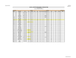

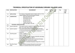


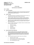
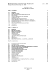


![010003E - [PROJECT.TOC] - TMG Construction Corporation](http://vs1.manualzilla.com/store/data/006000704_1-51daa2ac67e6ebfb9337b1b072f623df-150x150.png)