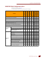
1
SNAP PAC BRAINS USER’S GUIDE
SNAP-PAC-EB1
SNAP-PAC-EB2
SNAP-PAC-EB1-FM
SNAP-PAC-EB2-FM
SNAP-PAC-EB1-W
SNAP-PAC-EB2-W
SNAP-PAC-SB1
SNAP-PAC-SB2
Form 1690-091022—October 2009
43044 Business Park Drive • Temecula • CA 92590-3614
Phone: 800-321-OPTO (6786) or 951-695-3000
Fax: 800-832-OPTO (6786) or 951-695-2712
www.opto22.com
Product Support Services
800-TEK-OPTO (835-6786) or 951-695-3080
Fax: 951-695-3017
Email: [email protected]
Web: support.opto22.com
SNAP PAC Brains User’s Guide
Form 1690-091022—October 2009
Copyright © 2007–2009 Opto 22.
All rights reserved.
Printed in the United States of America.
The information in this manual has been checked carefully and is believed to be accurate; however, Opto 22 assumes no
responsibility for possible inaccuracies or omissions. Specifications are subject to change without notice.
Opto 22 warrants all of its products to be free from defects in material or workmanship for 30 months from the
manufacturing date code. This warranty is limited to the original cost of the unit only and does not cover installation, labor, or
any other contingent costs. Opto 22 I/O modules and solid-state relays with date codes of 1/96 or later are guaranteed for life.
This lifetime warranty excludes reed relay, SNAP serial communication modules, SNAP PID modules, and modules that
contain mechanical contacts or switches. Opto 22 does not warrant any product, components, or parts not manufactured by
Opto 22; for these items, the warranty from the original manufacturer applies. These products include, but are not limited to,
OptoTerminal-G70, OptoTerminal-G75, and Sony Ericsson GT-48; see the product data sheet for specific warranty
information. Refer to Opto 22 form number 1042 for complete warranty information.
Wired+Wireless controllers and brains and N-TRON wireless access points are licensed under one or more of the following
patents: U.S. Patent No(s). 5282222, RE37802, 6963617; Canadian Patent No. 2064975; European Patent No. 1142245; French
Patent No. 1142245; British Patent No. 1142245; Japanese Patent No. 2002535925A; German Patent No. 60011224.
Cyrano, Opto 22 FactoryFloor, Optomux, and Pamux are registered trademarks of Opto 22. Generation 4, ioControl, ioDisplay,
ioManager, ioProject, ioUtilities, mistic, Nvio, Nvio.net Web Portal, OptoConnect, OptoControl, OptoDataLink, OptoDisplay,
OptoOPCServer, OptoScript, OptoServer, OptoTerminal, OptoUtilities, PAC Control, PAC Display, PAC Manager, PAC Project,
SNAP Ethernet I/O, SNAP I/O, SNAP OEM I/O, SNAP PAC System, SNAP Simple I/O, SNAP Ultimate I/O, and Wired+Wireless
are trademarks of Opto 22.
ActiveX, JScript, Microsoft, MS-DOS, VBScript, Visual Basic, Visual C++, Windows, and Windows Vista are either registered
trademarks or trademarks of Microsoft Corporation in the United States and other countries. Linux is a registered trademark of
Linus Torvalds. Unicenter is a registered trademark of Computer Associates International, Inc. ARCNET is a registered
trademark of Datapoint Corporation. Modbus is a registered trademark of Schneider Electric. Wiegand is a registered
trademark of Sensor Engineering Corporation. Nokia, Nokia M2M Platform, Nokia M2M Gateway Software, and Nokia 31 GSM
Connectivity Terminal are trademarks or registered trademarks of Nokia Corporation. Sony is a trademark of Sony Corporation.
Ericsson is a trademark of Telefonaktiebolaget LM Ericsson. CompactLogix, and RSLogix are trademarks of Rockwell
Automation. Allen-Bradley and ControlLogix are a registered trademarks of Rockwell Automation. CIP and EtherNet/IP are
trademarks of ODVA.
All other brand or product names are trademarks or registered trademarks of their respective companies or organizations.
ii
SNAP PAC Brains User’s Guide
Table of Contents
Chapter 1: Introduction . . . . . . . . . . . . . . . . . . . . . . . . . . . . . . . . . . . . . . . . . . . . . . . . . . 1
About SNAP PAC Brains. . . . . . . . . . . . . . . . . . . . . . . . . . . . . . . . . . . . . . . . . . . . . . . . . . . . . . . . . . . . . . . . . . . . . . 1
I/O Processing . . . . . . . . . . . . . . . . . . . . . . . . . . . . . . . . . . . . . . . . . . . . . . . . . . . . . . . . . . . . . . . . . . . . . . . . . 1
Communications . . . . . . . . . . . . . . . . . . . . . . . . . . . . . . . . . . . . . . . . . . . . . . . . . . . . . . . . . . . . . . . . . . . . . . . 2
Wired+Wireless Communication . . . . . . . . . . . . . . . . . . . . . . . . . . . . . . . . . . . . . . . . . . . . . . . . . . . . 2
PAC Project Software Suite . . . . . . . . . . . . . . . . . . . . . . . . . . . . . . . . . . . . . . . . . . . . . . . . . . . . . . . . . . 3
Other Communication Methods . . . . . . . . . . . . . . . . . . . . . . . . . . . . . . . . . . . . . . . . . . . . . . . . . . . . . 3
Custom Software . . . . . . . . . . . . . . . . . . . . . . . . . . . . . . . . . . . . . . . . . . . . . . . . . . . . . . . . . . . . . . . . . . 3
About this Guide. . . . . . . . . . . . . . . . . . . . . . . . . . . . . . . . . . . . . . . . . . . . . . . . . . . . . . . . . . . . . . . . . . . . . . . . . . . . 4
Other Documents You May Need . . . . . . . . . . . . . . . . . . . . . . . . . . . . . . . . . . . . . . . . . . . . . . . . . . . . . . . . . 4
For Help . . . . . . . . . . . . . . . . . . . . . . . . . . . . . . . . . . . . . . . . . . . . . . . . . . . . . . . . . . . . . . . . . . . . . . . . . . . . . . . . . . . 5
Chapter 2: Installing a SNAP PAC Brain . . . . . . . . . . . . . . . . . . . . . . . . . . . . . . . . . . . 7
What You Will Need. . . . . . . . . . . . . . . . . . . . . . . . . . . . . . . . . . . . . . . . . . . . . . . . . . . . . . . . . . . . . . . . . . . . . . . . . 7
Installing Software . . . . . . . . . . . . . . . . . . . . . . . . . . . . . . . . . . . . . . . . . . . . . . . . . . . . . . . . . . . . . . . . . . . . . . . . . . 8
Installing Hardware . . . . . . . . . . . . . . . . . . . . . . . . . . . . . . . . . . . . . . . . . . . . . . . . . . . . . . . . . . . . . . . . . . . . . . . . . 8
Installing Modules on the Rack . . . . . . . . . . . . . . . . . . . . . . . . . . . . . . . . . . . . . . . . . . . . . . . . . . . . . . . . . . . 8
Removing a Module . . . . . . . . . . . . . . . . . . . . . . . . . . . . . . . . . . . . . . . . . . . . . . . . . . . . . . . . . . . . . . . . 9
Installing the Brain . . . . . . . . . . . . . . . . . . . . . . . . . . . . . . . . . . . . . . . . . . . . . . . . . . . . . . . . . . . . . . . . . . . . 10
Setting Up Ethernet Networking . . . . . . . . . . . . . . . . . . . . . . . . . . . . . . . . . . . . . . . . . . . . . . . . . . . . . . . . . 10
Setting Up Serial Networking . . . . . . . . . . . . . . . . . . . . . . . . . . . . . . . . . . . . . . . . . . . . . . . . . . . . . . . . . . . 11
Serial Wiring Diagrams . . . . . . . . . . . . . . . . . . . . . . . . . . . . . . . . . . . . . . . . . . . . . . . . . . . . . . . . . . . . 12
What’s Next? . . . . . . . . . . . . . . . . . . . . . . . . . . . . . . . . . . . . . . . . . . . . . . . . . . . . . . . . . . . . . . . . . . . . . . . . . . . . . 15
Chapter 3: System Architecture . . . . . . . . . . . . . . . . . . . . . . . . . . . . . . . . . . . . . . . . .17
Communication Options. . . . . . . . . . . . . . . . . . . . . . . . . . . . . . . . . . . . . . . . . . . . . . . . . . . . . . . . . . . . . . . . . . . 17
SNAP PAC Ethernet Brains . . . . . . . . . . . . . . . . . . . . . . . . . . . . . . . . . . . . . . . . . . . . . . . . . . . . . . . . . . . . . . 17
SNAP PAC Brains User’s Guide
iii
iii
Simultaneous Communication . . . . . . . . . . . . . . . . . . . . . . . . . . . . . . . . . . . . . . . . . . . . . . . . . . . . . .18
SNAP PAC Serial Brains . . . . . . . . . . . . . . . . . . . . . . . . . . . . . . . . . . . . . . . . . . . . . . . . . . . . . . . . . . . . . . . . .19
Accessing SNAP PAC Brains Over the Internet . . . . . . . . . . . . . . . . . . . . . . . . . . . . . . . . . . . . . . . . . . . . .19
Choosing Communication Methods . . . . . . . . . . . . . . . . . . . . . . . . . . . . . . . . . . . . . . . . . . . . . . . . . . . . . .20
System Architecture . . . . . . . . . . . . . . . . . . . . . . . . . . . . . . . . . . . . . . . . . . . . . . . . . . . . . . . . . . . . . . . . . . . . . . . 21
SNAP PAC Brains as Part of a Distributed SNAP PAC System . . . . . . . . . . . . . . . . . . . . . . . . . . . . . . . . .21
SNAP PAC Wired+Wireless Brains . . . . . . . . . . . . . . . . . . . . . . . . . . . . . . . . . . . . . . . . . . . . . . . . . . . . . . .22
SNAP PAC Ethernet Brain in an Allen-Bradley Logix System . . . . . . . . . . . . . . . . . . . . . . . . . . . . . . . . .23
SNAP PAC Ethernet Brain as an Independent I/O Processor . . . . . . . . . . . . . . . . . . . . . . . . . . . . . . . . . .24
SNAP PAC Serial Brain as an Independent I/O Processor . . . . . . . . . . . . . . . . . . . . . . . . . . . . . . . . . . . .25
Ethernet Networking . . . . . . . . . . . . . . . . . . . . . . . . . . . . . . . . . . . . . . . . . . . . . . . . . . . . . . . . . . . . . . . . . . . . . . 26
Connecting Directly to a PC or Controller . . . . . . . . . . . . . . . . . . . . . . . . . . . . . . . . . . . . . . . . . . . . . . . . . .26
Attaching to an Existing Ethernet Network . . . . . . . . . . . . . . . . . . . . . . . . . . . . . . . . . . . . . . . . . . . . . . . .26
Developing an Independent Ethernet Network . . . . . . . . . . . . . . . . . . . . . . . . . . . . . . . . . . . . . . . . . . . .27
Using the Brain in a Wireless LAN . . . . . . . . . . . . . . . . . . . . . . . . . . . . . . . . . . . . . . . . . . . . . . . . . . . . . . . .27
Using SNAP PAC Ethernet Brain Wired Network Interfaces . . . . . . . . . . . . . . . . . . . . . . . . . . . . . . . . . .28
Correct Connections for Daisy-Chaining . . . . . . . . . . . . . . . . . . . . . . . . . . . . . . . . . . . . . . . . . . . . . .29
Incorrect Network Connections . . . . . . . . . . . . . . . . . . . . . . . . . . . . . . . . . . . . . . . . . . . . . . . . . . . . . .29
Specifications . . . . . . . . . . . . . . . . . . . . . . . . . . . . . . . . . . . . . . . . . . . . . . . . . . . . . . . . . . . . . . . . . . . . . . . . . . . . . 30
Specifications . . . . . . . . . . . . . . . . . . . . . . . . . . . . . . . . . . . . . . . . . . . . . . . . . . . . . . . . . . . . . . . . . . . . . . . . .30
LEDs and Network Interfaces—Wired Ethernet Brains . . . . . . . . . . . . . . . . . . . . . . . . . . . . . . . . . . . . . .31
LEDs and Network Interfaces—Wired+Wireless Brains . . . . . . . . . . . . . . . . . . . . . . . . . . . . . . . . . . . .31
LEDs and Network Interfaces—Serial Brains . . . . . . . . . . . . . . . . . . . . . . . . . . . . . . . . . . . . . . . . . . . . . .32
SNAP PAC Brain Comparison Chart . . . . . . . . . . . . . . . . . . . . . . . . . . . . . . . . . . . . . . . . . . . . . . . . . . . . . . . . . . 33
Feature Descriptions . . . . . . . . . . . . . . . . . . . . . . . . . . . . . . . . . . . . . . . . . . . . . . . . . . . . . . . . . . . . . . . . . . .35
Chapter 4: Maintenance and Troubleshooting . . . . . . . . . . . . . . . . . . . . . . . . . . . 39
Introduction . . . . . . . . . . . . . . . . . . . . . . . . . . . . . . . . . . . . . . . . . . . . . . . . . . . . . . . . . . . . . . . . . . . . . . . . . . . . . . 39
Maintaining the SNAP PAC Brain . . . . . . . . . . . . . . . . . . . . . . . . . . . . . . . . . . . . . . . . . . . . . . . . . . . . . . . . . . . . 39
Backup Battery . . . . . . . . . . . . . . . . . . . . . . . . . . . . . . . . . . . . . . . . . . . . . . . . . . . . . . . . . . . . . . . . . . . . . . . .39
Changing the Ethernet Brain’s IP Address . . . . . . . . . . . . . . . . . . . . . . . . . . . . . . . . . . . . . . . . . . . . . . . . .40
Resetting the Brain . . . . . . . . . . . . . . . . . . . . . . . . . . . . . . . . . . . . . . . . . . . . . . . . . . . . . . . . . . . . . . . . . . . . .40
Loading New Firmware . . . . . . . . . . . . . . . . . . . . . . . . . . . . . . . . . . . . . . . . . . . . . . . . . . . . . . . . . . . . . . . . .41
Setting Time and Date . . . . . . . . . . . . . . . . . . . . . . . . . . . . . . . . . . . . . . . . . . . . . . . . . . . . . . . . . . . . . . . . . .41
Blink Codes . . . . . . . . . . . . . . . . . . . . . . . . . . . . . . . . . . . . . . . . . . . . . . . . . . . . . . . . . . . . . . . . . . . . . . . . . . .41
Self-Test LED Sequence at Startup . . . . . . . . . . . . . . . . . . . . . . . . . . . . . . . . . . . . . . . . . . . . . . . . . . .41
Normal LED Behavior: MS, NS, and WLAN LEDs . . . . . . . . . . . . . . . . . . . . . . . . . . . . . . . . . . . . . . .41
iv
SNAP PAC Brains User’s Guide
STAT LED—Green . . . . . . . . . . . . . . . . . . . . . . . . . . . . . . . . . . . . . . . . . . . . . . . . . . . . . . . . . . . . . . . . 42
STAT LED—Orange . . . . . . . . . . . . . . . . . . . . . . . . . . . . . . . . . . . . . . . . . . . . . . . . . . . . . . . . . . . . . . . 42
STAT LED—Red and Green . . . . . . . . . . . . . . . . . . . . . . . . . . . . . . . . . . . . . . . . . . . . . . . . . . . . . . . . 42
STAT LED—Red . . . . . . . . . . . . . . . . . . . . . . . . . . . . . . . . . . . . . . . . . . . . . . . . . . . . . . . . . . . . . . . . . . 43
Getting Device and Firmware Information . . . . . . . . . . . . . . . . . . . . . . . . . . . . . . . . . . . . . . . . . . . . . . . . . . . 43
Troubleshooting SNAP PAC Brains . . . . . . . . . . . . . . . . . . . . . . . . . . . . . . . . . . . . . . . . . . . . . . . . . . . . . . . . . . 46
Communicating with a Wired EB Brain . . . . . . . . . . . . . . . . . . . . . . . . . . . . . . . . . . . . . . . . . . . . . . . . . . . 46
Pinging the Brain . . . . . . . . . . . . . . . . . . . . . . . . . . . . . . . . . . . . . . . . . . . . . . . . . . . . . . . . . . . . . . . . . 47
Accessing the Ethernet Brain with PAC Manager . . . . . . . . . . . . . . . . . . . . . . . . . . . . . . . . . . . . . . 47
Solving Ethernet Network Problems . . . . . . . . . . . . . . . . . . . . . . . . . . . . . . . . . . . . . . . . . . . . . . . . . 49
Communicating with the SB Brain . . . . . . . . . . . . . . . . . . . . . . . . . . . . . . . . . . . . . . . . . . . . . . . . . . . . . . . 50
Turning on Communication Error Blink Codes (Serial Brain) . . . . . . . . . . . . . . . . . . . . . . . . . . . . 50
Additional Troubleshooting Tools . . . . . . . . . . . . . . . . . . . . . . . . . . . . . . . . . . . . . . . . . . . . . . . . . . . . . . . . . . . 52
Making Sure the Brain is in Normal Mode . . . . . . . . . . . . . . . . . . . . . . . . . . . . . . . . . . . . . . . . . . . . . . . . . 52
TCP Settings (Ethernet Brains) . . . . . . . . . . . . . . . . . . . . . . . . . . . . . . . . . . . . . . . . . . . . . . . . . . . . . . . . . . 52
Appendix A: Serial Cables and Addressing . . . . . . . . . . . . . . . . . . . . . . . . . . . . . .55
Serial Cables. . . . . . . . . . . . . . . . . . . . . . . . . . . . . . . . . . . . . . . . . . . . . . . . . . . . . . . . . . . . . . . . . . . . . . . . . . . . . . 55
Address Table . . . . . . . . . . . . . . . . . . . . . . . . . . . . . . . . . . . . . . . . . . . . . . . . . . . . . . . . . . . . . . . . . . . . . . . . . . . . 55
Index . . . . . . . . . . . . . . . . . . . . . . . . . . . . . . . . . . . . . . . . . . . . . . . . . . . . . . . . . . . . . . . . . .57
SNAP PAC Brains User’s Guide
vv
vi
SNAP PAC Brains User’s Guide
Chapter 1
1: Introduction
About SNAP PAC Brains
SNAP PAC brains are powerful and versatile I/O and network communications processors for your
SNAP PAC System™. These brains are designed primarily to work in distributed systems controlled by
a SNAP PAC programmable automation controller, but SNAP PAC Ethernet brains can also be used as
intelligent remote I/O in an Allen-Bradley® Logix-based PLC system.
All SNAP PAC brains provide local intelligence that frees the controller for supervisory tasks. SNAP
PAC brains can also be used independently for standalone I/O processing and communication.
SNAP PAC brains use either Ethernet networks or serial networks.
•
The Ethernet Brains—SNAP-PAC-EB1 and SNAP-PAC-EB2—share the same functions
and features except that the SNAP-PAC-EB1 provides high-speed digital functions. The
SNAP-PAC-EB2 does not offer high-speed digital. SNAP-PAC-EB1-FM and
SNAP-PAC-EB2-FM are Factory Mutual-approved versions of these two brains.
The SNAP-PAC-R1-W and SNAP-PAC-R2-W are Wired+Wireless® models, which retain all
the same features and add a wireless LAN interface. For more information on Wired+Wireless,
see page 2.
•
The two Serial Brains—SNAP-PAC-SB1 and SNAP-PAC-SB2—are like each other in their
functions and features except that the SNAP-PAC-SB1 provides high-speed digital functions.
The SNAP-PAC-SB2 does not offer high-speed digital.
Because the EB brains and SB brains run on different networks, some of their features differ. For a
comparison of brain features, see page 33.
I/O Processing
As an I/O processor, the SNAP PAC brain provides the local intelligence to independently handle
functions such as latching, counting, thermocouple linearization, watchdog timers, and PID loop
control. These functions continue to work on the brain even if communication with the controller is
lost.
Each SNAP PAC brain mounts on a SNAP PAC rack with up to 4, 8, 12, or 16 SNAP I/O™ modules. Each
module provides from 1 to 32 I/O points, depending on the module.
SNAP PAC Brains User’s Guide
11
ABOUT SNAP PAC BRAINS
SNAP PAC Ethernet brains, both wired and wired+wireless, support all the SNAP I/O analog,
digital, serial, and special-purpose input and output modules available on the Opto 22 website.
SNAP PAC Serial brains support all analog and digital SNAP I/O modules (including high-density).
All SNAP I/O modules can be mixed on the same mounting rack and placed in any position on the
rack, to accommodate the required mix of signals at any location. For more information on
mounting racks, see Opto 22 form #1684, the SNAP PAC Racks Data Sheet. For more information on
I/O modules, visit our website at www.opto22.com.
Communications
In addition to I/O processing, SNAP PAC brains provide communication through a choice of
networks:
•
Wired Ethernet—SNAP-PAC-EB1, SNAP-PAC-EB1-FM, SNAP-PAC-EB2, and
SNAP-PAC-EB2-FM brains communicate over a standard 10/100 Mbps Ethernet network.
Each brain is equipped with two switched Ethernet network interfaces. Because these
interfaces share a single IP address and act just like an Ethernet switch, SNAP PAC brains can be
installed in a multi-drop (daisy-chain) configuration, extending the control network without
the expense of additional Ethernet network hardware. SNAP PAC brains can also be installed in
a star configuration using standard, off-the-shelf Ethernet network components.
•
Wired+Wireless Ethernet—SNAP-PAC-EB1-W and SNAP-PAC-EB2-W, like their wired
counterparts, communicate over a standard 10/100 Mbps Ethernet network and are equipped
with two switched Ethernet network interfaces. In addition, they have a wireless LAN interface,
which is a separate interface card with its own IP address. See “Wired+Wireless
Communication,” below, for more information.
•
Serial—SNAP-PAC-SB1 and SNAP-PAC-SB2 brains communicate over a standard RS-485
network, either two-wire or four-wire, using a binary protocol. Baud rates from 300 to
230,400 bps are supported. There are 256 possible multidrop addresses.
Wired+Wireless Communication
SNAP-PAC-EB1-W and SNAP-PAC-EB2-W brains offer a choice of networks. They can be used
on a wired network, on a wireless LAN, or on both at the same time. For flexibility in designing
your wireless network, 802.11a, b, and g standards are supported.
Wired+Wireless EB brains can be used with Wired+Wireless SNAP PAC S-series and R-series
controllers and a variety of wireless switches and other infrastructure hardware. For the
best security, the 802.11i WPA2/AES standard is supported, while older WPA and
WEP security standards are included for backwards compatibility.
Because wireless functionality is in the brain itself, no additional parts are
required for wireless I/O processing or communication. All SNAP PAC racks
and SNAP I/O modules can be used either wired or wirelessly. You can
switch from one network to the other without reconfiguring I/O or
changing field wiring. All features work the same on both networks. See
the feature chart on page 33.
2
SNAP PAC Brains User’s Guide
CHAPTER 1: INTRODUCTION
PAC Project Software Suite
SNAP PAC brains are most often used as part of a SNAP PAC System, communicating primarily with a
SNAP PAC programmable automation controller. SNAP PAC R-series controllers can communicate
with Ethernet brains only; SNAP PAC S-series controllers can communicate with both serial and
Ethernet brains at the same time. The controller runs a control program, called a strategy, which you
develop using PAC Project™ software.
The PAC Project software suite comes in two forms, Basic and Professional:
•
PAC Project Basic, which is included in the purchase of a SNAP PAC controller, consists of
control programming, human-machine interface (HMI) creation, and configuration software.
•
PAC Project Professional is available for purchase and adds OptoOPCServer™ for OPC
communications, OptoDataLink™ for database connectivity, and additional features.
For more information about PAC Project, see form #1699, the PAC Project Data Sheet, available on our
website, www.opto22.com.
Other Communication Methods
While most customers use the PAC Project software suite for control, monitoring, and data
acquisition, SNAP PAC brains can communicate using other several other methods.
SNAP PAC EB brains can be used as intelligent remote I/O in an Allen-Bradley® RSLogix® PLC system,
and both EB and SB brains can be used as standalone I/O and communications processors for
PC-based I/O.
SNAP PAC Ethernet brains support communication using multiple protocols running
simultaneously over Ethernet. You can communicate with SNAP PAC Ethernet brains using
EtherNet™/IP for Allen-Bradley systems, Modbus®/TCP, SNMP for network management, FTP for the
brain’s built-in file system, SMTP (email client), and Opto 22’s own memory-mapped OptoMMP
protocol. Communication with OPC 2.0-compliant clients is available through OptoOPCServer.
•
For EtherNet/IP, see Opto 22 form #1770, the EtherNet/IP for SNAP PAC Protocol Guide.
•
For Modbus/TCP, see form #1678, the Modbus/TCP Protocol Guide.
•
For SNMP, FTP, and SMTP, see form #1704, the PAC Manager User’s Guide.
•
For OptoMMP, see form #1465, the OptoMMP Protocol Guide.
•
For OPC connectivity, use OptoOPCServer, available either as part of PAC Project Professional or
for separate purchase. See our website for more information.
SNAP PAC serial brains support communication using OptoMMP, Opto 22’s open and
documented memory-mapped protocol. See form #1465, the OptoMMP Protocol Guide.
Custom Software
If you are not using PAC Project and want to develop custom software to communicate with the
brain, the OptoMMP Communication Toolkit is available for free on our website,
www.opto22.com. The toolkit includes ActiveX components and C++ classes, so you can use
programming tools such as Visual Basic or Visual C++ to communicate with the brain. See form
#1465, the OptoMMP Protocol Guide, for more information.
SNAP PAC Brains User’s Guide
33
ABOUT THIS GUIDE
About this Guide
This guide shows you how to install and use SNAP PAC brains. This guide assumes that you are
already familiar with networking (serial, wired Ethernet, or wireless LAN) for the types of brains you’ll
be using. If you are not familiar with these subjects, we strongly suggest you consult commercially
available resources to learn about them before attempting to install or use SNAP PAC brains.
The following sections are included in this user’s guide:
Chapter 1: Introduction—information about the guide and how to reach Opto 22 Product
Support.
Chapter 2: Installing a SNAP PAC Brain—quick-start steps to get SNAP PAC brains up and
running quickly.
Chapter 3: System Architecture—conceptual information on networking and communicating
with SNAP PAC brains, and brain specifications.
Chapter 4: Maintenance and Troubleshooting—changing IP addresses, resetting the brain to
factory defaults, and upgrading firmware; blink codes and other troubleshooting assistance.
Appendix A: Serial Cables and Addressing—for SNAP PAC serial brains, shows how to set
address switches for all possible brain addresses.
Other Documents You May Need
See the following additional guides for the information listed. All guides are available on the Opto 22
website, www.opto22.com; some are included on the CD that came with the SNAP PAC brain.
For this information
Assigning IP address, loading new firmware, etc.
See this guide
PAC Manager User’s Guide
1704
PAC Control User’s Guide
1700
PAC Control Command Reference
1701
PAC Control Commands Quick Reference Card
1703
Communicating with SNAP PAC brains using
OPC*
OptoOPCServer User’s Guide
1439
Connecting the SNAP PAC System with databases
OptoDataLink User’s Guide
1705
Communicating between SNAP PAC Ethernet
brains and Allen-Bradley Logix PLCs
EtherNet/IP for SNAP PAC Protocol Guide
1770
Communicating with SNAP PAC Ethernet brains
using Modbus/TCP
Modbus/TCP Protocol Guide
1678
Programming your own applications for SNAP PAC
brains using the OptoMMP Communication Toolkit
or the OptoMMP memory-mapped protocol
OptoMMP Protocol Guide
1465
Designing flowchart-based control programs for
the system (requires a SNAP PAC S-series or
R-series industrial controller)
*OptoOPCServer communication with SNAP PAC Serial brains requires a SNAP PAC controller.
4
Form #
SNAP PAC Brains User’s Guide
CHAPTER 1: INTRODUCTION
For Help
If you have problems installing or using SNAP PAC brains and cannot find the help you need in this
guide or on our website, contact Opto 22 Product Support.
Phone:
800-TEK-OPTO (835-6786)
951-695-3080
(Hours are Monday through Friday,
7 a.m. to 5 p.m. Pacific Time)
Fax:
951-695-3017
Email:
[email protected]
Opto 22 website:
www.opto22.com
NOTE: Email messages and
phone calls to Opto 22
Product Support are
grouped together and
answered in the order
received.
When calling for technical support, be prepared to provide the following information about your
system to the Product Support engineer:
•
Software and version being used
•
Brain and controller firmware version (as applicable)
•
PC configuration (type of processor, speed, memory, and operating system)
•
A complete description of your hardware and operating systems, including:
– loader and firmware versions for the brain, and date code (available through PAC Manager;
see page 54.)
– for an Ethernet network, IP addresses and subnet masks for devices on the system
– for a serial network, addressing and communication parameters
– type of power supply
– third-party devices installed (for example, barcode readers)
•
Specific error messages seen
SNAP PAC Brains User’s Guide
55
FOR HELP
6
SNAP PAC Brains User’s Guide
Chapter 2
2: Installing a SNAP PAC Brain
If you already know how you will use the SNAP PAC brain and want to get it running quickly, follow
the sections in this chapter.
To learn about communication options and networking, start on page 17. Specifications are listed on
page 30.
What You Will Need
You’ll need the following items to install a SNAP PAC brain:
•
PC running Microsoft® Windows® 2000, XP, or Vista.
•
For an Ethernet connection, the PC also needs a 10/100 MB Ethernet adapter card, the
TCP/IP protocol installed, and a valid IP address, on the same subnet as the brain. (For more
information, see “Ethernet Networking” on page 26.) In addition, you need a standard Ethernet
cable for direct connection to the PC (recommended), or an available connection to a standard
10BASE-T or 100BASE-TX Ethernet network.
NOTE: Wired+Wireless models must be initially configured using a wired interface. Once IP addresses
and wireless communication parameters are set, the brain can be used wirelessly.
•
For a serial connection, RS-485 (2-wire or 4-wire) connection to a SNAP PAC S-series
controller or to a PC with an Opto 22 PCI-AC48 adapter card. (See “Setting Up Serial
Networking” on page 11 for more information and wiring diagrams.)
•
SNAP PAC brain (See page 33 for a chart comparing models.)
•
SNAP PAC mounting rack and SNAP I/O modules chosen for your application.
•
A SNAP-PS5 or SNAP-PS5U power supply or other 5 VDC power supply (-0/+0.1 VDC at 4.0 A)
applied to the rack. (Additional power may be required for SNAP I/O modules depending on
the number and type of modules used. See the module data sheets on our website,
www.opto22.com, for information.)
SNAP PAC Brains User’s Guide
77
INSTALLING SOFTWARE
Installing Software
In your CD-ROM drive, insert the CD that came with the brain. The installation wizard should start
automatically. If it doesn’t, use Windows Explorer to navigate to your CD-ROM drive and then
double-click setup.exe. Follow directions to install the software.
Installing Hardware
Assemble the rack and power supply according to the directions that came with them.
Installing Modules on the Rack
Modules snap into place in the row of connectors on the rack. Each module connector has a number.
Ethernet-based brains, both standard wired and Wired+Wireless models) support all SNAP I/O
modules. Serial-based brains support all SNAP I/O analog and digital modules (including
high-density modules).
NOTE: Any type of module can be placed in any position on the rack. Check module data sheets for power
requirements and any quantity limitations. See the chart on page 33 for brain compatibility.
1. Place the rack so that the module connector numbers are right-side up, with zero on the left.
Brain connector
Module
Module connectors
position zero
Retention bar
2. Position the module over the module connector, aligning the small slot at the base of the
module with the retention bar on the rack.
8
SNAP PAC Brains User’s Guide
CHAPTER 2: INSTALLING A SNAP PAC BRAIN
3. With the module correctly aligned
over the connector, push on the
module to snap it into place.
Module keys
When positioning modules next to
each other, be sure to align the male
and female module keys (shown in
the detailed view in the illustration at
right) before snapping a module into
position.
Modules snap securely into place and
require a special tool (provided) for
removal. To remove a module, see
page 9.
4. (Optional) Use standard 4-40 x 1/2
truss-head Phillips hold-down screws
to secure both sides of each module.
Optional holddown screws
CAUTION: Do not over-tighten screws.
5. Plug the wiring connector into each module to attach modules to the devices they monitor.
Wiring diagrams are in the module’s data sheet.
Removing a Module
If you need to remove a module, follow these
steps.
1. If the modules are held in place with
screws, remove them.
2. Holding the SNAP module tool
(provided) as shown in the illustration at
right, insert it into the notch at the base
of the module.
3. Squeeze the module tool against the
module to open the release latch, and
pull straight up on the module to remove
it.
4. Continue with “Installing the Brain” on
page 10.
SNAP PAC Brains User’s Guide
99
INSTALLING HARDWARE
Installing the Brain
1. Remove the brain from its packaging.
2. Turn off power to the rack assembly.
3. Align the brain connector with the mating
connector on the mounting rack.
4. Seat the brain onto the connector and use
the hold-down screw to secure the brain in
position. Do not overtighten.
5. To attach network cabling and configure
addressing, skip to one of the following:
– “Setting Up Ethernet Networking” on
page 10.
– “Setting Up Serial Networking” on
page 11.
Setting Up Ethernet Networking
NOTE: Wired+Wireless models must be initially configured using a wired interface.
1. For an Ethernet brain (either a standard wired or Wired+Wireless model), use Category 5 or
superior solid unshielded twisted-pair cable to connect the brain in one of the following ways:
– (Recommended for initial configuration) Connect to a PC directly, using a standard Ethernet
cable.
– Connect to a standard 10BASE-T or 100BASE-TX Ethernet network that has a PC on the
same subnet as the brain and does NOT have a Dynamic Host Configuration Protocol
(DHCP) server.
Maximum cable or segment length is 100 meters; minimum cable length is one meter.
NOTE: When connecting the contoller to a managed switch, make sure the managed switch's port
configuration is set to Auto for the Duplex setting and Auto for the Speed setting.
2. Before turning on power to the rack, follow instructions in Opto 22 form #1704, the PAC
Manager User’s Guide, to assign an IP address to the brain. Exception: If you are using the brain
with an Allen-Bradley Logix system, follow instructions in form #1770, the EtherNet/IP for SNAP
PAC Protocol Guide.
These guides are in Adobe Acrobat PDF format on the CD that came with the brain and are also
available from our website, www.opto22.com.
10
SNAP PAC Brains User’s Guide
CHAPTER 2: INSTALLING A SNAP PAC BRAIN
Setting Up Serial Networking
The serial brain can be connected to a SNAP
PAC S-series controller or to a PC equipped
with an Opto 22 PCI-AC48 adapter card,
which provides an RS-485 serial converter.
SNAP PAC serial brain—top view
Baud rate
switch
Pin 1
TX/RX LED
If you are using PAC Control software,
connect the brain to an S-series controller.
Follow the diagram at right and the steps
below to set up serial networking.
Serial
connector
Reset switch
1. Attach an RS-485 serial cable to the
serial port. (See Appendix A: Serial
Cables and Addressing for cable
recommendations).
2. Follow the wiring diagrams beginning
on page 12 for the serial network.
Termination
switches
Address upper
Address lower
Reserved LED
STAT LED
3. Rotate the baud rate switch to set the
desired baud rate, as follows:
Switch
position
Baud rate
Switch
position
Baud Rate Switch
(Reserved)
F
4800 bps
7
7 8 9
230400 bps
E
2400 bps
6
115200 bps
D
1200 bps
5
76800 bps
C
600 bps
4
57600 bps
B
300 bps
3
38400 bps
A
(Reserved)
2
19200 bps
9
(Reserved)
1
9600 bps
8
(Reserved)
0
2
B CD E
3 4 5 6
A
Baud rate
F 0 1
4. Use the three tiny termination switches to set termination:
NOTE: Bias on a SNAP PAC SB brain is always ON.
(Switch 3 is reserved.)
123
– For full-duplex termination (4-wire 485), move switch 1 to ON
and switch 2 to ON (illustrated at right)
ON
– For half-duplex termination (2-wire 485), move switch 1 (TX/RX)
to ON and switch 2 (RX) to OFF.
IRQ
RX
TX/RX
5. Use the two rotary address switches to set the unit’s address.
There are 256 possible addresses, 0–255. See Appendix A: Serial Cables and Addressing for a
table of addresses and how to set them using the two 16-position rotary address switches.
SNAP PAC Brains User’s Guide
11
11
INSTALLING HARDWARE
Serial Wiring Diagrams
Wiring a SNAP PAC SB-Series Brain to a SNAP-PAC-S1 Controller
Two-wire
Pin 1
TX/RX +
TX/RX –
COM
TX/RX +
TX/RX –
COM
TX/RX +
TX/RX –
COM
2-wire, middle of link
All switches OFF
2-wire termination, end of link
Switches 3 & 2 OFF
Switch 1 ON
12
SNAP PAC Brains User’s Guide
123
ON
123
ON
Earth GND
CHAPTER 2: INSTALLING A SNAP PAC BRAIN
Wiring a SNAP PAC SB-Series Brain to a SNAP-PAC-S2 Controller
Two-wire
Pin 1
TX/RX +
TX/RX –
COM
TX/RX +
TX/RX –
COM
TX/RX +
TX/RX –
COM
2-wire, middle of link.
All switches OFF
2-wire termination, end of link
Switches 3 & 2 OFF
Switch 1 ON
123
ON
123
ON
Earth GND
Four-wire
RX +
RX –
COM
TX/RX +
TX/RX –
TX/RX +
TX/RX COM
RX +
RX -
4-wire, middle of link
All switches OFF
123
Earth GND
ON
TX/RX +
TX/RX COM
RX +
RX -
123
4
5
3
1
2
ON
NOTE: The connector pins
on an actual SNAP-PAC-S2
are in a different order than
shown here.
4-wire termination, end of link
Switch 3 OFF
Switches 2 & 1 ON
SNAP PAC Brains User’s Guide
13
13
INSTALLING HARDWARE
Wiring to a PCI-AC48 Adapter Card in a PC
NOTE: Check the default termination and bias on the PCI-AC48 and make certain they are set
appropriately for the network.
Two-wire
PCI-AC48 adapter card in PC
Pin 1
TX/RX +
TX/RX –
COM
TX/RX +
TX/RX –
COM
2-wire, middle of link
All switches OFF
2-wire termination, end of link
Switches 3 & 2 OFF
Switch 1 ON
123
ON
123
ON
Earth GND
Four-wire
PCI-AC48 adapter card in PC
Pin 1
TX/RX +
TX/RX –
COM
RX +
RX –
TX/RX +
TX/RX –
COM
RX +
RX –
4-wire, middle of link
All switches OFF
4-wire termination, end of link
Switch 3 OFF
Switches 2 & 1 ON
14
SNAP PAC Brains User’s Guide
123
ON
123
ON
Earth GND
CHAPTER 2: INSTALLING A SNAP PAC BRAIN
What’s Next?
To start configuring I/O points, see one of the following:
•
If you are using PAC Control software, follow instructions in the PAC Control User’s Guide, form
#1700.
•
If you are using the brain in an A-B RSLogix system, follow configuration steps in the EtherNet/IP
for SNAP PAC Protocol Guide
•
If you are not using PAC Control or RSLogix, follow instructions in the PAC Manager User’s Guide.
To learn more about SNAP PAC brain capabilities and network options, see Chapter 3: System
Architecture. If you are planning to install multiple brains in a daisy-chain configuration, see “Using
SNAP PAC Ethernet Brain Wired Network Interfaces” on page 28.
To use OLE for process control (OPC) with SNAP PAC brains, purchase the OptoOPCServer and see
Opto 22 form #1439, the OptoOPCServer User’s Guide.
To communicate with SNAP PAC brains using Modbus/TCP, see form #1678, the Modbus/TCP Protocol
Guide.
To program your own applications to communicate with the SNAP PAC brain, see Opto 22 form
#1465, the OptoMMP Protocol Guide.
SNAP PAC Brains User’s Guide
15
15
WHAT’S NEXT?
16
SNAP PAC Brains User’s Guide
Chapter 3
3: System Architecture
This chapter explains how to use SNAP PAC brains on an Ethernet or serial network and how to
communicate with them. It includes information on:
Communication options
See below
System architecture
See page 21
Networking
See page 26
Specifications and feature comparison charts
See page 30
Communication Options
SNAP PAC brains communicate over Ethernet or serial.
•
SNAP PAC EB brains communicate over an Ethernet network (all part numbers containing EB).
See the following section for more information.
•
SNAP PAC SB brains communicate over a serial network (part numbers SNAP-PAC-SB1 and
SNAP-PAC-SB2). See page 19.
SNAP PAC Ethernet Brains
SNAP PAC Ethernet-based brains communicate using TCP/IP or UDP/IP over a wired or wireless
network.
Physical Layer—SNAP PAC EB brains communicate over a 10- or 100-Mbps wired Ethernet link.
Wired+Wireless brains can communicate over a 10/100 Mbps wired link, a wireless LAN, or both at
the same time (since the wireless LAN interface has a separate IP address).
Transport Layer—The key to the SNAP PAC brain‘s communication flexibility is the transport layer,
Internet Protocol (IP). Both the Transmission Control Protocol (TCP) and the User Datagram Protocol
(UDP) are used with IP.
Application Layer—Because SNAP PAC brains use standard IP for the transport layer, many
communication options are possible in the application layer. After the I/O unit is installed and has an
IP address assigned (see page 10), you can communicate with it using the following methods:
SNAP PAC Brains User’s Guide
17
17
COMMUNICATION OPTIONS
•
PAC Control strategies running on a SNAP PAC controller can configure, read, and write to I/O
points on SNAP PAC brains.
•
PAC Manager software, in addition to its use for assigning IP addresses, can also be used to
configure I/O points and features, and to perform onetime reads and writes.
•
EtherNet/IP provides communication with Allen-Bradley ControlLogix® and CompactLogix™
PLC systems and other systems using the EtherNet/IP protocol. Both implicit and explicit
messaging are supported.
•
Modbus/TCP provides a direct connection with Modbus/TCP hardware or software or
third-party software applications, which can read or write to I/O points on SNAP PAC brains.
•
OPC (OLE for Process Control) uses OptoOPCServer to serve data to any OPC 2.0-compliant
application, such as an HMI, which can also read or write to I/O points. OptoOPCServer can be
purchased separately or as part of the PAC Project Professional software suite.
•
OptoDataLink exchanges I/O point data with ODBC-compliant databases, including Microsoft
SQL Server, Microsoft Access, MySQL, and others. OptoDataLink can be purchased separately or
as part of PAC Project Professional.
•
SMTP (Simple Mail Transfer Protocol) connects a SNAP PAC brain with corporate email servers,
so employees can be emailed or paged if there’s a problem on devices attached to the brain.
•
SNMP (Simple Network Management Protocol) makes it possible to monitor devices attached
to SNAP PAC brains just as you would any computer or server on the Ethernet network, using an
SNMP-based enterprise management system such as Computer Associates’ Unicenter®,
Hewlett-Packard’s OpenView®, or IBM’s Tivoli®. When a monitored event occurs, such as a door
left open or a pressure level too high, the brain sends an SNMP trap to the management system
(compatible with SNMP v2.0c using brain firmware 8.2a or higher).
•
FTP (File Transfer Protocol) can be used to transfer files and data to and from the SNAP PAC
brain, whether to custom applications, enterprise databases, or any file system.
•
Custom software applications are easy to develop using our OptoMMP Communication
Toolkit with ActiveX components and C++ classes. They use the OptoMMP protocol, an IEEE
1394-based protocol, to read and write to SNAP PAC brains. For developers not using Microsoft
Windows, our OptoMMP protocol is open and documented.
Simultaneous Communication
The SNAP PAC Ethernet brain can communicate simultaneously using all of the methods listed above.
The reason lies in the nature of IP.
In serial communication, a single data request is sent by one device to another. The first device must
wait for a response before any additional communication can be carried out. IP, however, can
establish multiple simultaneous sessions, so many data requests can be sent at once without waiting
for any individual response. Each request gets a response, but the link isn’t idle while waiting for
responses.
In addition, IP can simultaneously handle multiple requests from multiple devices. A PC can
communicate with all SNAP PAC brains and controllers on the same network—all at the same
time—and multiple PCs can communicate with one SNAP PAC device at the same time.
18
SNAP PAC Brains User’s Guide
CHAPTER 3: SYSTEM ARCHITECTURE
So, for example, a SNAP PAC brain can respond to directions from a Modbus master, give analog
point data to a technician using PAC Manager, and carry out instructions from a custom C++
application—all at once.
SNAP PAC Serial Brains
SNAP PAC serial brains use an RS-485 link, either 2-wire or 4-wire. Communication can be through
any SNAP PAC S-series controller (via an Ethernet connection to the controller and then a serial
connection from the controller to the brain) or directly from a PC to the brain (using the computer's
serial port via a serial cable and an RS-485 adapter, such as an Opto 22 PCI-AC48 adapter card). More
information on wiring begins on page 11.
Communication methods include:
•
PAC Control strategies running on a SNAP PAC controller can configure, read, and write to I/O
points on SNAP PAC brains.
•
PAC Manager software can be used to configure I/O points and features; in addition it can be
used to perform onetime reads and writes.
•
Custom software applications can be developed using our OptoMMP Communication
Toolkit. Custom applications use the OptoMMP protocol to read and write to SNAP PAC brains.
OPC clients and SQL databases can exchange data with SNAP PAC serial brains through the SNAP
PAC controller. You can use OptoOPCServer for communication with any OPC 2.0-compliant
application, such as an HMI. Use OptoDataLink for connectivity with ODBC-compliant databases,
including Microsoft SQL Server, Microsoft Access, and MySQL. OptoOPCServer and OptoDataLink can
be purchased separately or as part of PAC Project Professional.
Communication routes are summarized in the following table.
Communication route
For this purpose
Use this
software
Direct (serial)
From
controller
Configuration, control, monitoring, and
data acquisition
PAC Control
From PC
Through
controller
(Ethernet)
n
Custom software
n
Configuration and one-time reads/writes
for testing or troubleshooting
PAC Manager
n
OPC communication
OptoOPCServer
n
SQL database connectivity
OptoDataLink
n
n
Accessing SNAP PAC Brains Over the Internet
Since SNAP PAC Ethernet brains are just like any other hardware on the Ethernet network, you
can access them over the Internet in exactly the same way you would access a computer. The details
SNAP PAC Brains User’s Guide
19
19
COMMUNICATION OPTIONS
depend on your network and Internet connection. Consult your system or network administrator or
your Internet Service Provider (ISP) for more information.
SNAP PAC serial brains cannot be directly accessed over the Internet; communication must go
through the SNAP PAC controller or through a PC with a PCI-AC48 adapter card.
Choosing Communication Methods
How do you need to communicate with SNAP PAC brains to match the tasks your application
requires? Check the following table for help in choosing communication methods and finding out
where to look for more information on them.
Can be done using these methods
This task
Comments and references
Recommended
Alternate
PAC Control,
EtherNet/IP Configurator, or
PAC Manager
OptoMMP Communication Toolkit or
OptoMMP protocol
If you are using PAC Control, configure the system in PAC
Control. See the PAC Control User’s Guide.
If communicating with an A-B Logix system, use EtherNet/IP Configurator. See EtherNet/IP for SNAP PAC Protocol Guide.
For the Communication Toolkit or OptoMMP protocol, see
OptoMMP Protocol Guide.
Monitor and control processes; acquire data.
PAC Control flowchart logic
PAC Manager
Inspect window or
OptoMMP Communication Toolkit or
OptoMMP protocol
See PAC Control User’s Guide & Command Reference.
CAUTION! Events and reactions set up using alternate
methods are faster than flowchart logic, but be careful if
you use them. They can conflict with PAC Control logic,
because both write to the brain’s memory map. For Communication Toolkit or OptoMMP protocol, see OptoMMP
Protocol Guide.
Give technicians an HMI with
alarming and trending.
PAC Display
See PAC Display User’s Guide.
Communicate with Allen-Bradley Logix PLC systems
EtherNet/IP
Wired Ethernet-based brains only.
See EtherNet/IP for SNAP PAC Protocol Guide.
Communicate with Modbus/
TCP hardware or software.
Modbus/TCP
Ethernet-based brains only.
See Modbus/TCP Protocol Guide.
Exchange I/O point data with
third-party software such as
HMIs and databases.
OptoOPCServer for
OPC; OptoDataLink
for databases
Purchase OptoOPCServer or OptoDataLink separately or
as part of PAC Project Professional. See OptoOPCServer
User’s Guide and OptoDataLink User’s Guide.
NOTE: EB brains can communicate directly with
OptoOPCServer and OptoDataLink. SB brains must communicate through a PAC Control strategy running on an
S-series controller.
Send email or page someone.
Send SNMP trap.
Monitor devices through an
enterprise management system.
PAC Control (and
PAC Manager for
configuration)
OptoMMP Communication Toolkit or
OptoMMP protocol
Ethernet-based brains only.
If you are using PAC Control, configure email using PAC
Manager. See the PAC Manager User’s Guide.
For Communication Toolkit or OptoMMP, see OptoMMP
Protocol Guide.
Write your own software application to communicate with
the system.
C++ or Active X:
OptoMMP Communication Toolkit and
brain’s memory
map.
Opto 22’s OptoMMP
protocol and brain’s
memory map.
See OptoMMP Protocol Guide.
Configure I/O units.
20
SNAP PAC Brains User’s Guide
CHAPTER 3: SYSTEM ARCHITECTURE
System Architecture
SNAP PAC brains can be used in the following ways:
•
For distributed intelligence in a larger control system based on a SNAP PAC controller running
PAC Control or an Allen-Bradley PLC running an RSLogix program
•
As an independent I/O processor
The following diagrams illustrate these these uses.
SNAP PAC Brains as Part of a Distributed SNAP PAC System
The following diagram shows only basic SNAP PAC System capabilities using free PAC Project Basic
software. For information on additional capabilities, such as communication with OPC clients,
databases, and third-party systems, see form #1696, the SNAP PAC System Specification Guide.
One or more PCs running
a PAC Display HMI.
SNAP PAC brains and I/O (distributed units). The top four are on
an Ethernet network; the bottom two are on a serial network.
Ethernet network
PC used to develop a PAC Control strategy.
Once developed, the strategy runs
independently on the SNAP PAC controller.
SNAP PAC S-series controller
running PAC Control strategy
Serial network
SNAP PAC Brains User’s Guide
21
21
SYSTEM ARCHITECTURE
SNAP PAC Wired+Wireless Brains
In this diagram, the SNAP PAC controller communicates wirelessly with the SNAP PAC brains, while at
the same time communicating on a wired network with PCs used for development and for an
operator interface. As in the diagram on the previous page, only basic SNAP PAC System capabilities
using free PAC Project Basic software are shown.
If you need to switch from a wireless to a wired network for any reason, simply plug an Ethernet
cable into the brain’s Ethernet interface and use its IP address for the I/O unit in the PAC Control
strategy. I/O, field wiring, and programming all remain the same.
Wireless LAN
access point
Wired+Wireless SNAP PAC brains
communicating on wireless LAN
SNAP PAC S-series controller
running PAC Control strategy
Wired network
PC used to develop a
PAC Control strategy.
22
SNAP PAC Brains User’s Guide
One or more PCs running
a PAC Display HMI.
CHAPTER 3: SYSTEM ARCHITECTURE
SNAP PAC Ethernet Brain in an Allen-Bradley Logix System
SNAP PAC Ethernet brains can be used as intelligent remote I/O in an A-B Logix system, such as
ControlLogix (shown below) or CompactLogix. The brain is more than a bus coupler but does not
require programming. Instead, multiple I/O functions are built in.
Because the brain automatically handles many processing tasks locally, you can add more I/O points
and process control functions to your system with little impact on PLC scan time. The system as a
whole becomes more efficient with intelligence distributed to the remote I/O.
SNAP PAC brains and I/O provide
distributed intelligence to reduce
the load on the PLC.
I/O functions continue on the
brain even if communication
with the controller fails.
Distributed brain
and I/O
A-B ControlLogix PLC running an RSLogix program
Distributed
brain and I/O
Distributed brain and I/O
SNAP PAC Brains User’s Guide
23
23
SYSTEM ARCHITECTURE
SNAP PAC Ethernet Brain as an Independent I/O Processor
As the following diagram illustrates, you can communicate with an independent SNAP PAC Ethernet
brain using Modbus/TCP, the OptoOPCServer (available separately), SNMP, SMTP, or applications you
develop using the free OptoMMP Communication Toolkit or our OptoMMP protocol.
Custom application using
ActiveX or C++
Ethernet network
OptoMMP protocol
Modbus/TCP
Any OPC client software,
through OptoOPCServer
(purchase separately)
Third-party HMI
• Wonderware
• Intellution
• Iconics
Modbus/TCP hardware
and software
24
SNAP PAC Brains User’s Guide
CHAPTER 3: SYSTEM ARCHITECTURE
SNAP PAC Serial Brain as an Independent I/O Processor
As the following diagram shows, you can communicate with an independent SNAP PAC serial brain
using a PC with an Opto 22 PCI-AC48 adapter card. To communicate with other devices, use our
OptoMMP Communication Toolkit to develop custom software. See “Setting Up Serial Networking”
on page 11 for more information on wiring to the PC.
Serial network
Ethernet network
PC with PCI-AC48 adapter card, running
a custom application built using the
OptoMMP Communication Toolkit
Third-party devices
SNAP PAC Brains User’s Guide
25
25
ETHERNET NETWORKING
Ethernet Networking
From a physical standpoint, SNAP PAC Ethernet brains can be networked in several ways:
•
Connected directly to a PC or controller using a standard Ethernet cable
•
Attached to an existing TCP/IP Ethernet network
•
As part of an independent network built with standard Ethernet hardware
•
(Wired+wireless models only) In a wireless LAN
The networking method you use depends on several things, including whether you need control or
data acquisition, the number of PCs and I/O units you are using, the speed and volume of
communication, security requirements, and the availability of an Ethernet network.
As an option in any network, you can install multiple brains in a daisy-chain configuration. See
page 28 for more information.
Connecting Directly to a PC or Controller
A direct connection using a standard Ethernet cable connects the SNAP PAC brain with one host,
either a PC or a controller. (A crossover cable is not required for direct connection to a host.) You can
use either Ethernet interface on the brain for the connection. Additional SNAP PAC brains can be
daisy-chained from the first brain using the brain’s second Ethernet network interface, which acts as
a network switch. See “Using SNAP PAC Ethernet Brain Wired Network Interfaces” on page 28 for
more information.
If you need only a small control or monitoring network and have no existing Ethernet network, a
direct connection is ideal. It’s quick, easy, and inexpensive because it requires only cables (no
separate Ethernet switches or routers). It also provides high speed and high security for a small
system.
A direct connection is also useful for assigning an IP address, configuring I/O points, and testing
applications. The direct connection eliminates other variables that could interfere with
communication, so you can focus on maintenance and troubleshooting.
Attaching to an Existing Ethernet Network
The first rule in attaching SNAP PAC Ethernet brains to an existing network is to work closely with
your system administrator, who must determine network topology and hardware. Be sure to
consider the impact on your existing network of adding the brains. For best performance, use a
100 Mbps network.
In addition, make sure the system administrator understands that each brain must have a fixed
(static) IP address, whether or not a Dynamic Host Configuration Protocol (DHCP) server is used on
the network. For more information on IP addresses, see the PAC Manager User’s Guide or the
EtherNet/IP for SNAP PAC Protocol Guide.
Because the SNAP PAC brain has two switched Ethernet interfaces, the brains can optionally be
daisy-chained together. (See “Using SNAP PAC Ethernet Brain Wired Network Interfaces” on
page 28.)
26
SNAP PAC Brains User’s Guide
CHAPTER 3: SYSTEM ARCHITECTURE
If you need to isolate the control system data from the main network backbone, you can use a router,
network switch, or other gateway device. You can also use a SNAP PAC controller, which has two
independent Ethernet network interfaces: one interface can be connected to the enterprise network,
and the other used for the control system. See Opto 22 form #1696, the SNAP PAC System Data Book,
for more information on network options.
Developing an Independent Ethernet Network
The third way SNAP PAC Ethernet brains can be used is by developing an independent network. An
independent network gives a high level of communication speed and volume, as well as high
security. You may also need a separate network for critical control applications. Again, the choice
depends on your requirements for data transactions, data security, and whether a near-deterministic
system is necessary.
If you are building your own network, remember that each brain must have a fixed IP address. See
the PAC Manager User’s Guide for more information on IP addresses.
If you have no existing Ethernet network, you can use off-the-shelf Ethernet components to build
one. Since Ethernet and TCP/IP are worldwide standards, there are a number of commercially
available resources for learning about building and maintaining such a network. We strongly
suggest you learn as much as possible about the subject and plan your network carefully before
beginning, in order to get the best performance from your system.
Because SNAP PAC brains have two switched Ethernet network interfaces, you can install them in a
daisy-chain configuration. See the next section for more information.
Using the Brain in a Wireless LAN
A Wired+Wireless brain (SNAP-PAC-EB1-W or SNAP-PAC-EB2-W) can also be used in a wireless local
area network (LAN) built with components that meet 802.11a, b, or g standards, depending on
which works best for your environment. Both ad-hoc and infrastructure modes are supported. The
best security, however, is available only in infrastructure mode.
Remember that you must use PAC Manager on a wired network to configure wireless
communication parameters, before you can use the brain wirelessly.
The brain can communicate both wirelessly and on a wired network at the same time, if needed.
Because the wireless LAN interface is on a separate network interface card, it has a separate IP
address and must be on a separate IP subnet from the wired interfaces. For the same reason, it is
not possible to daisy chain EB brains using the wireless LAN interface: there is no
connection between the wireless and wired interfaces on the brain.
SNAP PAC Brains User’s Guide
27
27
ETHERNET NETWORKING
Using SNAP PAC Ethernet Brain Wired Network Interfaces
As illustrated conceptually at right, SNAP PAC Ethernet Ethernet 1
brains have two wired network interfaces. Ethernet 1
and Ethernet 2 are not redundant interfaces; they are
connected by an unmanaged switch.
Ethernet devices are normally networked in a standard
star configuration. If you are using this standard
configuration, connect either Ethernet 1 or Ethernet 2
to the network. The two interfaces share the same IP
address, and either one will send a BootP request.
Ethernet 2
Unmanaged switch
Brain
As an option, however, the SNAP PAC brain’s two
switched Ethernet interfaces let you use a daisy-chain
configuration for distributed I/O, connecting just one
brain to the network and then connecting subsequent
brains in a chain.
NOTE: On a Wired+Wireless brain, daisy chaining can be done only through the wired interfaces, not
through the wireless one.
The primary advantage of daisy-chaining is that you save the expense of network routers or
switches. The primary disadvantage is similar to that of a serial network: if communication with one
brain is lost, communication to all brains beyond it on the daisy chain will also be lost.
Note that if you are updating firmware on the brain, you must update each brain in the daisy chain
separately.
IMPORTANT: If you choose a daisy-chain configuration, make certain that the brains are connected
correctly. Incorrect connections can produce major problems on the network. Make sure that daisy-chain
connections are made in a simple open-ended chain, as shown in the diagram on the following page.
28
SNAP PAC Brains User’s Guide
CHAPTER 3: SYSTEM ARCHITECTURE
Correct Connections for Daisy-Chaining
Connection from network,
controller, or PC to brain
Daisy-chain connections
Leave the 2nd
interface on the last
brain unconnected.
NOTE: Connection
from a PC does not
require a crossover
cable.
Never connect SNAP PAC Ethernet brains in a loop or ring. For example, do not connect both
ends of the chain to the same switch, nor to different switches on the same network. As a rule, do
not connect the second Ethernet interface on the last brain in the chain to any other device.
NOTE: There is one exception to this rule: you can connect the network in a loop if at least one switch in the
loop supports STP/RSTP (Spanning Tree Protocol/Rapid Spanning Tree Protocol) and has that feature
enabled.
Ethernet switch
Ethernet switch
Ethernet switch
Incorrect Network Connections
SNAP PAC Brains User’s Guide
29
29
SPECIFICATIONS
Specifications
Specifications
Power Requirements
5.0–5.2 VDC at 750 mA maximum (does not include module power requirements)
-W Models: 5.0–5.2 VDC at 1.0 A maximum (not including module requirements)
Memory
16 MB RAM
Backup battery for
real-time clock
Rechargeable (recharges whenever the brain has power). 5-year life when power is
off. (Models manufactured before August 2007 have user-replaceable batteries.
See original user guide for details or contact Product Support.)
Operating Temperature
0 to 60 °C
Storage Temperature
-40 to 85 °C
Humidity
0–95% humidity, non-condensing
Ethernet Brains (EB)
Wired Ethernet Network Interfaces
IEEE 802.3 network, 10Base-T and 100Base-TX. Automatic MDC/MDI-X crossover
(Ethernet crossover cable not required for direct connection to PC). Two switched
interfaces, allowing multi-drop (daisy-chain) or standard star network configuration.
Maximum Ethernet
Segment Length
100 meters with Category 5 or superior UTP
For 100 Mbps at this distance, use Category 5 or superior solid UTP.
Wireless LAN interface*
Topologies
Security
Separate IP address
Infrastructure, Ad-Hoc
802.11i: AES - Compatible with WPA2 Personal, TKIP - Compatible with WPA Personal, WEP. Note: TKIP/AES security is not supported in Ad-Hoc mode.
5.180–5.24 GHz, 5.745–5.825 GHz
2.412–2.472 GHz, 2.484GHz
15 dBm maximum
Reverse polarity SMA (RP-SMA or RSMA)
Supported within an SSID (Service Set Identifier) only
Frequency 802.11a
Frequency 802.11b/g
Transmit Power
Antenna Connector
Roaming
Serial Brains (SB)
Network interfaces
RS-485, 2- or 4-wire, twisted pair(s), with shield
Serial data rates
300 baud to 230.4 Kbaud
Range: Serial multidrop
32 stations maximum on a segment (including PC, controller, repeaters, and I/O
units); up to 3000 ft (914 m) on a segment
Agency certifications
(-W models only) U.S., FCC Part 15 Subpart C; Canada, IC RSS-210
(-FM models only) Factory Mutual approved
* Requires Wired+Wireless model (SNAP-PAC-EB1-W or SNAP-PAC-EB2-W)
30
SNAP PAC Brains User’s Guide
CHAPTER 3: SYSTEM ARCHITECTURE
LEDs and Network Interfaces—Wired Ethernet Brains
Switched Ethernet network
interfaces
Brains can be networked in a
daisy-chain configuration or in a
standard star configuration using
either Ethernet interface. Both
interfaces use the same IP
address.
LEDs
NOTE: When using a daisy-chain
configuration, be aware that if
power to a brain is lost, all brains
beyond it on the network will also
lose communication. Firmware on
daisy-chained brains must be
updated one at a time.
LED
Indicates
LNK
Link established with Ethernet network
ACT
Activity on Ethernet network
STAT
Brain status
MS
EtherNet/IP Module Status
NS
EtherNet/IP Node Status
Unnamed
Reserved for future use
See “Correct Connections for Daisy-Chaining” on page 29 and “Blink Codes” on page 41.
LEDs and Network Interfaces—Wired+Wireless Brains
This diagram applies to part numbers SNAP-PAC-EB1-W and SNAP-PAC-EB2-W.
Ethernet LEDs
WLAN LED
Brain reset button
Switched network
interface
Wireless LAN
Status and activity LEDs
LEDs
LED
Indicates
LNK
Link established with Ethernet network
ACT
Activity on Ethernet network
STAT
Brain status
MS
EtherNet/IP Module status
NS
EtherNet/IP Node status
WLAN
Wireless LAN status
Note on switched Ethernet network interfaces
For a wired network, brains can be set up in a
daisy-chain configuration or a standard star
configuration using either the Ethernet1 or Ethernet2
network interface. Both interfaces use the same IP
address.
When using a daisy-chain configuration, be aware that if
power to a brain is lost, all brains beyond it on the
network will also lose communication. Firmware on
daisy-chained brains must be updated one brain at a
time.
The WLAN interface does not provide access to other
brains in a daisy-chain configuration, as this interface
has a separate IP address.
See “Blink Codes” on page 41.
SNAP PAC Brains User’s Guide
31
31
SPECIFICATIONS
LEDs and Network Interfaces—Serial Brains
LEDs
LED
Indicates
SERIAL
Green = Transmit
Red = Receive
Amber = Transmit/Receive
STAT
Brain status
IRQ
Reserved for future use
Serial port
On a serial brain, the port is RS-485,
either 2-wire or 4-wire. Baud rate,
termination, and address are set
using the switches on the brain’s top
cover. (Bias is always ON.)
NOTE: IRQ connections and LED are
reserved for future use.
See Appendix A for serial cable recommendations. See “Setting Up Serial Networking” on page 11
for wiring. For details on LEDs, see “Blink Codes” on page 41.
32
SNAP PAC Brains User’s Guide
CHAPTER 3: SYSTEM ARCHITECTURE
SNAP PAC Brain Comparison Chart
SNAP-PAC-SB2
SNAP-PAC-EB2-W
n
n
n
n
n
n
Two switched Ethernet wired network interfaces (one IP address)
n
n
n
n
n
n
Wired Ethernet network security (IP filtering, port access)
n
n
n
n
n
n
Wireless LAN interface (802.11a, b, or g)
n
n
Security for wireless network (WPA2-AES, WPA-TKIP, WEP)
n
n
Serial networking (RS-485, 2-wire or 4-wire)
Digital I/O point
features
n
n
n
Ethernet networking
I/O modules
supported
SNAP-PAC-SB1
n
Factory Mutual approval (U.S. and Canada)
SNAP-PAC-EB2-FM
SNAP-PAC-EB2
SNAP-PAC-EB1-W
FEATURE
SNAP-PAC-EB1-FM
SNAP-PAC-EB1
For feature descriptions, see page 35.
This table compares SNAP PAC brains with firmware 8.5 and higher.
Digital (4–32 channels per module)
n
n
n
n
n
n
n
n
Analog (2–32 channels per module)
n
n
n
n
n
n
n
n
Serial (RS-232, RS-485, motion control,
Profibus®, Wiegand®)
n
n
n
n
n
n
On/off status
n
n
n
n
n
n
n
n
Input latching
n
n
n
n
n
n
n
n
Watchdog timer
n
n
n
n
n
n
n
n
High-speed counting (up to 20 kHz)2
n
n
n
n
Quadrature counting3
n
n
n
n
n
n
n
n
n
n
n
n
TPO (time-proportional output)4
n
n
n
n
n
n
n
n
Digital totalizing4
n
n
n
n
n
n
n
n
Pulse generation (N pulses, continuous square
wave, on-pulse, and off-pulse)4
n
n
n
n
n
n
n
n
On-pulse and off-pulse measurement2,4
Frequency and Period measurement
4
SNAP PAC Brains User’s Guide
33
33
SNAP-PAC-EB1
SNAP-PAC-EB1-FM
SNAP-PAC-EB1-W
SNAP-PAC-EB2
SNAP-PAC-EB2-FM
SNAP-PAC-EB2-W
SNAP-PAC-SB1
SNAP-PAC-SB2
SNAP PAC BRAIN COMPARISON CHART
Thermocouple linearization (32-bit floating
point for linearized values)
n
n
n
n
n
n
n
n
Minimum/maximum values
n
n
n
n
n
n
n
n
Offset and gain
n
n
n
n
n
n
n
n
Scaling
n
n
n
n
n
n
n
n
Time-proportional output5
n
n
n
n
n
n
n
n
Output clamping
n
n
n
n
n
n
n
n
Filter weight
n
n
n
n
n
n
n
n
Watchdog timer
n
n
n
n
n
n
n
n
Analog totalizing4
n
n
n
n
n
n
n
n
n
n
n
n
n
n
n
n
Maximum number of modules allowed per I/O unit (with largest rack):
Any mix of 16 digital, 16 analog, 8 serial or special-purpose
n
n
n
n
n
n
n1
n1
PID logic on the brain (96 PID loops per brain)
n
n
n
n
n
n
n
n
Scratch Pad area for peer-to-peer data
(bits, floats, integers, and strings)
n
n
n
n
n
n
n
n
Realtime clock (RTC)
n
n
n
n
n
n
n
n
OPC driver support
n
n
n
n
n
n
n7
n7
n
n
n
n
n
n
n
n
n
n
n
n
n
n
Modbus®/TCP
n
n
n
n
n
n
SNMP (network management)6
n
n
n
n
n
n
FTP server, file system
n
n
n
n
n
n
Email (SMTP client)
n
n
n
n
n
n
UDP Streaming
n
n
n
n
n
n
Digital events, Alarm events, Serial events
n
n
n
n
n
n
n8
n8
Event messaging
n
n
n
n
n
n
Data logging in the brain
n
n
n
n
n
n
FEATURE
Analog I/O point
features
Ramping
4
OptoMMP memory-mapped protocol
EtherNet/IP
™
®
(Allen-Bradley Logix systems and others)
1
Does not support serial, motion control, Profibus, or Wiegand modules.
Four-channel digital modules only; not available on high-density digital modules.
3 Requires a SNAP quadrature input module (SNAP-IDC5Q).
4
Available when used with PAC Control Professional 8.2 or higher and a SNAP PAC controller. Requires firmware 8.2 or higher.
5
Requires a SNAP analog TPO module (SNAP-AOD-29).
6 Currently available on all types of modules except analog modules with more than 4 points.
7
Available when used with OptoOPCServer and PAC Control, through a SNAP PAC S-series controller.
8
Does not support serial events.
2
34
SNAP PAC Brains User’s Guide
CHAPTER 3: SYSTEM ARCHITECTURE
Feature Descriptions
See the feature table on page 33. For additional information, including configuration, see the PAC
Manager User’s Guide.
Feature
States
Description
(Digital input and output)—A digital point is either on or off. You can read the current
state of a digital input or write an on/off state to a digital output.
Latches
(Digital input)—When the value of a digital input point changes from off to on, an
on-latch is automatically set. While the value of the point may return to off, the on-latch
remains set, as a record of the change, until you clear it. Similarly, an off-latch is set
when the value of a digital point changes from on to off, and it remains set until cleared.
Counters
(Digital input)—A counter keeps track of the number of times a digital input changes
from off to on. The count accumulates until it reaches the maximum count available in
the brain or until you reset the counter to zero. For example, to count the number of widgets produced per shift, you would clear the counter at the start of each shift and read it
at the end of each shift.
SNAP-PAC-EB1 and SNAP-PAC-SB1 brains offer high-speed counting (up to 20 KHz)
on 4-channel modules; the speed of the counter depends upon the speed of the module
used. EB2 and SB2 brains do not offer high-speed counting.
All brains can be used with high-density modules (modules with more than four points).
These modules offer counting (up to about 50 Hz) within the module.
Quadrature counters
(Digital input)—A quadrature counter requires a SNAP-PAC-EB1 or SNAP-PAC-SB1
and a SNAP quadrature input module (SNAP-IDC5Q), which can be wired to two
encoders. The module sends a pulse to the brain upon each change in quadrature
state, and the brain counts the pulses and keeps track of the direction and rotation.
On-pulse and
off-pulse
measurement
(Digital input; requires SNAP-PAC-EB1 or SNAP-PAC-SB1 brain with firmware 8.2 or
higher, PAC Project Pro 8.2 or higher, and a SNAP PAC controller)—A pulse is a brief on
(or off) state, usually repeated at a specific interval. The brain can measure the first
pulse, that is, the amount of time the input stays on (or stays off).
Frequency and
Period
measurement
(Digital input; requires SNAP-PAC-EB1 or SNAP-PAC-SB1 brain with firmware 8.2 or
higher, PAC Project Pro 8.2 or higher, and a SNAP PAC controller)—Frequency is the
speed with which a digital point changes state and is usually measured in counts per
second. For example, reading the frequency can help you determine the speed of rotating machinery.
Period refers to the elapsed time for a complete on-off-on transition on a digital point.
Measurement starts on the first transition (either off-to-on or on-to-off) and stops on the
next transition of the same type.
Digital totalizing
(Digital input; requires firmware 8.2 or higher, PAC Project Pro 8.2 or higher, and a
SNAP PAC controller)—For a digital input, a totalizer accumulates the total amount of
time that a digital input is on (or off). The on-time totalizer shows how long the point has
been on; the off-time totalizer shows how long the point has been off. Totalizers are
often used to determine maintenance or use schedules.
Pulse and square
wave generation
(Digital output; requires firmware 8.2 or higher, PAC Project Pro 8.2 or higher, and a
SNAP PAC controller)—A pulse turns a digital output on (or off) briefly, either once or for
a specified number of times at a specified interval. A digital square wave is a specific
pattern of on and off states, repeated continuously.
Time-proportional
output (TPO)
Time-proportional output varies the duty cycle and the percentage of on time within that
cycle. TPO is often combined with a PID loop and used to control the output, for example in a heater or oven.
(Digital output)—Requires firmware 8.2 or higher, PAC Project Pro 8.2 or higher, and a
SNAP PAC controller.
(Analog output)—Requires a SNAP-AOD-29 module.
SNAP PAC Brains User’s Guide
35
35
SNAP PAC BRAIN COMPARISON CHART
Feature
Description
Watchdog
(Digital and analog input and output)—A watchdog monitors communication with the PC
or other host device. If the host does not write data to the I/O unit for the length of time
set in the watchdog, the I/O unit automatically sets designated digital and analog output
points to the values you have determined.
If communication fails between the host and the brain controlling a process, a watchdog
makes sure the process is automatically brought to a safe state. For example, a valve
could automatically close to avoid completely emptying a tank.
Scaling
Minimum and
maximum values
Thermocouple
linearization
36
(Analog input and output)—Analog input and output points can be scaled as needed.
For example, you can scale a -5 V to +5 V input point to reflect 0% to 100%
(Analog input)—Minimum and maximum values are sometimes called peaks and valleys. You can read these values at any time, for example, to record minimum and maximum temperatures. You can also reset min/max values. For example, if you want to
record the maximum temperature at point 2 in each 24-hour period, you must reset the
values after they are read each day.
(Analog input)—The brain automatically converts the thermocouple junction's millivolt
values into temperature values, so you don’t have to. Choose the appropriate module
and make sure you configure the point as the correct thermocouple type (E, K, etc.) for
your purpose.
Offset and gain
(Analog input)—Offset and gain calculations are used to calibrate analog points. If a -50
mV to +50 mV input receives signals that are slightly off (not exactly -50 mV at the lowest point, for example), the offset and gain can be calculated so that values will appear
accurately when read.
Clamping
(Analog output)—Clamping limits values that can be sent to analog output points so
they do not go above or below a specific value. For example, if you are using a 0–10
VDC output module, but the device attached to one of its points can only handle a maximum of 5 VDC, you can set an upper clamp of 5 VDC for that point. The values for
upper and lower clamp are set in engineering units.
Analog totalizing
(Analog input; requires firmware 8.2 or higher, PAC Project 8.2 or higher, and a SNAP
PAC controller) For an analog input, a totalizer accumulates readings by sampling the
input point at set intervals and storing the total value, for example to determine total flow
based on a varying flow rate signal.
Ramping
(Analog output; requires firmware 8.2 or higher, PAC Project 8.2 or higher, and a SNAP
PAC controller)—Some devices attached to analog outputs should not be abruptly
stepped up or down, because a sudden change might damage the equipment or cause
other problems. Instead, you can gradually ramp the device up or down to the desired
value.
PID loop control
(Analog points)—Proportional integral derivative (PID) loops are used to drive an input
toward a particular value (the setpoint) and keep the input very close to that value by
controlling an output. PID loops are often used in temperature control.
Average filter
weight
(Analog inputs)—A filter weight smooths analog input signals that are erratic or change
suddenly. See the PAC Manager User’s Guide for more details.
SNAP PAC Brains User’s Guide
CHAPTER 3: SYSTEM ARCHITECTURE
Feature
Description
Events, Event
Messages, Email,
Data Logging
You can configure a SNAP PAC brain to recognize one or a combination of the following
as an event:
• The state of a point on a 4-channel digital module (on or off)
• A specific high or low value of an analog point, in Engineering Units
• A number on a digital counter or a high or low number on a quadrature counter
• An analog point value or a quadrature counter that is outside an allowable range
• The state of a bit in the Scratch Pad (on or off)
• A specific string received by a serial module (SNAP PAC Ethernet brains only)
The brain can react automatically to an event in any or all of the following ways:
• Turning points on 4-channel digital modules on or off (same or different brain,
immediately or delayed)
• Copying data from one memory map location to another (same or different brain)
• Logging data
• Turning a bit in the Scratch Pad on or off
• Sending a stream packet, an email message, or an SMNP trap (SNAP PAC
Ethernet brains only)
• Sending a string through a serial module to a serial device (SNAP PAC Ethernet
brains only)
Security
(SNAP PAC Ethernet brains only) You can limit access to Ethernet brains either by
allowing access only from specific computers or other devices on the network (IP filtering), or by limiting access to specific protocols, such as SNMP, that are used with the
brain (port access).
Scratch Pad Areas
The Scratch Pad is used primarily for peer-to-peer communication with other SNAP PAC
brains and controllers on the network. See the PAC Control User’s Guide.
SNMP
(SNAP PAC Ethernet brains only) The Simple Network Management Protocol (SNMP)
is used to communicate with an SNMP-based enterprise management system, such as
Computer Associates’ Unicenter, Hewlett-Packard’s OpenView, or IBM’s Tivoli. These
systems can manage analog, digital, or serial devices through a SNAP PAC Ethernet
brain just as they manage computer equipment on the Ethernet network. The brain is
compatible with SNMP v2.0c using brain firmware 8.2a or higher.
FTP Server
(SNAP PAC Ethernet brains only) SNAP PAC Ethernet brains have a substantial area
available for file storage, and data can be easily moved to and from these files using
FTP. For more information on the file system, see the PAC Manager User’s Guide.
SNAP PAC Brains User’s Guide
37
37
SNAP PAC BRAIN COMPARISON CHART
38
SNAP PAC Brains User’s Guide
Chapter 4
4: Maintenance and
Troubleshooting
Introduction
This chapter includes the following maintenance and troubleshooting information:
Maintenance
Backup Battery
below
Changing the Ethernet Brain’s IP Address
page 40
Resetting the Brain
page 40
Loading New Firmware
page 41
Setting Time and Date
page 41
Blink Codes
page 41
Troubleshooting
Getting Device and Firmware Information
page 43
Communicating with a Wired EB Brain
page 46
Communicating with the SB Brain
page 50
Additional Troubleshooting Tools
page 52
Maintaining the SNAP PAC Brain
Backup Battery
The real-time clock in the SNAP PAC brain uses a backup battery. This battery is rechargeable and
receives a charging current whenever the brain has power. The battery lasts for up to 10 years when
power is off.
SNAP PAC EB brains manufactured before July 1, 2007 use a CR2032 lithium backup battery, which is
user replaceable. These batteries are readily available in retail stores.
SNAP PAC Brains User’s Guide
39
39
MAINTAINING THE SNAP PAC BRAIN
Changing the Ethernet Brain’s IP Address
If you know the brain’s IP address, see the PAC Manager User’s Guide (or EtherNet/IP for SNAP PAC
Protocol Guide, if you’re using the brain with an Allen-Bradley system) for instructions to change it.
If you do not know the IP address, first check the label on the side of the brain. If you still don’t know
the brain’s IP address, follow the steps in the next section to restore the brain to factory default
settings, and then assign an IP address as described in the PAC Manager User’s Guide or EtherNet/IP
Guide.
Resetting the Brain
1. Carefully insert a straightened paperclip or stiff wire into the small hole labeled RESET.
2. Press and hold down the RESET button as described below.
To perform this kind of reset...
Simple restart
...do this
Press and hold the RESET button
for less than 1 sec. until the STAT
LED turns off, and then immediately release the button.
Result
•
•
The brain restarts.
Any files in RAM are erased. If files
have been stored to flash memory,
they will not be erased.
•
•
The brain restarts.
Files in RAM and flash memory
are erased.
IP address is reset to 0.0.0.0 and
subnet mask to 255.255.255.0.
OR
Turn off power to the brain and
then turn it on again.
OR
Use PAC Manager to send the
brain the “Restart from Powerup”
command.
Restore factory default
settings
Press and hold the RESET button
for 1 or 2 seconds until the STAT
LED turns solid green, and then
immediately release the button.
Don’t hold it down too long.
•
CAUTION: Do not hold down the RESET button too long . If you hold it down longer than five seconds, the
brain will enter hardware test mode, which is indicated by the STAT LED blinking orange, rapidly and
continuously. Hardware test mode erases all files in RAM and flash memory and resets the IP address. If
your brain restarts in hardware test mode, cycle power; the result will be the same as restoring factory
default settings (see table above).
If you hold down the RESET button less than five seconds but longer than the time needed to restore the
default settings, the brain will restart in failsafe bootloader mode, which is indicated by the STAT LED
blinking green 7 times quickly. This is a diagnostic mode that you don’t need to access unless you are
troubleshooting a problem with Opto 22 Product Support. If your brain restarts in failsafe bootloader
mode, cycle power; the result will be same as the simple restart described above.
40
SNAP PAC Brains User’s Guide
CHAPTER 4: MAINTENANCE AND TROUBLESHOOTING
Loading New Firmware
Each SNAP PAC brain contains firmware (sometimes referred to as the kernel), which is similar to an
operating system. If the firmware should become damaged, or if a new version of the firmware is
released, you can load new firmware to the brain following instructions in the PAC Manager User’s
Guide.
Setting Time and Date
The SNAP PAC brain’s built-in clock is set at the factory. To change the time and date, see instructions
in the PAC Manager User’s Guide.
Blink Codes
LEDs on the top of a SNAP PAC brain use blink codes to indicate operation and status. For the
location of LEDs, see “LEDs and Network Interfaces—Wired Ethernet Brains” on page 31 or “LEDs
and Network Interfaces—Serial Brains” on page 32 . Blink codes provide useful information during
operation and in troubleshooting.
Self-Test LED Sequence at Startup
When you first turn on the brain, you’ll see the following LED sequence. This is a self test.
Duration
(seconds)
MS LED
NS LED
0.25
Green
Off
0.25
Red
Off
0.25
Green
Green
0.25
Red
Green
0.25
Off
Green
Normal LED Behavior: MS, NS, and WLAN LEDs
Once the self-test is finished, normal LED behavior is as shown in the following tables.
MS LED
LED
Description
Steady Off
No power
Steady Green
Operational. Device has been configured and can operate normally.
Flashing Green
Standby. Device does not have a valid IP configuration.
Flashing Red
Minor fault. A recoverable fault has occurred.
Steady Red
Major fault. A non-recoverable fault has occurred.
SNAP PAC Brains User’s Guide
41
41
MAINTAINING THE SNAP PAC BRAIN
NS LED
LED
Description
Steady Off
The device does not have a valid IP address, or is powered off.
Flashing Green
No connections
Steady Green
Connected
Flashing Red
Connection Timeout
Steady Red
Not used
WLAN LED
LED
Description
Solid Red
Disconnected
Solid Orange
WLAN interface is scanning, associating, and authenticating the network.
Solid Green
Association and authentication are completed (WLAN is up).
Blinking Green
Ethernet activity on the wireless interface
STAT LED—Green
If the STAT LED is on and remains green, the brain is operating normally. On an EB brain, a solid
green LED indicates that the brain has an IP address.
If the STAT LED blinks green when the brain starts up, it indicates the following:
Number of
Blinks
Speed of
Blinks
Means
2
fast
Normal; the brain’s firmware is starting up.
5
fast
Default settings have been successfully restored.
7
fast
Entering failsafe bootloader mode. (See “Resetting the
Brain” on page 40 for more information.)
STAT LED—Orange
On an EB brain, if the STAT LED blinks orange about four times a second, the device is attempting
to obtain an IP address by sending BootP requests.
On an SB brain, you can enable special orange blink codes to troubleshoot communication. See
page 50 for more information.
On both EB and SB brains, if the STAT LED blinks orange fast and continuously after you pushed
the RESET button, the device is in hardware test mode (see page 40).
STAT LED—Red and Green
If the STAT LED blinks red and green alternately, it indicates that the brain is in failsafe
bootloader mode. See “Resetting the Brain” on page 40 for more information.
42
SNAP PAC Brains User’s Guide
CHAPTER 4: MAINTENANCE AND TROUBLESHOOTING
STAT LED—Red
If the STAT LED blinks red, it indicates the following:
Number of
Blinks
4
Speed of
Blinks
slow
Means
(SB brain) Incorrect serial
settings
(Both brains) Invalid MAC
address or hardware revision
Problem and Workaround
(SB brain) Check serial settings (See page 11.)
Contact Product Support.
5
slow
Fatal error
Firmware or hardware problem. Check the power
supply and connections before restarting. Call
Product Support if the error is repeated.
6
slow
RAM error
Contact Product Support.
7
slow
Ethernet switch failure
(EB brain only) Contact Product Support.
11
slow
Ethernet loopback test failure
(EB brain only) Contact Product Support.
13
slow
Real-time clock failure
Contact Product Support.
16
slow
Serial flash failure
Contact Product Support.
20
slow
Digital failure
Contact Product Support.
21
slow
Bus failure
Contact Product Support.
Getting Device and Firmware Information
If you need to contact Opto 22 Product Support for assistance, it is helpful to have device and
firmware information at hand before you call us. Here’s how to get that information for SNAP PAC
brains:
1. If PAC Manager is not already open, choose Start➞Programs➞Opto 22➞PAC Project➞PAC
Manager.
The PAC Manager main window opens.
SNAP PAC Brains User’s Guide
43
43
GETTING DEVICE AND FIRMWARE INFORMATION
2. In the PAC Manager main window, click the Inspect button
.
3. In the Device Name field, enter the name of the brain (usually the I/O unit name configured in
PAC Control) or choose the name from the drop-down list.
4. If the brain has already been defined in PAC Manager, skip to step 7.
If the brain has not been defined, the Add New Device dialog box appears.
44
SNAP PAC Brains User’s Guide
CHAPTER 4: MAINTENANCE AND TROUBLESHOOTING
5. Choose the Connection Type.
a. For an EB brain, click Direct Connection to Ethernet Device.
– Enter the IP address of the brain.
– Leave the Ethernet port at 2001 unless you have changed it on the brain.
b. For an SB brain connected directly to a PC (not to a controller), click Direct Connection to
Serial Device.
– Make sure the PC’s port is correct and that the baud rate matches that of the brain.
– Enter the brain’s address.
c. For an SB brain connected to a SNAP PAC controller, click Pass-Through Ethernet Controller
to Serial Device.
– Enter the IP address of the controller.
– Leave the controller’s Ethernet port as 2001 unless you have changed it.
– Enter the controller’s serial port. On a SNAP-PAC-S1 controller, choose Serial 2. On a
SNAP-PAC-S2, choose the port the brain is connected to.
– Make sure the controller’s baud rate matches that of the brain.
– Enter the brain’s address. If you are using a 2-wire connection, check 2-Wire RS-485.
d. If network timing isn’t working, change the Timeout value in the upper right.
6. Click OK.
7. In the Inspect I/O Unit dialog box, click the Status Read button in the upper left.
Information from the brain is displayed in the window.
SNAP PAC Brains User’s Guide
45
45
TROUBLESHOOTING SNAP PAC BRAINS
Keep this window open on your screen when you call Product Support.
For explanations of the data shown, see form #1704, the PAC Manager User’s Guide.
Troubleshooting SNAP PAC Brains
If you encounter a problem while installing or using SNAP PAC brains, these sections may help.
•
For SNAP PAC EB brains, see the next section.
•
For SNAP PAC SB brains, see page 50.
If you need to contact Opto 22 Product Support, see “For Help” on page 5.
Communicating with a Wired EB Brain
If you attempt to connect to the brain using its IP address and you cannot, first check the following:
46
•
Make sure the brain has been turned on and the LNK and STAT LEDs for the connected Ethernet
interfaces are lit (see “LEDs and Network Interfaces—Wired Ethernet Brains” on page 31.)
•
If the brain has been networked in a daisy-chain configuration, check to see if another brain in
the chain has lost power. Also make sure all network connections are correct. (See “Using SNAP
PAC Ethernet Brain Wired Network Interfaces” on page 28.)
•
Make sure the brain’s hold-down screw has been tightened so that it is firmly attached to the
rack. (Do not overtighten.)
•
Verify that you typed in the correct address for the brain. Check the label on the side of the
brain, where the IP address should be written.
SNAP PAC Brains User’s Guide
CHAPTER 4: MAINTENANCE AND TROUBLESHOOTING
•
Make sure the brain has been assigned a valid IP address and subnet mask. SNAP PAC brains
come from the factory with a default IP address of 0.0.0.0, which is invalid. The default subnet
mask is 255.255.255.0. To assign an IP address and subnet mask, see the PAC Manager User’s
Guide.
•
Make sure that no red LEDs on the brain are lit. A red LED could indicate a voltage supply
problem. Each brain should have its own power supply. The brain needs a minimum of 5.0 VDC,
measured at the rack.
•
Make sure you have up-to-date drivers installed on your computer’s Network Interface Card
(NIC). Contact your system administrator or the manufacturer of the card for help.
•
Make sure you have Administrator privileges on your computer and that any firewall in the
computer (such as the built-in firewall in Windows XP) is temporarily disabled before you try to
assign or change IP addresses, load firmware using PAC Manager’s Maintenance window, or
work with files on the brain. BootP and FTP cannot function through a firewall in the PC.
Firewalls in a router are less likely to be a problem.
Pinging the Brain
If you still cannot communicate with the brain after you have checked these items, try to reach it
using the PING protocol.
1. Choose Start➞Programs➞Accessories and open a command prompt window.
2. At the prompt, type: ping [brain’s IP address]
For example, type:
ping 10.192.54.40
If the brain responds, go to “Accessing the Ethernet Brain with PAC Manager” on page 47.
If the PING command cannot be found, choose Start➞Control Panel➞Network. Make sure
TCP/IP is configured as a protocol and that an IP address and subnet mask are assigned.
If you see the message “Destination host route not defined,” the brain probably has an
inappropriate IP address and subnet mask. Make sure the IP address and subnet mask on the brain
are compatible with those on the computer. Follow the directions beginning on page 40 to check
the IP address and subnet mask on the brain, and change them if necessary.
If you see the message “No response from host,” check the following:
•
Are the computer and brain correctly connected? Is the brain turned on?
•
Are the IP address and subnet mask on the brain compatible with those on the computer?
•
Is the brain in reset mode? (Check for a blinking STAT LED. STAT blink codes are shown on
page 41.)
If you still cannot ping the brain, contact Opto 22 Product Support. (See page 5.)
Accessing the Ethernet Brain with PAC Manager
Once you know you can ping the brain, try to access it using PAC Manager. You will need to know
the brain’s IP address.
1. If PAC Manager is not already open, choose Start➞Programs➞Opto 22➞PAC Project➞PAC
Manager.
SNAP PAC Brains User’s Guide
47
47
TROUBLESHOOTING SNAP PAC BRAINS
The PAC Manager main window opens:
2. In the PAC Manager main window, click the Inspect button
.
3. In the Device Name field, enter the name of the brain or choose the name from the drop-down
list. (You can also type in the brain’s IP address.)
4. Click Status Read.
Information from the brain is displayed in the window:
Date and
time data
was last
read
Click to
update
data
If information does not appear, contact Product Support. (See page 5.)
48
SNAP PAC Brains User’s Guide
CHAPTER 4: MAINTENANCE AND TROUBLESHOOTING
Solving Ethernet Network Problems
If there are recurring problems in communicating with the brain, check your network. The cables,
routers, and so on in your Ethernet network are not part of the Opto 22 hardware, but any problems
in your network may affect communication with Opto 22 products.
Create a Network Diagram—First, create a network diagram and verify the following:
•
Cable connectors are firmly inserted.
•
The Ethernet network switch has power. Switch LEDs indicate that the connection is up. If SNAP
PAC brains are daisy-chained, LNK LEDs for both of their Ethernet interfaces are lit.
•
Neither the PC nor the brain uses the switch’s uplink port.
•
The two switched network interfaces on the brain are being used correctly and are not creating
a loop anywhere in the network (see “Using SNAP PAC Ethernet Brain Wired Network
Interfaces” on page 28).
•
The brain’s LNK LED(s) are lit.
Check Ethernet Errors—Next, use PAC Manager to check Ethernet errors reported by the brain.
These errors indicate network problems. You will need to know the brain’s device name (usually the
same as the I/O unit in PAC Control) or its IP address.
1. Choose Start➞Programs➞Opto 22➞PAC Project Software➞PAC Manager.
2. In the PAC Manager main window, click the Inspect icon
.
3. In the Device Name field, type the brain’s name (or IP address). Click Status Read.
4. Scroll down until you see the items Ethernet Errors: Late Collisions, Ethernet Errors: Excessive
Collisions, and Ethernet Errors: Others.
Ethernet Errors
SNAP PAC Brains User’s Guide
49
49
TROUBLESHOOTING SNAP PAC BRAINS
All three of these items should have a value of zero. If any of these items has a value other than zero,
you may have a network problem.
Analyze Communication Packets—If it appears that you have network problems, you can use a
utility program such as WireShark (www.wireshark.org) to log and analyze network communication
packets.
Have Your Network Certified—If you suspect network problems, you may need to have your
network professionally certified. Opto 22 does not offer network validation or certification services,
but many network hardware manufacturers do. Contact the manufacturer of your Ethernet network
hardware to have them diagnose, fix, and certify your network.
If you continue to have problems communicating with the SNAP PAC brain after your network is
certified, contact Opto 22 Product Support. (See page 5.)
Communicating with the SB Brain
If you are having trouble communicating with the SNAP PAC serial brain, check the following:
•
Make sure the brain has been turned on and that the STAT LED is lit (green).
•
Make sure the brain’s hold-down screw has been tightened so that it is firmly attached to the
rack. (Do not overtighten.)
•
If you’re accessing the brain through a SNAP PAC S-series controller, make sure you can
communicate with the controller over Ethernet. For help, see the controller user’s guide (form
#1592).
•
Check physical connections between the controller or PC and the brain.
•
Verify that the following serial parameters on the controller or PC and the brain correspond:
baud rate, address, 2-wire or 4-wire connections.
•
Make sure termination switches are set correctly for all brains on the serial network.
•
Make sure that power to the brain is sufficient. Each brain should have its own power supply.
The brain needs a minimum of 5.0 VDC, measured at the rack.
Turning on Communication Error Blink Codes (Serial Brain)
To troubleshoot communication with the SB brain, you can turn on communication error blink codes
following the steps below.
NOTE: Turn on blink codes only for debugging purposes; they will degrade performance.
1. If PAC Manager is not already open, choose Start➞Programs➞Opto 22➞PAC Project➞PAC
Manager.
2. In the PAC Manager main window, click the Inspect button
.
3. In the Device Name field, enter the name of the SB brain or choose it from the drop-down list
(for help, see page 43).
4. Click the Status Write button.
50
SNAP PAC Brains User’s Guide
CHAPTER 4: MAINTENANCE AND TROUBLESHOOTING
5. Click the Value field for Communication Error Blink Codes.
6. From the drop-down list, choose Enabled . Click the Apply button.
Once you’ve turned on communication error blink codes, the STAT LED blinks orange (a combination
of red and green) to indicate the following:
Number of
Blinks
Speed of
Blinks
Means
2
fast
Serial communication CRC error
3
fast
Incorrect serial packet type
4
fast
Malformed serial packet. Did not receive entire packet.
5
fast
OptoMMP application error
6
fast
UART Receive error
7
fast
UART Send error
8
fast
Packet address doesn’t match brain’s address
IMPORTANT: Don’t forget to disable communication error blink codes when you’ve finished
troubleshooting.
SNAP PAC Brains User’s Guide
51
51
ADDITIONAL TROUBLESHOOTING TOOLS
Additional Troubleshooting Tools
Making Sure the Brain is in Normal Mode
If you are having trouble communicating with the brain, it might be in failsafe bootloader mode or
hardware reset mode. The brain restarts in one of these modes if you hold down the RESET button
longer than the time needed to restore default settings. For more information on using the RESET
button, see “Resetting the Brain” on page 40.
•
Failsafe bootloader mode is a diagnostic mode that you don’t need to access unless you are
troubleshooting a problem with Opto 22 Product Support. You know the brain is in this mode if
the STAT LED blinks green seven times, quickly. If your brain restarts in failsafe bootloader mode,
simply cycle power to the device. This action performs a simple restart and allows you to
communicate with the brain.
•
The brain enters hardware reset mode if you hold down the RESET button for more than five
seconds. At that point the STAT LED blinks orange quickly and continuously. This mode erases
any files in RAM and flash memory and puts the brain into a continuous testing loop. If your
brain is in hardware reset mode, cycle power to it, and it will restart as if you had reset it to
factory defaults. On an EB brain, you’ll need to reassign an IP address and subnet mask.
TCP Settings (Ethernet Brains)
Retransmit timeout (RTO) refers to the length of time the brain waits while communicating before
timing out. The RTO is determined by the brain’s TCP/IP stack, and the stack continually recalculates
the RTO based on recent network traffic. If the network becomes busier, for example, the stack
automatically adjusts the RTO to a higher value.
If the TCP/IP stack times out while trying to transmit data, it doubles the current RTO and tries again.
This process continues for five retries; after that, the brain stops trying and sends a timeout message.
If you are receiving frequent timeout messages from the brain, you can change the TCP parameters
in PAC Manager.
1. Choose Start > Programs > Opto 22 > PAC Project Software > PAC Manager.
2. In the PAC Manager main window, click the Inspect icon
.
3. In the Device Name field, type the name (or IP address) of the brain. Click Status Write.
52
SNAP PAC Brains User’s Guide
CHAPTER 4: MAINTENANCE AND TROUBLESHOOTING
CAUTION: Note the following recommended settings:
TCP Minimum Retransmission Timeout (msec):
250
TCP Initial Retransmission Timeout (msec):
3000
TCP Retransmission Attempts:
5
TCP Idle Session Timeout (msec):
240,000
If you set these fields too low, you may not be able to communicate with the device at all, even
through PAC Manager, to fix the settings. Then you would have to reset the brain to factory defaults
(see page 40).
4. Change these four fields as necessary:
Minimum RTO sets an absolute minimum value for the RTO. The device’s calculated RTO will
never go below this value.
Initial RTO sets the RTO for the first communication try. Be careful: since all future tries are
based on this value, if you set it too low for network conditions, a connection will never be
made.
TCP Retransmits sets the number of times the device retries communication. Larger, busier
networks need a higher number of retransmits than smaller networks with less traffic.
TCP idle session timeout sets how long (in milliseconds) the device allows a session to
remain open without any activity. After this time, the device checks the session to make sure it
is still good, and closes it if it is not. The default is 240,000 milliseconds, or four minutes.
SNAP PAC Brains User’s Guide
53
53
ADDITIONAL TROUBLESHOOTING TOOLS
5. Click the Apply button to write your changes to the brain.
6. In the Operation Commands list, highlight Store configuration to flash. Click Send Command.
7. In the Operation Commands list, highlight Restart brain from powerup. Click Send Command.
The new TCP parameters are set.
54
SNAP PAC Brains User’s Guide
Appendix A
A: Serial Cables and
Addressing
Serial Cables
The following cables are recommended for RS-485 serial communications. Although you may elect
to use other cables, keep in mind that low capacitance (less than 15 pF/ft.) is important for
high-speed digital communication links. The cables listed below are all 24-gauge, 7x32 stranded,
with 100 ohm nominal impedance and a capacitance of 12.5 pF/ft.
Select from the following two-, three-, and four-pair cables, depending on your application needs.
All will yield satisfactory results. We recommend that you choose a cable with one more pair than
your application requires. Use one of the extra wires, rather than the shield, for the common.
Two-Pair:
Belden P/N 8102 (with overall shield)
Belden P/N 9729 (individually shielded)
Belden P/N 8162 (individually shielded with overall shield)
Manhattan P/N M3475 (individually shielded with overall shield)
Manhattan P/N M39249 (individually shielded with overall shield)
Three-Pair:
Belden P/N 8103 (with overall shield)
Belden P/N 9730 (individually shielded)
Belden P/N 8163 (individually shielded with overall shield)
Manhattan P/N M3476 (individually shielded with overall shield)
Manhattan P/N M39250 (individually shielded with overall shield)
Four-Pair:
Belden P/N 8104 (with overall shield)
Belden P/N 9728 (individually shielded)
Belden P/N 8164 (individually shielded with overall shield)
Manhattan P/N M3477 (individually shielded with overall shield)
Manhattan P/N M39251 (individually shielded with overall shield)
Address Table
Serial addresses from 0–255 can be used for serial-based SNAP PAC brains. The brain’s address is set
using the two rotary switches on the top of the brain, as shown on page 11. The table on the
following page shows switch settings for each address.
SNAP PAC Brain User’s Guide
55
55
ADDRESS TABLE
0
0
32
20
2
0
64
40
4
0
96
60
6
0
128
80
8
0
160
A0
A
0
192
C0
C
0
224
E0
E
0
Serial Address Table—SNAP PAC SB Brains
0
2
3
4
5
6
7
8
9
A
B
C
E
D
F
10
11
12
13
14
15
16
17
18
19
1A
1B
1C
1D
1F
1E
0
0
0
0
0
0
0
0
0
0
0
0
0
0
1
1
1
1
1
1
1
1
1
1
1
1
1
1
1
1
2
3
4
5
6
7
8
9
A
B
C
E
D
F
0
1
2
3
4
5
6
7
8
9
A
B
C
D
F
E
34
35
36
37
38
39
40
41
42
43
44
45
46
47
48
49
50
51
52
53
54
55
56
57
58
59
60
61
62
63
22
23
24
25
26
27
28
29
2A
2B
2C
2E
2D
2F
30
31
32
33
34
35
36
37
38
39
3A
3B
3C
3D
3F
3E
2
2
2
2
2
2
2
2
2
2
2
2
2
2
3
3
3
3
3
3
3
3
3
3
3
3
3
3
3
3
2
3
4
5
6
7
8
9
A
B
C
E
D
F
0
1
2
3
4
5
6
7
8
9
A
B
C
D
F
E
66
67
68
69
70
71
72
73
74
75
76
77
78
79
80
81
82
83
84
85
86
87
88
89
90
91
92
93
94
95
42
43
44
45
46
47
48
49
4A
4B
4C
4E
4D
4F
50
51
52
53
54
55
56
57
58
59
5A
5B
5C
5D
5F
5E
4
4
4
4
4
4
4
4
4
4
4
4
4
4
5
5
5
5
5
5
5
5
5
5
5
5
5
5
5
5
2
3
4
5
6
7
8
9
A
B
C
E
D
F
0
1
2
3
4
5
6
7
8
9
A
B
C
D
F
E
98
99
100
101
102
103
104
105
106
107
108
109
110
111
112
113
114
115
116
117
118
119
120
121
122
123
124
125
126
127
62
63
64
65
66
67
68
69
6A
6B
6C
6E
6D
6F
70
71
72
73
74
75
76
77
78
79
7A
7B
7C
7D
7F
7E
6
6
6
6
6
6
6
6
6
6
6
6
6
6
7
7
7
7
7
7
7
7
7
7
7
7
7
7
7
7
2
3
4
5
6
7
8
9
A
B
C
E
D
F
0
1
2
3
4
5
6
7
8
9
A
B
C
D
F
E
130
131
132
133
134
135
136
137
138
139
140
141
142
143
144
145
146
147
148
149
150
151
152
153
154
155
156
157
158
159
82
83
84
85
86
87
88
89
8A
8B
8C
8E
8D
8F
90
91
92
93
94
95
96
97
98
99
9A
9B
9C
9D
9F
9E
8
8
8
8
8
8
8
8
8
8
8
8
8
8
9
9
9
9
9
9
9
9
9
9
9
9
9
9
9
9
2
3
4
5
6
7
8
9
A
B
C
E
D
F
0
1
2
3
4
5
6
7
8
9
A
B
C
D
F
E
162
163
164
165
166
167
168
169
170
171
172
173
174
175
176
177
178
179
180
181
182
183
184
185
186
187
188
189
190
191
A2
A3
A4
A5
A6
A7
A8
A9
AA
AB
AC
AE
AD
AF
B0
B1
B2
B3
B4
B5
B6
B7
B8
B9
BA
BB
BC
BD
BF
BE
A
A
A
A
A
A
A
A
A
A
A
A
A
A
B
B
B
B
B
B
B
B
B
B
B
B
B
B
B
B
2
3
4
5
6
7
8
9
A
B
C
E
D
F
0
1
2
3
4
5
6
7
8
9
A
B
C
D
F
E
194
195
196
197
198
199
200
201
C2
C3
C4
C5
C6
C7
C8
C9
C
C
C
C
C
C
C
C
202 CA C
203 CB C
204 CC C
205 CD C
206 CE C
D9
D8
D7
D6
D5
D4
D3
D2
D1
D0
D
D
D
D
D
D
D
D
D
D
207 CF C
208
209
210
211
212
213
214
215
216
217
218 DA D
219 DB D
220 DC D
221 DD D
222 DE D
223 DF D
2
3
4
5
6
7
8
9
A
B
C
E
D
F
0
1
2
3
4
5
6
7
8
9
A
B
C
D
F
E
226
227
228
229
230
231
232
233
234
235
E2
E3
E4
E5
E6
E7
E8
E9
EA
EB
236 EC
FF
FE
FD
FC
FB
FA
F9
F8
F7
F6
F5
F4
F3
F2
F1
F0
EF
EE
237 ED
238
239
240
241
242
243
244
245
246
247
248
249
250
251
252
253
254
255
E
E
E
E
E
E
E
E
E
E
E
E
E
E
F
F
F
F
F
F
F
F
F
F
F
F
F
F
F
F
F
E
D
C
B
A
9
8
7
6
5
4
3
2
1
0
F
E
D
C
B
A
9
8
7
6
5
4
3
2
1
0
2
3
4
5
6
7
8
9
10
11
12
13
14
15
16
17
18
19
20
21
22
23
24
25
26
27
28
29
30
E
Address lower
E1
Address upper
225
Hex equivalent
1
Address
C
Address lower
C1
Address upper
193
Hex equivalent
1
Address
A
Address lower
A1
Address upper
161
Hex equivalent
1
Address
8
Address lower
81
Address upper
129
Hex equivalent
1
Address
6
Address lower
61
Address upper
97
Hex equivalent
1
Address
4
Address lower
41
Address upper
65
Hex equivalent
1
Address
2
Address lower
21
Address upper
33
Hex equivalent
1
Address
0
Address lower
1
Address upper
1
Hex equivalent
31
SNAP PAC Brain User’s Guide
56
Address
Index
A
C
accessing brain over the Internet, 19
ACT LED, 31
address for serial brain, 55
Allen-Bradley PLC, communicating with, 4, 18, 23
analog point
average filter weight, 36
clamping, 36
gain, 36
maximum value, 36
minimum value, 36
offset, 36
PID loop control, 36
ramping, 36
scaling, 36
totalizer, 36
TPO, 35
watchdog, 36
average filter weight, 36
calibrating analog point, 36
clamping analog output point, 36
communicating
choosing methods, 20
with Ethernet brain, 17
pinging the brain, 47
problems with, 46
simultaneously, 18
with serial brain, 19
blink codes, 50
troubleshooting, 50
communication error blink codes, 50
comparing brain feautures, 33
computer, connecting directly to EB brain, 26
computer, connecting directly to serial brain, 25
connecting to brain
daisy-chaining, 28, 29
Ethernet network interfaces, 28
serial wiring diagrams, 12
troubleshooting EB brain, 46
troubleshooting SB brain, 50
counter, description, 35
B
baud rate, 11
blink codes, 41
SB brain communication, 50
brain
comparing features, 33
Ethernet networking, 26
FTP, 37
installing, 10
Scratch Pad, 37
serial networking, 11
D
daisy chain, 28, 29
data logging, 37
data mirroring, 37
database connectivity, 18, 19
default settings, restoring, 40
digital point
counter, 35
SNAP PAC Brains User’s Guide
57
57
latching, 35
quadrature counter, 35
state, 35
totalizer, 35
TPO, 35
watchdog, 36
direct connection
Ethernet, 26
serial, 25
distributed system, 21, 22
E
email, 37
enterprise management system, 37
Ethernet brain
communication, 17
troubleshooting, 46
Ethernet network
accessing brain over the Internet, 19
architecture, 26
attaching brain to existing network, 26
certification, 50
daisy-chaining brains, 28
errors, 49
incorrect connections (diagram), 29
independent control network, 27
interfaces, 28, 31
troubleshooting, 49
EtherNet/IP, 4, 18
event, 37
event messages, 37
F
Factory Mutual-approved brains, 1
failsafe bootloader mode, 40, 52
features
comparison of brain models, 33
descriptions of, 35
file system on brain, 37
firmware, loading, 41
frequency measurement, 35
FTP, 18, 37
58
SNAP PAC Brains User’s Guide
G
gain, definition, 36
generating
pulse, 35
square wave, 35
H
hardware test mode, 40
hardware, getting data about, 43
help
blink codes, 41
Ethernet network problems, 49
LED descriptions, 31, 32
Product Support, 5
high-density digital counter, 35
I
I/O modules
installing, 8
removing, 9
I/O point features, 35
I/O processor
Ethernet brain used independently, 24
serial brain used independently, 25
installing
brain on rack, 10
I/O modules, 8
mounting rack, 8
quick start, 7
Internet, accessing brain over, 19
IP filtering, 37
IRQ LED, 32
L
latch, definition, 35
LEDs
blink codes, 41, 50
description, 31, 32
red, 47
LNK LED, 31
loop control on analog point, 36
M
maximum value, 36
measuring
frequency, 35
period, 35
pulses, 35
memory map copying, 37
minimum value, 36
Modbus/TCP, 4, 18
mounting rack, installing, 8
peak, 36
period measurement, 35
PID loop control, 36
ping, 47
port access, limiting, 37
Product Support, 5
pulse
generation, 35
measurement, 35
Q
N
network
attaching EB brain to existing network, 26
certification, 50
daisy-chaining brains, 28
Ethernet errors, 49
Ethernet interfaces, 28, 31
incorrect Ethernet connections (diagram), 29
independent Ethernet network, 27
serial port, 32
termination, 12
troubleshooting Ethernet, 49
wireless LAN, 27
quadrature counter, 35
quick start, 7
R
rack for I/O modules, installing, 8
ramping analog output point, 36
removing I/O modules, 9
RESET button, 40, 52
restoring default settings, 40
retransmit timeout (RTO), 52
RSTP, 29
S
O
off-latch, 35
off-pulse measurement, 35
offset, definition, 36
off-time totalizer, 35
on-latch, 35
on-pulse measurement, 35
on-time totalizer, 35
OPC, 4, 18, 19
Opto 22 Product Support, 5
OptoDataLink, 4, 18, 19
OptoMMP, 4, 18, 19
OptoOPCServer, 18, 19
P
PAC Control, 4, 18, 19
PAC Manager, 4, 18, 19
PCI-AC48 adapter card, 25
scaling, description, 36
Scratch Pad areas, 37
security, 37
serial brain
addressing, 55
cables, 55
communication, 19
installation, 11
troubleshooting, 50
wiring diagrams, 12
SERIAL LED, 32
serial network, 11
addressing, 55
port, 32
wiring diagrams, 12
SMTP, 18
SNAP PAC System illustration, 21
SNAP-PAC-EB1, features, 33
SNAP-PAC-EB2, features, 33
SNAP PAC Brains User’s Guide
59
59
SNAP-PAC-SB1, features, 33
SNAP-PAC-SB2, features, 33
SNMP, 18, 37
specifications, 30
square wave generation, 35
STAT LED, 31, 32
state of digital point, 35
status conditions (blink codes), 41
STP, 29
system architecture, 26
T
TCP/IP
multiple sessions, 18
settings, 52
stack, 52
technical support, 5
termination, 11, 12
thermocouple linearization, definition, 36
timed event, 37
timeout, 52
time-proportional output, 35
60
SNAP PAC Brains User’s Guide
totalizer
analog, 36
digital, 35
TPO, 35
troubleshooting
blink codes, 41
Ethernet brain, 46
Ethernet network, 49
LED descriptions, 31, 32
Product Support, 5
serial brain, 50
V
valley, 36
W
watchdog, definition, 36
wireless LAN, 27
diagram, 22
wiring diagrams
serial brain, 12