1
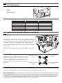
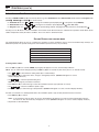
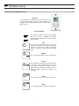
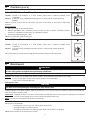
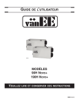
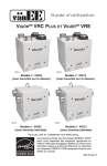
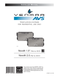
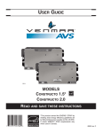
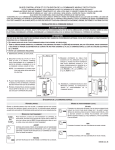
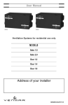
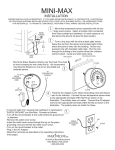
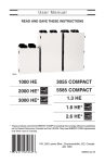
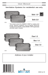
USER GUIDE
VB0157
MODELS
NOVOFIT 1.5*
NOVOFIT 2.0
READ
AND SAVE THESE INSTRUCTIONS
*This product earned the ENERGY STAR® by
meeting strict energy efficiency guidelines set by
Natural Resources Canada and the US EPA. It
meets ENERGY STAR requirements only
when used in Canada.
07998 rev. 05
About this Guide
This guide uses the following symbols to emphasize particular information:
! WARNING
Identifies an instruction which, if not followed, might cause serious personal injuries including possibility of
death.
CAUTION
Denotes an instruction which, if not followed, may severely damage the unit and/or its components.
NOTE: Indicates supplementary information needed to fully complete an instruction.
TABLE OF CONTENTS
1.
UNIT DESCRIPTION . . . . . . . . . . . . . . . . . . . . . . . . . . . . . . . . . . . . . . . . . . . . . . . . . . . . . . . . . . . . . . .3
1.1 SPECIFICATIONS . . . . . . . . . . . . . . . . . . . . . . . . . . . . . . . . . . . . . . . . . . . . . . . . . . . . . . . . . . . . . . . . . . . . . . . . . . . . . . . . .3
2.
FUNCTION OF THE HEAT RECOVERY VENTILATOR . . . . . . . . . . . . . . . . . . . . . . . . . . . . . . . . . . . .3
2.1 HEAT RECOVERY . . . . . . . . . . . . . . . . . . . . . . . . . . . . . . . . . . . . . . . . . . . . . . . . . . . . . . . . . . . . . . . . . . . . . . . . . . . . . . . . .3
2.2 RECIRCULATION . . . . . . . . . . . . . . . . . . . . . . . . . . . . . . . . . . . . . . . . . . . . . . . . . . . . . . . . . . . . . . . . . . . . . . . . . . . . . . . . .3
2.2 DEFROSTING . . . . . . . . . . . . . . . . . . . . . . . . . . . . . . . . . . . . . . . . . . . . . . . . . . . . . . . . . . . . . . . . . . . . . . . . . . . . . . . . . . . .3
3.
CONTROLS . . . . . . . . . . . . . . . . . . . . . . . . . . . . . . . . . . . . . . . . . . . . . . . . . . . . . . . . . . . . . . . . . . . .4-9
3.1
3.2
3.3
3.4
4.
ALTITUDE MAIN CONTROL . . . . . . . . . . . . . . . . . . . . . . . . . . . . . . . . . . . . . . . . . . . . . . . . . . . . . . . . . . . . . . . . . . . . . . . .4-6
DECO-TOUCH MAIN CONTROL . . . . . . . . . . . . . . . . . . . . . . . . . . . . . . . . . . . . . . . . . . . . . . . . . . . . . . . . . . . . . . . . . . . . .7-8
20/40/60-MINUTE PUSH-BUTTON TIMER (AUXILIARY CONTROL) . . . . . . . . . . . . . . . . . . . . . . . . . . . . . . . . . . . . . . . . . . . . . . . . .9
60-MINUTE MECHANICAL TIMER (AUXILIARY CONTROL) . . . . . . . . . . . . . . . . . . . . . . . . . . . . . . . . . . . . . . . . . . . . . . . . . . . . . . .9
MAINTENANCE . . . . . . . . . . . . . . . . . . . . . . . . . . . . . . . . . . . . . . . . . . . . . . . . . . . . . . . . . . . . . . . . . . .9
4.1 REGULAR . . . . . . . . . . . . . . . . . . . . . . . . . . . . . . . . . . . . . . . . . . . . . . . . . . . . . . . . . . . . . . . . . . . . . . . . . . . . . . . . . . . . . .9
4.2 PROLONGED . . . . . . . . . . . . . . . . . . . . . . . . . . . . . . . . . . . . . . . . . . . . . . . . . . . . . . . . . . . . . . . . . . . . . . . . . . . . . . . . . . . .9
5.
TROUBLESHOOTING . . . . . . . . . . . . . . . . . . . . . . . . . . . . . . . . . . . . . . . . . . . . . . . . . . . . . . . . . . . . .10
CONGRATULATIONS! You have made an excellent choice!
We have prepared this User Manual especially for you. Please read it carefully to ensure you obtain full benefits from your Heat
Recovery Ventilator unit.
CAUTION
1.
Some activities create dust or vapors which may damage your unit. You must therefore turn off and unplug
your unit in the following situations:
• major renovation work
• housing construction
• sanding (e.g. gypsum joints, etc.)
• varnishing
2.
During very heavy snowstorms, the unit should also be turned off or set on recirculation mode to avoid
problems caused by snow entering the unit, even if it is equipped with an anti-gust intake hood.
3.
At least once in a year, the unit mechanical and electronic parts should be inspected by qualified service
personnel.
2
1.
UNIT DESCRIPTION
1
1. Filters
2. Blowers
3. Condensation tray
4. Heat recovery core
4
2
1
1
3
VB0097
1.1
SPECIFICATIONS
MODEL
2.
FUNCTION
NOVOFIT 1.5
NOVOFIT 2.0
WIDTH
30¼’’ (768
MM)
30¼’’ (768
MM)
HEIGHT
16½’’ (419
MM)
16½’’ (419
MM)
DEPTH
17¹⁄8’’ (435
MM)
17¹⁄8’’ (435
MM)
WEIGHT
65
KG)
67
KG)
LB
(29.5
LB
(30.5
ELECTRICAL SUPPLY
120 V, 60 HZ
120 V, 60 HZ
POWER CONSUMPTION
150 W
240 W
OF THE
HEAT RECOVERY VENTILATOR
Your ventilation system will help eliminate poor air quality problems by
drawing the stale and humid air out of the house and replacing it with fresh
outside air. By eliminating accumulated pollutants and humidity, it maintains
an optimum air quality and an ideal relative humidity during cold season.
The unit is also equipped with a heat recovery core which reduces ventilation
costs in winter.
Shown with a forced air heating system; can also operate on its own.
VH0063
2.1
HEAT RECOVERY
Units equipped with a heat recovery core can reduce
ventilation costs in winter. The unit draws the heat from the
stale air and humid air before it is released and uses it to
heat the air coming in from outside. The recovery core is
designed in such a way that the stale air is never mixed with
the fresh air.
Example: (in winter)
Fresh air to building
16°C/61°F
Exhaust air to outside
6°C/43°F
Exhaust air from building
22°C/72°F
Fresh air from outside
0°C/32°F
VF0026
2.2
RECIRCULATION
In recirculation mode, the unit ceases to exchange air with the exterior. Continuous recirculation and a mechanical filter ensure the
purification of the ambient air inside the house. The mechanical filter traps dust particle visible to the eye.
2.3
DEFROSTING
When the outside temperature is below -5°C (23°F), heat recovery creates frost in the core. To maintain its proper operation, the unit is
programmed to defrost the recovery core. The defrosting frequency varies according to outside temperature. Defrosting lasts 6 minutes
(or 10 minutes if set on EXTENDED DEFROST). During the defrost cycle, the unit shifts to maximum speed and the dampers close.
After defrosting, the unit returns to the operating mode previously selected by the user.
3
3.
CONTROLS
3.1 ALTITUDE MAIN CONTROL
1
SMART Mode. Entirely automatic mode optimizing the ventilation.
2
Temperature Indicators.
3
Program Mode. Allows to program the desired ventilation
according to the period of the day.
8
10
9
11
4
Recirculation Mode. Manual mode performing air recirculation
inside the house.
5
Ventilation Mode. Manual mode performing air exchange with
the outside.
6
Animated Arrows showing ventilation status (recirculation or air
exchange).
7
Periods of the day (morning, day, evening and night).
12
7
13
6
1
VC0099
8
Week days.
9
Week-end days.
10
Hour display.
11
AM or PM display.
12
Appears only when setting backlight preferences.
13
Ventilation / Recirculation speeds and programming options.
5
CASING INDICATORS
AND
4
3
2
KEYS
A SMART key:
Enables and disables the SMART mode.
B Set key:
• Press 3 seconds to access setting periods for
Program mode.
G
F
• Confirms the chosen option and goes to following
setting.
C Arrow keys:
• Adjust ventilation and recirculation speeds.
• Allows to review the program’s period.
• Adjust Preference and Program values.
D Mode / Pref key:
• Mode: Selects whether Ventilation,
Recirculation or Program mode.
• Pref:
E Reset filter keys:
F Power indicator:
Push 3 seconds to access Preference
settings.
Press on B and D keys simultaneously for
5 seconds to turn off (reset) the filter maintenance
indicator.
Illuminates when the control is operating.
G Filter maintenance indicator: Perform filters maintenance.
(Refer to Section 4 Maintenance).
4
E
MODE
PREF
SET
SMART
B
A
VC0100
D
C
3.
CONTROLS (CONT’D)
3.1 ALTITUDE MAIN CONTROL (CONT’D)
The Altitude main control is pre-programmed and ready to go. All you have to do is to set day and time. Then check the settings below
and change if needed.
SETTING PREFERENCES
Press on MODE / PREF key (D) for 3 seconds.
NOTE: You can exit Preferences setting by pressing on MODE / PREF key (D) for 3 seconds any time in the process, or wait
60 seconds. The modified values will be kept in memory.
WHAT WILL YOU SEE
If the control will be set for the very first time, the current day will be the first setting to be made; MON (for Monday) will flash on screen.
If the control was previously set up, when setting preferences, the control returns to the last preference chosen on previous setting. While
setting Preferences, the corresponding setting value flashes (e.g.: while setting current hour, hour is flashing).
HOW TO PROCEED
For every settings in table below:
• Use
to select value.
• Press SET key (B) to confirm the selected preference and go to next setting.
SETTING
AVAILABLE VALUE
CURRENT DAY
HOUR
MON/TUE/WED/THU/FRI/SAT/SUN
12:00
DISPLAY
CURRENT
HOUR
CURRENT
MINUTE
TEMPERATURE
FROM
AM
PM
ON
DISPLAY
24
°C
OFF
OR
TO
ON
0°C
-25°C
32°F
-13°F
OR
FOR AIR EXCHANGE*
-40°F
1°C
OUTSIDE
TEMPERATURE
TO
TO
OR
40°C
27°C
OR
FOR AIR EXCHANGE*
*IN PROG
33°F
OR
SMART
TO
AM
PM
12
°F
OR
TEMPERATURE
MAXIMUM
OR
MON
12:00
00
-40°C
OUTSIDE
24:00
00 TO 59
°C
UNIT
OR
0 TO 12
FROM
INSIDE TEMPERATURE
MINIMUM
DEFAULT OPTIONS
OR
104°F
81°F
MODE, THESE LIMIT VALUES ALLOW TO STOP
AIR EXCHANGE WITH THE OUTSIDE
BACKLIGHT COLOR
BACKLIGHT DISPLAY
AUTO: BACKLIGHT
OFF MODE FOR
INTERMITTENT MODE
AFTER
BLUE OR GREEN
AUTO OR ON
10 SECONDS WHEN ANY
ON: BACKLIGHT ALWAYS ON.
VENTILATION/RECIRCULATION
OR VENTILATION/OFF
ACTIVATED
BLUE
AUTO
KEY IS PRESSED.
VENT/RECIRC.
A VENTILATION PERIOD, DETERMINES THE SECOND PART OF THE CYCLE
(RECIRCULATION
5
OR
OFF).
3.
CONTROLS (CONT’D)
3.1
ALTITUDE MAIN CONTROL (CONT’D)
Pressing on MODE / PREF key (D) successively allows to go from Ventilation mode to Recirculation mode and then to Program mode
(VENT 5 , RECIRC 4 and PROG 3 on control screen).
• In Ventilation Mode, use
• In Recirculation mode, use
• In Program mode, use
to change the ventilation speed (displayed in 13 in all options except RECIRC).
to change the recirculation speed (displayed in 13 , OFF, MIN, MAX).
to review the period settings without changing them (the period icons are displayed in 7 ).
Pressing once on A allows to turn the ventilation unit in Smart mode. On this mode, the ventilation unit operation will be driven by the
outdoor temperature and by the indoor conditions. Press once more to exit Smart mode.
SETTING PERIODS
FOR PROGRAM MODE
The Program Mode allows the user to customize the operation of his/her ventilation unit, for week and weekend days. All days are
divided in 4 periods. The periods starting hour and ventilation speed are factory set (see below).
DAILY
PERIOD
PERIOD 1
PERIOD 2
PERIOD 3
PERIOD 4
PERIODS DEFAULT SETTINGS
STARTING
(MORNING)
(DAY)
(EVENING)
(NIGHT)
HOUR
6:00 AM
9:00 AM
5:00 PM
11:00 PM
MODE
MIN
20 MIN/H
MIN
20 MIN/H
To change these values:
Press on SET key (B) for 3 seconds, PROG (for program) will appear on screen, and week days will flash.
NOTE: You can exit Periods setting by pressing on SET key (B) for 3 seconds any time in the process, or wait 60 seconds.
• Use
to select between setting week days or weekend days.
• Press SET key (B) to confirm the choice, and go to setting daily Period 1. (Period 1 will appear on screen,
and hour display will flash.)
• Use
to select the period starting hour.
NOTE: Time changes by 15 minutes increments.
• Press SET key (B) to confirm and go to select the ventilation speed or type (will flash on screen).
• Use
to select the ventilation speed or type.
• Press SET key (B) to confirm and go to daily Period 2. (Period 2 will appear on screen, and hour display will flash.)
Proceed as for Period 1 for all daily periods. Once the ventilation speed or type for daily Period 4 has been selected:
• Press SET key (B) to confirm.
NOTE : If the week days were the first to be set, the weekend days will appear on screen; but if the weekend days were the
first to be set, then the week days will appear on screen. (Period 1 will appear on screen, and hour display will flash.)
• Set periods as described above.
6
3.
CONTROLS (CONT’D)
3.2 DECO-TOUCH MAIN CONTROL
BACKLIGHT
If the backlight is not illuminated, the first button pressed
(no matter which button) shall turn on the backlight. The
backlight remains illuminated for 10 seconds after the last
button pressed.
OPERATING MODES
OR
VC0117
To change the operation mode of the ventilation
unit, press the UP or DOWN arrow button.
Operating mode label will then scroll up or down
on LCD screen.
OFF
Put the unit on stand-by mode, so it will only
respond to auxiliairy controls (if present). On LCD
screen, only the House is visible showing the
control is powered on. This is the factory default
mode.
RECIRC
Air is recirculated inside the house at high speed.
20 MIN/H
The ventilation unit exchanges air intermittently on
a one hour cycle as follows: OFF for 40 min. (or
recirculation on high speed for 40 min., see next
page) and then exchange air during 20 min. on
low speed. Repeat cycle after the 20 min. of air
exchange.
MIN
Air is exchanged with the outside on low speed.
MAX
Air is exchanged with the outside on high speed.
7
3.
CONTROLS (CONT’D)
3.2 DECO-TOUCH MAIN CONTROL (CONT’D)
HOW TO
SET THE RELATIVE HUMIDITY
BETWEEN
IN STANDBY OR
OFF
(RH) LEVEL AND CHOOSE
RECIRCULATION IN STAND-BY
DEHUMIDISTAT OVERRIDE SELECTION
In the operating modes MIN, MAX, 20 MIN/H and RECIRC, the user
can select a dehumidistat override so that if the relative humidity
(RH) in the house exceeds the RH setting previously stored, the
ventilation unit will exchange in high speed until the target indoor RH
setting is reached.
An air exchanger is not a dehumidifier, but it can change the
indoor relative humidity by bringing in drier or more humid air from
outside during non heating season. The dehumidistat override
function is useful to reduce indoor RH when the outdoor air is cool
and dry during the heating season. Select a target RH between
30% and 55% according to your comfort. When outdoor relative
humidity is high (e.g. in summer), turn off the override by pressing
OK until the RH display disappears.
When the dehumidistat override is activated, the
AUTO indicator will appear on LCD screen to show that
the actual mode is being overridden. Also, the relative
humidity appears (if it was not shown, see example
beside). Once the target humidity level is reached, the unit goes
back into its original operating mode and AUTO disappears from
LCD screen.
NOTE: If the actual mode is MAX, only the relative humidity level
appears on screen; AUTO label will not appear.
To engage the dehumidistat override, press OK. The actual indoor
RH and the %HUM label appear on LCD screen.
NOTE: If the actual RH is less than 20%, then the humidity indicator
will display “LO”, and if the actual RH is greater than
80%, then the humidity ndicator will display “HI”.
To turn off the dehumidistat override, press OK again. The RH and
%HUM display will disappear from LCD screen.
Setting the relative humidity level allows to select the maximum
desired indoor humidity level (in percentage). This value will be
used to start the dehumidistat override (air exchange in high
speed).
Press and hold OK for 3 sec. to access
the settings menu. The backlight will
be activated during all the procedure.
The Relative humidity arrow and value
will flash (default setting: 45%).
Use UP or DOWN
arrow to change the
value. The value changes
by 1% increments.
Lower value: 30%.
Upper value: 55%. Still
flashing.
OR
Press OK button to accept the new
value and go to next settting.
Two lines are flashing to show that
OFF¹ is in stand by (default configuration
setting).
MAINTENANCE INDICATOR
Press OK button to
accept and quit setting
menu.
The maintenance indicator is
represented by an M in a rounded
triangle, at the top of the house (see
beside). If this indicator is flashing,
perform the regularl maintenance,
and if it is not flashing, perform the
annual maintenance (refer to Section 4).
Recirculation arrows are turning and
rE
flashes
to
show
that
RECIRCULATION² is in standby.
1OFF
Resetting Maintenance Indicator: Press simultaneously
on both arrow buttons, Maintenance indicator will
disappear from LCD screen.
Press OK button to accept and quit
setting menu.
IN STAND BY: On
OR
OR
Use UP or DOWN
arrow to change to
RECIRCULATION
in standby.
AND
POWER FAILURE
20 min/h mode, the ventilation unit is OFF
during 40 minutes and exchange air with the
outside on low speed during the remaining
20 minutes of the hour. This is the default value.
2RECIRCULATION IN STAND BY:On 20 min/h mode, the ventilation
unit recirculates the inside air for
40 minutes on high speed and
exchange air with the outside on
low speed during the remaining
20 minutes of the hour.
After a power failure, the wall control returns to its original
operation mode. All settings are kept in memory.
8
3.
CONTROLS (CONT’D)
3.3
20/40/60-MINUTE PUSH-BUTTON TIMER (AUXILIARY CONTROL)
Location: Located in the bathroom or in other locations where there is temporary humidity excess
or pollutants.
Purpose: To eliminate excess humidity produced by showers or other periodic activities producing
pollutants.
Within 2 seconds, push one time for 20 minutes, two times for 40 minutes or three times for 60 minutes
activation.
Results expected:
1. Motor speed: high for 20, 40 or 60 minutes.
2. Indicator light GOES « ON » and flashes every 5 seconds (one time to indicate a 20-minute operation,
two times for a 40-minute and three times for a 60-minute operation.
3. Air exchange indicator light goes « ON »
NOTE: To stop activation, push one more time.
3.4
20 min.
40 min.
60 min.
VC0007
60-MINUTE MECHANICAL TIMER (AUXILIARY CONTROL)
Location: Located in the bathroom or in other locations where there is temporary humidity excess
or pollutants.
Purpose: To eliminate excess humidity produced by showers or other periodic activities producing
pollutants.
OFF
Turn
Past
HOLD
10
60
20
50
40
30
MINUTES
This control makes the system operate at high speed for periods varying from 10 to 60 minutes.
VC0017
4.
MAINTENANCE
! WARNING
In order to prevent personal injury, turn off the unit and uplug it before performing maintenance. It is recommended
to wear safety glasses and gloves when performing maintenance.
4.1
REGULAR
Air filters: The air filters are washable. Under normal conditions, we recommend to wash them every 3 months.
• Use a vacuum cleaner to remove the heaviest portion of accumulated dust.
• Then, wash in water and mild soap.
Heat Recovery Core:
CAUTION
Hot water and a strong detergent will damage the heat recovery core.
The heat recovery core must be handled with care. We recommend to wash it once a year, at the end of summer, in order to ensure
maximum efficiency of the plastic partitions. Allow the heat recovery core to soak for 3 hours in a solution of warm water and mild soap.
Rinse under a heavy stream of water.
Intake hood: Regularly check the screen in the exterior intake hood and clean when necessary. Also check during very cold weather
because ice may build up on the screen located in the exterior intake hood.
Motor: The motor is factory lubricated for life. Do not oil bushings.
4.2
PROLONGED
Annual service should include:
• Cleaning filters, heat recovery core and the exterior intake hood.
• Cleaning the blades of the blower wheels.
• Cleaning the condensation tray with soapy water (make sure the drain is not clogged).
NOTE: Ask your installer for an annual service contract.
9
5.
TROUBLESHOOTING
If the unit does not work properly, reset the unit by unplugging it for one minute and then replug it. If it still not working properly,
refer to table below.
TYPE OF PROBLEM
1.
TRY THIS...
On Altitude wall control, there is no •
outside temperature displayed on
screen
.
•
At its very start-up or after a power failure, it takes some minutes before the outside
temperature appears on screen. Set the wall control on MIN or MAX in VENT Mode.
2.
On Altitude or Deco-Touch wall
control, error code E1 or E3
appears on screen.
•
Contact your installer.
3.
Nothing works.
•
See if the unit is plugged in.
•
See if the unit is receiving power from the house circuit breaker or fuse.
•
Operate the unit at maximum speed (MAX.) during activities generating excess
humidity (family gatherings, extra cooking, etc.).
•
Leave curtains half-open to allow air circulation.
•
Store all firewood in a close room with a dehumidifier or in a well ventilated room,
or store the wood outside.
•
Keep the temperature in your house above 18°C (64°F).
•
Operate the unit at low speed (MIN.).
•
Temporarily switch to the intermittent mode.
•
Temporarily use a humidifier.
•
Make sure the outside hoods are not blocked.
•
Operate the unit at low speed (MIN.).
•
Have the system’s balancing checked.
•
Have the unit’s defrost system checked.
•
Install a duct heater.
4.
5.
6.
Condensation on windows.
(Air too humid.)
Air too dry.
Air too cold at the air supply grille.
If the problem is not solved by the above, contact your installer.
If the problem continues, contact your installer at the phone number and address listed below or call the following number for authorized
service center nearest you:
•
1-800-567-3855
YOUR INSTALLER’S ADDRESS
REPLACEMENT PARTS
AND
REPAIR
In order to ensure your ventilation unit remains in good working condition, you must use Venmar Ventilation Inc. genuine replacement
parts only. The Venmar Ventilation Inc. genuine replacement parts are specially designed for each unit and are manufactured to comply
with all the applicable certification standards and maintain a high standard of safety. Any third party replacement part used may cause
serious damage and drastically reduce the performance level of your unit, which will result in premature failing. Also, Venmar Ventilation Inc.
recommends to contact a certified service depot for all replacement parts and repairs.
10