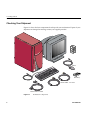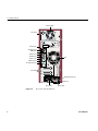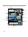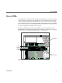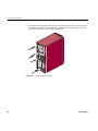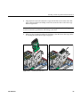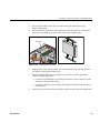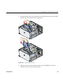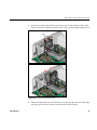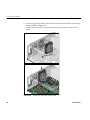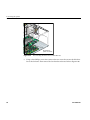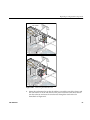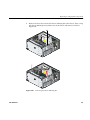
1
Silicon Graphics® Fuel™ Visual Workstation
Hardware User’s Guide
Document Number 007-4480-001
CONTRIBUTORS
Written by Matt Hoy and Mark Schwenden
Production by Karen Jacobson
Illustrated by Dan Young
Engineering contributions by Bob Sanders, Jim Pagura, Charles Alexander,
Francis L’Esperance, Brad Juskiewicz, Brad Daeda, Bruce Shifrin, Jesse Barker,
Jim Miller, Michael Wright, Wolfgang Szoecs, and many others.
Cover design by Sarah Bolles, Sarah Bolles Design, and Dany Galgani, SGI Technical Publications
COPYRIGHT
© 2002, Silicon Graphics, Inc.— All rights reserved; provided portions may be copyright in third parties, as indicated elsewhere herein. No
permission is granted to copy, distribute, or create derivative works from the contents of this electronic documentation is any manner, in whole
or in part, without the prior written permission of Silicon Graphics, Inc.
LIMITED RIGHTS LEGEND
The electronic (software) version of this document was developed at private expense; if acquired under an agreement with the USA government
or any contractor thereto, it is acquired as "commercial computer software" subject to the provisions of its applicable license agreement, as
specified in (a) 48 CFR 12.212 of the FAR; or, if acquired for Department of Defense units, (b) 48 CFR 227-7202 of the DoD FAR Supplement;
or sections succeeding thereto. Contractor/manufacturer is Silicon Graphics, Inc., 1600 Amphitheatre Pkwy 2E, Mountain View, CA
94043-1351, USA.
TRADEMARKS AND ATTRIBUTIONS
Silicon Graphics, SGI, the SGI logo, IRIS, and IRIX are registered trademarks, and IRIS InSight, Silicon Graphics Fuel, Stereo View, and VPro are
trademarks of Silicon Graphics, Inc.
Spaceball is a trademark of the Logitech group.
For regulatory and compliance information, see Appendix B, “Safety and Regulatory Information.”
Record of Revision
Version
Description
001
February 2002
Initial Publication
007-4480-001
iii
Contents
List of Figures .
.
.
.
.
.
.
.
.
.
.
.
.
.
.
.
.
.
.
.
.
.
.
. xi
List of Tables .
.
.
.
.
.
.
.
.
.
.
.
.
.
.
.
.
.
.
.
.
.
.
. xv
Conventions . . . . . . . . . . .
Software and System Administration Information
Product Support . . . . . . . . . .
Reader Comments . . . . . . . . . .
.
.
.
.
.
.
.
.
.
.
.
.
.
.
.
.
.
.
.
.
.
.
.
.
.
.
.
.
.
.
.
.
.
.
.
.
.
.
.
.
.
.
.
.
.
.
.
.
xviii
xviii
. xix
. xix
1.
Getting Started . . .
Checking Your Shipment .
Lifting the Workstation .
Getting Acquainted . .
Setting Up the Workstation
2.
Using the Workstation . . . . .
Logging In to the Workstation . . .
Using the IRIX Interactive Desktop . .
System Manager . . . . . .
Online Documentation . . . .
InfoSearch . . . . . . . .
The Console Window . . . .
Powering Off the Workstation . . .
Powering Off with the Power Button
Powering Off from the Toolchest .
Restarting from the Toolchest . . .
3.
System Components
System Enclosure .
System Board . .
Processor . . .
007-4480-001
.
.
.
.
.
.
.
.
.
.
.
.
.
.
.
.
.
.
.
.
.
.
.
.
.
.
.
.
.
.
.
.
.
.
.
.
.
.
.
.
.
.
.
.
.
.
.
.
.
.
.
.
.
.
.
.
.
.
.
.
.
.
.
.
.
.
.
.
.
.
.
.
.
.
.
.
.
.
.
.
.
.
.
.
.
.
.
.
.
.
.
.
.
.
.
.
.
.
.
.
.
.
.
.
.
.
.
.
.
.
.
.
.
.
.
.
.
.
.
.
.
.
.
.
1
2
3
4
7
.
.
.
.
.
.
.
.
.
.
.
.
.
.
.
.
.
.
.
.
.
.
.
.
.
.
.
.
.
.
.
.
.
.
.
.
.
.
.
.
.
.
.
.
.
.
.
.
.
.
.
.
.
.
.
.
.
.
.
.
.
.
.
.
.
.
.
.
.
.
.
.
.
.
.
.
.
.
.
.
.
.
.
.
.
.
.
.
.
.
.
.
.
.
.
.
.
.
.
.
.
.
.
.
.
.
.
.
.
.
.
.
.
.
.
.
.
.
.
.
.
.
.
.
.
.
.
.
.
.
.
.
.
.
.
.
.
.
.
.
.
.
.
.
.
.
.
.
.
.
.
.
.
.
.
.
.
.
.
.
.
.
.
.
.
.
.
.
.
.
.
.
.
.
.
.
13
14
16
17
17
17
18
18
18
21
23
.
.
.
.
.
.
.
.
.
.
.
.
.
.
.
.
.
.
.
.
.
.
.
.
.
.
.
.
.
.
.
.
.
.
.
.
.
.
.
.
.
.
.
.
.
.
.
.
.
.
.
.
.
.
.
.
.
.
.
.
.
.
.
.
25
26
28
30
v
Contents
4.
vi
Memory DIMMs . . . . . . . . . .
Internal Hard Disk Drives . . . . . . . .
Removable Media Drives . . . . . . . .
Graphics Module . . . . . . . . . .
PCI Boards . . . . . . . . . . . .
Power Supply . . . . . . . . . . .
Cooling System . . . . . . . . . . .
Optional Components, Peripherals, and Upgrades.
PCI Boards . . . . . . . . . . .
Memory Upgrades. . . . . . . . .
Graphics Boards . . . . . . . . .
Processor Upgrades . . . . . . . .
Storage Upgrades . . . . . . . . .
Displays. . . . . . . . . . . .
Peripherals . . . . . . . . . . .
.
.
.
.
.
.
.
.
.
.
.
.
.
.
.
.
.
.
.
.
.
.
.
.
.
.
.
.
.
.
.
.
.
.
.
.
.
.
.
.
.
.
.
.
.
.
.
.
.
.
.
.
.
.
.
.
.
.
.
.
.
.
.
.
.
.
.
.
.
.
.
.
.
.
.
.
.
.
.
.
.
.
.
.
.
.
.
.
.
.
.
.
.
.
.
.
.
.
.
.
.
.
.
.
.
.
.
.
.
.
.
.
.
.
.
.
.
.
.
.
.
.
.
.
.
.
.
.
.
.
.
.
.
.
.
.
.
.
.
.
.
.
.
.
.
.
.
.
.
.
.
.
.
.
.
.
.
.
.
.
.
.
.
.
.
.
.
.
.
.
.
.
.
.
.
.
.
.
.
.
. 31
. 32
. 34
. 35
. 38
. 39
. 40
. 42
. 42
. 42
. 42
. 43
. 43
. 43
. 44
Servicing the System . . . . . .
Ordering Parts . . . . . . . .
Service Procedures and Precautions . .
Preparing the Workstation for Service
Removing the Side Panel . . . .
Installing or Removing Internal Parts
Returning the Workstation to Service
Installing or Removing a Memory DIMM
Removing a DIMM . . . . .
Installing a DIMM . . . . . .
Verifying Memory Installation . .
.
.
.
.
.
.
.
.
.
.
.
.
.
.
.
.
.
.
.
.
.
.
.
.
.
.
.
.
.
.
.
.
.
.
.
.
.
.
.
.
.
.
.
.
.
.
.
.
.
.
.
.
.
.
.
.
.
.
.
.
.
.
.
.
.
.
.
.
.
.
.
.
.
.
.
.
.
.
.
.
.
.
.
.
.
.
.
.
.
.
.
.
.
.
.
.
.
.
.
.
.
.
.
.
.
.
.
.
.
.
.
.
.
.
.
.
.
.
.
.
.
.
.
.
.
.
.
.
.
.
.
.
. 45
. 45
. 46
. 46
. 49
. 52
. 55
. 58
. 59
. 61
. 62
.
.
.
.
.
.
.
.
.
.
.
.
.
.
.
.
.
.
.
.
.
.
.
.
.
.
.
.
.
.
.
.
.
007-4480-001
Contents
Installing or Removing Internal Hard Disk Drives . . . . . .
Installing or Removing a Drive in the Lower Hard Disk Drive Cage
Opening the Lower Drive Cage . . . . . . . . .
Installing a Disk Drive in the Lower Drive Cage . . . . .
Removing a Disk Drive from the Lower Drive Cage. . . .
Closing the Lower Drive Cage . . . . . . . . . .
Installing or Removing a Drive in the Upper Hard Disk Drive Cage
Installing a Disk Drive in the Upper Drive Cage . . . . .
Removing a Disk Drive from the Upper Drive Cage. . . .
Installing or Removing a Removable Media Drives . . . . . .
Installing a Removable Media Drive . . . . . . . . .
Removing a Removable Media Drive . . . . . . . . .
Installing or Removing a PCI Board . . . . . . . . . . .
Accessing the PCI Boards . . . . . . . . . . . .
Installing a PCI Board . . . . . . . . . . . . .
Removing a PCI Board . . . . . . . . . . . . .
Completing the PCI Board Installation or Removal . . . . .
Installing or Removing External devices . . . . . . . . .
Installing Locking Devices . . . . . . . . . . . . .
Installing a Locking Loop and a Padlock . . . . . . . .
Installing a Kensington Lock . . . . . . . . . . .
Replacing Cooling System Components . . . . . . . . .
Replacing the Motherboard Air Duct . . . . . . . . .
Replacing the Exhaust Fan . . . . . . . . . . . .
Replacing the Hard Disk Drive Fan. . . . . . . . . .
Replacing the PCI and Graphics Fan Housing . . . . . .
Replacing Chassis Components . . . . . . . . . . . .
Replacing Chassis Feet . . . . . . . . . . . . .
Replacing the Bezel Assembly . . . . . . . . . . .
Removing the Bezel . . . . . . . . . . . . .
Installing the Bezel . . . . . . . . . . . . .
Replacing the Switch/LED Assembly . . . . . . . . .
007-4480-001
.
.
.
.
.
.
.
.
.
.
.
.
.
.
.
.
.
.
.
.
.
.
.
.
.
.
.
.
.
.
.
.
.
.
.
.
.
.
.
.
.
.
.
.
.
.
.
.
.
.
.
.
.
.
.
.
.
.
.
.
.
.
.
.
.
.
.
.
.
.
.
.
.
.
.
.
.
.
.
.
.
.
.
.
.
.
.
.
.
.
.
.
.
.
.
.
.
.
.
.
.
.
.
.
.
.
.
.
.
.
.
.
.
.
.
.
.
.
.
.
.
.
.
.
.
.
.
.
.
.
.
.
.
.
.
.
.
.
.
.
.
.
.
.
.
.
.
.
.
.
.
.
.
.
.
.
.
.
.
.
.
.
.
.
.
.
.
.
.
.
.
.
.
.
.
.
.
.
.
.
.
.
.
.
.
.
.
.
.
.
.
.
. 63
. 63
. 63
. 64
. 66
. 67
. 68
. 68
. 70
. 72
. 72
. 75
. 77
. 78
. 80
. 82
. 82
. 84
. 84
. 85
. 86
. 87
. 88
. 92
. 95
.100
.104
.104
.104
.104
.106
.107
vii
Contents
viii
5.
Troubleshooting and Diagnostics .
Troubleshooting . . . . . .
Environmental Fault Monitoring
LED Lightbar . . . . . .
Diagnostics . . . . . . . .
Power-on Diagnostics . . . .
Offline Diagnostics . . . .
Online Diagnostics . . . .
Example Output . . . .
.
.
.
.
.
.
.
.
.
.
.
.
.
.
.
.
.
.
A.
Technical Specifications . . . . . .
Physical Environment Specifications. . .
Power Supply Specifications . . . . .
I/O Port Specifications. . . . . . .
Ethernet 10-Base-T/100-Base-T Port. .
IEEE 1284-A Parallel Port . . . . .
Keyboard and Mouse Ports . . . .
Serial Ports . . . . . . . . .
USB Ports . . . . . . . . .
Serial Cables and Adapter Specifications .
Printer/Dumb Terminal Serial Cable .
PC Modem Serial Cable . . . . .
Serial Port Adapter Cables . . . .
VPro Graphics Board I/O Port Specifications
DVI-I Video Port . . . . . . .
Stereo View Port . . . . . . .
Genlock Port . . . . . . . .
Swap Ready Port . . . . . . .
.
.
.
.
.
.
.
.
.
.
.
.
.
.
.
.
.
.
.
.
.
.
.
.
.
.
.
.
.
.
.
.
.
.
.
.
.
.
.
.
.
.
.
.
.
.
.
.
.
.
.
.
.
.
.
.
.
.
.
.
.
.
.
.
.
.
.
.
.
.
.
.
.
.
.
.
.
.
.
.
.
.
.
.
.
.
.
.
.
.
.
.
.
.
.
.
.
.
.
.
.
.
.
.
.
.
.
.
.
.
.
.
.
.
.
.
.
.
.
.
.
.
.
.
.
.
109
110
110
110
111
111
112
115
117
.
.
.
.
.
.
.
.
.
.
.
.
.
.
.
.
.
.
.
.
.
.
.
.
.
.
.
.
.
.
.
.
.
.
.
.
.
.
.
.
.
.
.
.
.
.
.
.
.
.
.
.
.
.
.
.
.
.
.
.
.
.
.
.
.
.
.
.
.
.
.
.
.
.
.
.
.
.
.
.
.
.
.
.
.
.
.
.
.
.
.
.
.
.
.
.
.
.
.
.
.
.
.
.
.
.
.
.
.
.
.
.
.
.
.
.
.
.
.
.
.
.
.
.
.
.
.
.
.
.
.
.
.
.
.
.
.
.
.
.
.
.
.
.
.
.
.
.
.
.
.
.
.
.
.
.
.
.
.
.
.
.
.
.
.
.
.
.
.
.
.
.
.
.
.
.
.
.
.
.
.
.
.
.
.
.
.
.
.
.
.
.
.
.
.
.
.
.
.
.
.
.
.
.
.
.
.
.
.
.
.
.
.
.
.
.
.
.
.
.
.
.
.
.
.
.
.
.
.
.
.
.
.
.
.
.
.
.
.
.
.
.
.
.
.
.
.
.
.
.
.
.
119
120
122
123
124
125
127
128
130
131
132
133
134
136
136
139
140
141
007-4480-001
Contents
B.
Safety and Regulatory Information . . . . . . .
Regulatory Declarations . . . . . . . . . . .
CMN Number . . . . . . . . . . . . .
CE Notice and Manufacturer’s Declaration of Conformity
Electromagnetic Emissions . . . . . . . . .
FCC Notice (USA Only) . . . . . . . . .
Industry Canada Notice (Canada Only) . . . .
VCCI Notice (Japan Only) . . . . . . . .
Chinese Class A Regulatory Notice . . . . .
Korean Class A Regulatory Notice . . . . . .
Shielded Cables . . . . . . . . . . . .
Electrostatic Discharge . . . . . . . . . .
Laser Compliance Statements . . . . . . . .
Lithium Battery Statement . . . . . . . . .
Safety Instructions . . . . . . . . . . . . .
Human Factors Guidelines for Setting Up Your Workstation
ANSI Standard for VDT Workstations . . . . . .
CAD Operator Preferences . . . . . . . . .
.
.
.
.
.
.
.
.
.
.
.
.
.
.
.
.
.
.
.
.
.
.
.
.
.
.
.
.
.
.
.
.
.
.
.
.
.
.
.
.
.
.
.
.
.
.
.
.
.
.
.
.
.
.
.
.
.
.
.
.
.
.
.
.
.
.
.
.
.
.
.
.
.
.
.
.
.
.
.
.
.
.
.
.
.
.
.
.
.
.
.
.
.
.
.
.
.
.
.
.
.
.
.
.
.
.
.
.
.
.
.
.
.
.
.
.
.
.
.
.
.
.
.
.
.
.
.
.
.
.
.
.
.
.
.
.
.
.
.
.
.
.
.
.
.
.
.
.
.
.
.
.
.
.
.
.
.
.
.
.
.
.
.143
.143
.144
.144
.144
.144
.145
.146
.146
.146
.146
.147
.147
.147
.147
.149
.149
.151
C.
Internal Cabling Diagrams .
Internal Power Cabling . .
Internal SCSI Cabling . . .
Index
007-4480-001
.
.
.
.
.
.
.
.
.
.
.
.
.
.
.
.
.
.
.
.
.
.
.
.
.
.
.
.
.
.
.
.
.
.
.
.
.
.
.
.
.
.
.
.
.
.
.
.
.
.
.
.
.
.
.
.
.
.
.
.
.
.153
.154
.155
.
.
.
.
.
.
.
.
.
.
.
.
.
.
.
.
.
.
.157
ix
List of Figures
Figure 1-1
Figure 1-2
Figure 1-3
Figure 1-4
Figure 1-5
Figure 1-6
Figure 1-7
Figure 1-8
Figure 2-1
Figure 2-2
Figure 2-3
Figure 2-4
Figure 2-5
Figure 2-6
Figure 2-7
Figure 2-8
Figure 2-9
Figure 2-10
Figure 2-11
Figure 2-12
Figure 2-13
Figure 2-14
Figure 2-15
Figure 3-1
Figure 3-2
Figure 3-3
Figure 3-4
007-4480-001
Workstation Components .
Lifting the Workstation .
.
.
.
.
.
.
.
.
.
.
.
.
.
.
.
.
Front View of the Workstation . . . . . . .
Rear View of the Workstation. . . . . . . .
Connecting the Keyboard and Mouse Cables . . .
Connecting the Ethernet Cable . . . . . . .
Connecting the Monitor Cable . . . . . . .
Connecting the Workstation and Monitor Power Cables
Powering On the Workstation and Monitor. . . .
Login Screen . . . . . . . . . . . .
Peripheral Icons. . . . . . . . . . . .
Toolchest Menu. . . . . . . . . . . .
Console Window . . . . . . . . . . .
Powering Off the Workstation . . . . . . .
System Shutdown Notifier . . . . . . . .
Power Button and Reset Button . . . . . . .
Shutdown Caution Message . . . . . . . .
Restart System Option . . . . . . . . . .
System Shutdown Notifier . . . . . . . .
Restart Notifier . . . . . . . . . . . .
System Shutdown Notifier . . . . . . . .
Power Off/Restart Notifier . . . . . . . .
Restart Notifier . . . . . . . . . . . .
System Enclosure Layout . . . . . . . . .
System Board . . . . . . . . . . . .
Processor Integrated Multi-module Board . . . .
DIMM Sockets and Pairs . . . . . . . . .
.
.
.
.
.
.
.
.
2
3
.
.
.
.
.
.
.
.
.
.
.
.
.
.
.
.
.
.
.
.
.
.
.
.
.
.
.
.
.
.
.
.
.
.
.
.
.
.
.
.
.
.
.
.
.
.
.
.
.
.
.
.
.
.
.
.
.
.
.
.
.
.
.
.
.
.
.
.
.
.
.
.
.
.
.
.
.
.
.
.
.
.
.
.
.
.
.
.
.
.
.
.
.
.
.
.
.
.
.
.
5
6
7
8
10
11
14
15
16
16
18
19
19
20
21
22
22
23
24
24
24
27
29
30
31
xi
List of Figures
Figure 3-5
Figure 3-6
Figure 3-7
Figure 3-8
Figure 3-9
Figure 3-10
Figure 3-11
Figure 4-1
Figure 4-2
Figure 4-3
Figure 4-4
Figure 4-5
Figure 4-6
Figure 4-7
Figure 4-8
Figure 4-9
Figure 4-10
Figure 4-11
Figure 4-12
Figure 4-13
Figure 4-14
Figure 4-15
Figure 4-16
Figure 4-17
Figure 4-18
Figure 4-19
Figure 4-20
Figure 4-21
Figure 4-22
Figure 4-23
Figure 4-24
Figure 4-25
Figure 4-26
xii
Internal Hard Disk Drive Cages . . . . . .
Removable Media Drive Bay . . . . . . .
Locating the Graphics Module. . . . . . .
VPro Graphics and Dual Channel Display I/O Ports
PCI Busses and Slots . . . . . . . . .
Power Supply Location . . . . . . . . .
Cooling System Components . . . . . . .
Powering Off the System . . . . . . . .
Disconnecting the Cables . . . . . . . .
Removing the Padlock . . . . . . . . .
Removing the Side Panel . . . . . . . .
Laying Down the System Enclosure . . . . .
Attaching the Wrist Strap to the Chassis . . . .
Replacing the Side Panel . . . . . . . .
Connecting the System Cables . . . . . . .
Removing a DIMM . . . . . . . . . .
Installing a DIMM . . . . . . . . . .
Locating the Notches on a DIMM . . . . . .
Opening the Lower Drive Cage . . . . . .
Installing the Disk Drive . . . . . . . .
Removing the Disk Drive . . . . . . . .
Closing the Lower Drive Cage . . . . . . .
Installing the Drive Rails . . . . . . . .
Installing the Disk Drive . . . . . . . .
Removing the Disk Drive . . . . . . . .
Installing the Drive Cage Cover . . . . . .
Installing the Drive Rails . . . . . . . .
Installing the Removable Media Drive . . . .
Removing a Removable Media Drive . . . . .
Opening the Lower Drive Cage . . . . . .
Removing the Chassis Stiffening Bar . . . . .
Opening the PCI Gate . . . . . . . . .
Installing the PCI Board . . . . . . . .
.
.
.
.
.
.
.
.
.
.
.
.
.
.
.
.
.
.
.
.
.
.
.
.
.
.
.
.
.
.
.
.
.
.
.
.
.
.
.
.
.
.
.
.
.
.
.
.
.
.
.
.
.
.
.
.
.
.
.
.
.
.
.
.
.
.
.
.
.
.
.
.
.
.
.
.
.
.
.
.
.
.
.
.
.
.
.
.
.
.
.
.
.
.
.
.
.
.
.
.
.
.
.
.
.
.
.
.
.
.
.
.
.
.
.
.
.
.
.
.
.
.
.
.
.
.
.
.
.
.
.
.
. 33
. 34
. 36
. 37
. 38
. 39
. 41
. 47
. 48
. 49
. 50
. 51
. 53
. 56
. 57
. 59
. 61
. 62
. 64
. 65
. 66
. 67
. 68
. 69
. 70
. 71
. 73
. 74
. 76
. 78
. 79
. 80
. 81
007-4480-001
List of Figures
Figure 4-27
Figure 4-28
Figure 4-29
Figure 4-30
Figure 4-31
Figure 4-32
Figure 4-33
Figure 4-34
Figure 4-35
Figure 4-36
Figure 4-37
Figure 4-38
Figure 4-39
Figure 4-40
Figure 4-41
Figure 4-42
Figure 4-43
Figure 4-44
Figure 4-45
Figure 4-46
Figure 4-47
Figure A-1
Figure A-2
Figure A-3
Figure A-4
Figure A-5
Figure A-6
Figure A-7
Figure A-8
Figure A-9
Figure B-1
Figure B-2
Figure B-3
007-4480-001
Closing the PCI Gate . . . . . . . . .
Installing the Chassis Stiffening Arm . . . .
Removing the Locking Loop from Storage . . .
Installing the Locking Loop . . . . . . .
Kensington Lock Slot . . . . . . . . .
Opening the Lower Drive Cage . . . . . .
Removing the Air Duct . . . . . . . .
Installing the Replacement Air Duct . . . . .
Closing the Lower Drive Cage . . . . . .
Disconnecting the Exhaust Fan Wire Harness . .
Removing the Exhaust Fan . . . . . . .
Installing the Replacement Exhaust Fan . . . .
Disconnecting the Disk Drive Fan Wire Harness .
Removing the Disk Drive Fan. . . . . . .
Installing the Replacement Disk Drive Fan . . .
Opening the Lower Drive Cage . . . . . .
Removing the Chassis Stiffening Bar. . . . .
Removing the PCI and Graphics Fan Housing . .
Removing the Bezel . . . . . . . . .
Install the Bezel . . . . . . . . . . .
Replacing the Switch/LED Wire Harness Assembly
Ethernet 10-Base-T/100-Base-T Port . . . . .
IEEE 1284-A Parallel Port . . . . . . . .
Keyboard and Mouse Ports . . . . . . .
Serial Port . . . . . . . . . . . .
USB-A Port . . . . . . . . . . . .
DVI-I Port . . . . . . . . . . . .
StereoView Port. . . . . . . . . . .
Genlock Port . . . . . . . . . . .
Swap Ready Port . . . . . . . . . .
VCCI Notice (Japan Only) . . . . . . . .
Chinese Class A Regulatory Notice . . . . .
Korean Class A Regulatory Notice . . . . .
.
.
.
.
.
.
.
.
.
.
.
.
.
.
.
.
.
.
.
.
.
.
.
.
.
.
.
.
.
.
.
.
.
.
.
.
.
.
.
.
.
.
.
.
.
.
.
.
.
.
.
.
.
.
.
.
.
.
.
.
.
.
.
.
.
.
.
.
.
.
.
.
.
.
.
.
.
.
.
.
.
.
.
.
.
.
.
.
.
.
.
.
.
.
.
.
.
.
.
.
.
.
.
.
.
.
.
.
.
.
.
.
.
.
.
.
.
.
.
.
.
.
.
.
.
.
.
.
.
.
.
.
. 82
. 83
. 85
. 86
. 87
. 88
. 89
. 90
. 91
. 92
. 93
. 94
. 96
. 97
. 99
.100
.101
.103
.105
.106
.107
.124
.125
.127
.128
.130
.136
.139
.140
.141
.146
.146
.146
xiii
List of Figures
Figure B-4
Figure C-1
Figure C-2
Figure C-3
xiv
Basic Parameters of Visual Display Terminal Workstation
Adjustment (Adapted From ANSI/HFS 100-1988) . . .
Internal Power Cabling . . . . . . . . . . .
Internal SCSI Cabling . . . . . . . . . . .
Internal SCSI Cable Pinouts . . . . . . . . .
.
.
.
.
.
.
.
.
150
154
155
156
007-4480-001
List of Tables
Table i
Table 4-1
Table 5-1
Table 5-2
Table 5-3
Table A-1
Table A-2
Table A-3
Table A-4
Table A-5
Table A-6
Table A-7
Table A-8
Table A-9
Table A-10
Table A-11
Table A-12
Table A-13
Table A-14
Table A-15
Table A-16
Table B-1
Table B-2
007-4480-001
Documentation Conventions . . . . . . . . . .
Customer-replaceable Components and Service Procedures .
.
.
xviii
. 54
LED Lightbar Signals . . . . . . . . . . . . .
Time Required to Run Offline Diagnostics . . . . . . .
runalldiags Command-line Options . . . . . . . . .
Physical Environment Specifications. . . . . . . . .
Power Supply Specifications . . . . . . . . . . .
Ethernet 10-Base-T/100-Base-T Port Pinout . . . . . . .
IEEE 1284-A Parallel Port Pinout . . . . . . . . . .
Keyboard and Mouse Port Pinout . . . . . . . . .
Serial Port Pinout . . . . . . . . . . . . . .
USB-A Port Pinout . . . . . . . . . . . . . .
Printer/Dumb Terminal Cable Pinout . . . . . . . .
PC Modem Cable Pinout . . . . . . . . . . . .
Female DB-9 to Female MiniDIN8 Adapter Cable Pinout . . .
Female DB-9 to Female DB-9 Adapter Cable Pinout . . . .
DVI-I Video Port Pinout . . . . . . . . . . . .
Supported VPro Graphics Board Scan Rates . . . . . .
Stereo View Pinout Assignments . . . . . . . . . .
Genlock Pinout Assignments . . . . . . . . . . .
Swap Ready Pinout Assignments . . . . . . . . .
ANSI/HFS 100-1988 Guidelines for VDT Workplace Adjustment
Workstation Adjustments Preferred by CAD Users . . . .
.110
.113
.116
.120
.122
.124
.126
.127
.129
.130
.132
.133
.134
.135
.137
.138
.139
.140
.141
.149
.151
xv
About This Guide
Welcome to the user’s guide for the Silicon Graphics Fuel visual workstation. Your new
workstation offers VPro graphics, a high-performance MIPS processor, and a
high-bandwidth architecture designed to maximize the performance of your desktop
applications.
Note: This User's Guide has been translated and is available to download from the SGI
Technical Publications Library at http://techpubs.sgi.com.
Enter the keywords Fuel + <language> to find the version you need.
This guide shows you how to set up, use, and troubleshoot your system. You’ll learn to:
•
Set up your workstation
•
Access online information
•
Install and remove internal parts
•
Install and remove peripherals
•
Diagnose hardware problems
This guide also provides:
007-4480-001
•
Technical specifications
•
Safety and regulatory information
xvii
About This Guide
This guide is provided for all end-users and SGI technical support staff. Most of the
hardware tasks are relatively simple and require no previous computer knowledge. A
few tasks are lengthy; they are easier to perform if you have some computer hardware
experience.
Conventions
Table i shows the conventions used in this document.
Table i
Documentation Conventions
Convention
Meaning
Toolchest > Help > Online Books
The “>” is used to indicate direction in an on-screen
menu hierarchy. In this example, “Online Books” is
listed under the “Help” menu, which is listed under the
“Toolchest” menu.
Silicon Graphics Fuel
Hardware User’s Guide
Document titles are shown in italics. This applies to
both online and print documents.
>>ls -al
User input is shown in boldface, fixed-width type.
Software and System Administration Information
For complete information on installing software, see the online Personal System
Administration Guide. It is located on your desktop in Toolchest > Help > Online Books. For
more advanced information, see the online IRIX Admin: Software Installation & Licensing
Guide. For system administration information, see the SGI_Admin section of the online
bookshelf.
It is always a good idea to back up your system. For instructions on backing up your
system, see the online Personal System Administration Guide.
xviii
007-4480-001
About This Guide
Product Support
The Silicon Graphics Fuel visual workstation is designed for user maintenance and
repair without the help of a trained technician. For product support information, contact
your SGI subsidiary or authorized distributor.
SGI provides a comprehensive range of product support for its products. If you are in
North America, contact the Technical Assistance Center at + 1 800 800 4SGI or your
authorized service provider. If you are outside North America, contact the SGI
subsidiary or authorized distributor in your country. For more information about
product support, refer to the following website:
http://www.sgi.com/support/index.html
Reader Comments
If you have comments about the technical accuracy, content, or organization of this
document, please contact SGI. Be sure to include the title and part number of the
document with your comments. The part number for this document is printed on the
front or back cover. You can contact SGI in any of the following ways:
•
Send e-mail to the following address: [email protected]
•
Send a fax to the attention of “Technical Publications” at +1 650 932 0801
•
Use the Suggestion Box form on the Technical Publications Library World Wide
Web page: http://techpubs.sgi.com
•
Call the Technical Publications Group through the Technical Assistance Center at
+1 800 800 4SGI.
•
Send mail to: Technical Publications, SGI, 1600 Amphitheatre Pkwy., M/S 535,
Mountain View, California, 94043-1351, USA.
SGI values your comments and will respond to them promptly.
007-4480-001
xix
Chapter 1
1. Getting Started
This chapter shows you how to set up your Silicon Graphics Fuel visual workstation. The
following topics are covered:
007-4480-001
•
“Checking Your Shipment” on page 2
•
“Lifting the Workstation” on page 3
•
“Getting Acquainted” on page 4
•
“Setting Up the Workstation” on page 7
1
1: Getting Started
Checking Your Shipment
Figure 1-1 shows the basic components that ship with your workstation. If parts of your
shipment are damaged or missing, contact your support provider.
CDs
Mouse
Wrist strap
Power cables - 10 ft. each
Monitor cable - 3 meters
Figure 1-1
2
Workstation Components
007-4480-001
Lifting the Workstation
Lifting the Workstation
The base workstation configuration weighs 42 lb. (19 kg). SGI highly recommends that
two people lift the unit when it must be moved. Lift the unit by placing your hands under
the bottom edges of the chassis, as shown in Figure 1-2.
This
device
Japan
comp
VCCI
lies
with
and
Europ FCC
ean Part 15,
CISPR
radio
Cana
freque
Class 22
da
DOC,
ncy
A
emiss
Silicon
NRTL/C
Graph
ions
LR96309
ics,
Inc.
VCC
1600
006770789
Class I
Mount Amphi
A
theatre
Copyri ain View,
Parkw
ght
CA
2001
94043 ay
Silicon
-1351
Graph
Mode All rights ics,
l No.: reservInc.
made CMN ed
ACN
1
2
015
in
024-X the USA
XXX-
001
2
1
Figure 1-2
007-4480-001
Lifting the Workstation
3
1: Getting Started
Getting Acquainted
To become familiar with your workstation, refer to the following figures:
•
Figure 1-3, which shows the front view of the workstation.
•
Figure 1-4, which shows the rear view of the workstation.
After you have set up your workstation and logged in, refer to the following resources
for more information:
4
•
From the Toolchest, select System > System Manager for information on the
workstation’s hardware and software.
•
From the Toolchest, select System > System Manager > About This System to
learn about your system’s serial number, IP address, operating system, and more.
007-4480-001
Getting Acquainted
Figure 1-3
007-4480-001
Front View of the Workstation
5
1: Getting Started
Power supply
AC power
This device complies with FCC Part 15, Canada DOC,
Japan VCCI and European radio frequency emissions
requirements. Refer to user manual for full information.
CISPR 22
Class A
VCCI
NRTL/C
LR96309
Class A
ACN 006770789
Silicon Graphics, Inc. 1600 Amphitheatre Parkway
Mountain View, CA 94043-1351
Copyright 2001 Silicon Graphics, Inc.
All rights reserved
Model No.: CMN 015
made in the USA
024-XXXX-001
Mouse port
Keyboard port
USB ports
Serial 2 port
2
Parallel port
Fan
1
Serial 1 port
Ethernet port
L1 diagnostic port
PCI slots
Kensington lock slot
R
L
Genlock
DVI-I video
Figure 1-4
6
Stereo View
Rear View of the Workstation
007-4480-001
Setting Up the Workstation
Setting Up the Workstation
To set up the workstation, follow these steps:
1.
Connect the keyboard and mouse cables, as shown in Figure 1-5.
Thi
s
Jap device
req an VC com
uire CI plie
me and s with
nts. Eur
Ref ope FCC
er to an rad Par
use io t 15,
r ma freq Can
CIS
PR
nua uency ada
l for em DO
Clas 22
sA
full issi C,
info ons
rma
Silic
NRTL
tion
/C
on
LR963
Gra
.
phic
s, Inc.
09
VC
ACN
Mou 1600
006770
Clas CI
ntai Amp
789
sA
n View hith
eatr
, CA e Park
yrig
940 way
ht 200
43-1
1 Silic
351
on
Gra
Mo All righ phics,
del
ts
Inc.
No.: reserved
Cop
CM
ma
de
in N 015
024 the US
-XX
XX A
-00
1
2
1
Figure 1-5
007-4480-001
Connecting the Keyboard and Mouse Cables
7
1: Getting Started
2. Connect the Ethernet cable to the Ethernet port, as shown in Figure 1-6.
Thi
s
Jap device
req an VC com
uire CI plie
me and s with
nts. Eur
Ref ope FCC
er to an rad Par
use io t 15,
r ma freq Can
CIS
PR
nua uency ada
l for em DO
Clas 22
sA
full issi C,
info ons
rma
Silic
NRTL/
tion
on
C
LR963
Gra
.
phic
s, Inc.
09
VC
ACN
Mou 1600
006770
Clas CI
ntai Amp
789
sA
n View hith
eatr
, CA e Park
yrig
940 way
ht 200
43-1
1 Silic
351
on
Gra
Mo All righ phics,
del
ts
Inc.
No.: reserved
Cop
CM
ma
de
in N 015
024 the US
-XX
XX A
-00
1
2
1
Figure 1-6
8
Connecting the Ethernet Cable
007-4480-001
Setting Up the Workstation
3. Connect the monitor cable, as follows (Figure 1-7):
•
Connect the monitor-to-graphics cable to the monitor.
•
Connect the monitor-to-graphics cable to the DVI-I video connector on the back
of your workstation.
Note: The Silicon Graphics Fuel visual workstation can be connected to a variety of
monitors. Your monitor and monitor cable may differ from those shown. If your
monitor has multiple inputs, ensure that the source switch is set to the correct input
port.
007-4480-001
9
1: Getting Started
Thi
s
Jap device
req an VC com
uire CI plie
me and s with
nts. Eur
Ref ope FCC
er to an rad Par
use io t 15,
r ma freq Can
CIS
PR
nua uency ada
l for em DO
Clas 22
sA
full issi C,
info ons
rma
Silic
NRTL
tion
/C
on
LR963
Gra
.
phic
s, Inc.
09
VC
ACN
Mou 1600
006770
Clas CI
ntai Amp
789
sA
n View hith
eatr
, CA e Park
yrig
940 way
ht 200
43-1
1 Silic
351
on
Gra
Mo All righ phics,
del
ts
Inc.
No.: reserved
Cop
CM
de
in N 015
024 the US
-XX
XX A
-00
1
ma
2
1
AC
Figure 1-7
10
IN
Connecting the Monitor Cable
007-4480-001
Setting Up the Workstation
4. Connect the power cables to your workstation and monitor. Then plug them into
approved electrical outlets. Refer to Figure 1-8.
This
Japadevice
requ n VCC complies
irem I and
ents Eurowith FCC
. Refe pea
r to n radi Part 15,
user o freq Can
CISP
man uen ada
R
Clas 22
ual
cy
for emisDOC,
sA
full
infor sions
Silico
NRTL/C
mat
n Grap
ion.
LR9630
hics,
9
Inc.
VC
1600
ACN
00677078
Mou
ClassCI
ntain Amphithe 9
A
View
atre
, CA
Park
right
9404 way
2001
3-13
Silico
51
n Grap
Mod All right hics,
el No. s rese Inc.
rved
:
Copy
CM
e in N 015
024 the USA
-XX
XX001
mad
2
1
AC
Figure 1-8
IN
Connecting the Workstation and Monitor Power Cables
You have finished setting up your workstation. Now you are ready to log in. Proceed to
Chapter 2, “Using the Workstation.”
007-4480-001
11
Chapter 2
2. Using the Workstation
This section provides information about using your Silicon Graphics Fuel visual
workstation. The topics covered include:
007-4480-001
•
“Logging In to the Workstation” on page 14
•
“Using the IRIX Interactive Desktop” on page 16
•
“Powering Off the Workstation” on page 18
13
2: Using the Workstation
Logging In to the Workstation
Press the power buttons on your monitor and workstation as shown in Figure 2-1.
Figure 2-1
Powering On the Workstation and Monitor
A red LED flashing on the front of the workstation indicates that the system is booting.
The monitor may remain blank for a few moments.
14
007-4480-001
Logging In to the Workstation
If your system is booting for the first time, you will see a login screen similar to the
example shown in Figure 2-2.
Figure 2-2
Login Screen
If you have a login account, double-click the icon with your login name. If you do not
have a login account, double-click EZsetup and then follow the instructions for creating
a personal login account and setting up the networking software. Then, you can begin
using the IRIX interactive desktop to create a personal work area and communicate with
other users on your network.
007-4480-001
15
2: Using the Workstation
Using the IRIX Interactive Desktop
After you have logged in, you are ready to use the IRIX Interactive Desktop. By default,
several icons appear on your desktop: a folder icon representing your home directory, a
dumpster icon, and icons for any peripherals you installed, examples of which are shown
in Figure 2-3.
The peripheral icons show the current state of the respective devices. For example, if you
insert a music CD into the CD-ROM drive, the icon changes. When you double-click the
icon, it opens CD Player, a utility that allows you to play music from a compact disc.
Figure 2-3
Peripheral Icons
The Toolchest, located at the top left corner of your screen, provides access to system
functions, applications, hardware and software information, and documentation, as
shown in Figure 2-4.
Note: For a complete description of the Toolchest, select Help > InfoSearch from the
Toolchest, and type Desktop Users Guide.
Figure 2-4
16
Toolchest Menu
007-4480-001
Using the IRIX Interactive Desktop
System Manager
From the Toolchest, select System > System Manager to display the System Manager,
which shows your workstation’s hardware and software information.
Online Documentation
From the Toolchest, select Help to display the library of online documentation. If your
workstation is turned off and you cannot access online documentation, this printed
guide contains all the information you need. You can also access this guide and most
manuals, man pages, and release notes in the SGI Technical Publications Library at
http://techpubs.sgi.com/library, and through InfoSearch, as described in the next
section.
InfoSearch
From the Toolchest, select Help > InfoSearch and type the name of the desired book or
topic to search online books, man pages, and release notes that cover end-user, developer,
and system administrator information.
007-4480-001
17
2: Using the Workstation
The Console Window
The small box next to the Toolchest is the Console window, as shown in Figure 2-5. It
appears as a small box because it is minimized. You can open it to its full size by clicking
it. Many system status and error messages appear in this window.
Figure 2-5
Console Window
If you click in the Console window, an IRIX shell appears, where you can type IRIX
commands. For information on IRIX commands, select Help > Online Books >
SGI_End User > Desktop Users Guide > Using IRIX Commands from the Toolchest.
Powering Off the Workstation
You can shut down and power off your workstation in either of two ways, which are
explained in the following sections:
•
Powering off with the power button.
•
Powering off from the Toolchest.
Powering Off with the Power Button
To power off your workstation with the power button, follow these steps:
1.
Open the door on the front of your workstation.
2. Press the power button, as shown in Figure 2-6.
18
007-4480-001
Powering Off the Workstation
Figure 2-6
Powering Off the Workstation
Within a few seconds, a shutdown notifier appears, as shown in Figure 2-7. Within a
minute, the system powers off automatically.
Figure 2-7
System Shutdown Notifier
3. Turn off your monitor by pressing the monitor power button.
If your system does not power off and you do not see any activity for several
minutes, press the power button again.
007-4480-001
19
2: Using the Workstation
Note: If you press the power button a second time, the system should power off
immediately, but this method does not perform a clean shutdown. Avoid using this
method unless the system does not respond for several minutes after you first press
the power button.
If pressing the power button a second time does not work, use a pencil or pen to
press the reset button, shown in Figure 2-8. If the system still fails to power off,
unplug the power cable from the back of your workstation and contact your service
provider.
NMI
Reset
Power on/off
Figure 2-8
Power Button and Reset Button
Note: The NMI button shown in Figure 2-8 is used by SGI field engineers to diagnose
problems. Do not press this button unless directed by SGI service personnel.
20
007-4480-001
Powering Off the Workstation
Powering Off from the Toolchest
If you have root level access to the workstation, you can shut down your system from the
Toolchest. as follows:
1.
From the Toolchest, select System > System Shutdown.
After a few seconds, a shutdown caution message appears, as shown in Figure 2-9.
Figure 2-9
007-4480-001
Shutdown Caution Message
21
2: Using the Workstation
2. Click the Power Off the System check box.
The Restart the system window appears. At this point, you can shut down and
power off the system or configure it to restart at a designated time, as shown in
Figure 2-10.
Figure 2-10
Restart System Option
3. Click OK to shut down and power off the system.
The shutdown notifier appears, as shown in Figure 2-11. After a few seconds, the
system powers off.
Figure 2-11
22
System Shutdown Notifier
007-4480-001
Restarting from the Toolchest
Restarting from the Toolchest
If you have root level access to the workstation, you can restart the system from the
Toolchest.
1.
From the Toolchest, select System > Restart.
After a few seconds the restart notifier appears, as shown in Figure 2-12.
Figure 2-12
007-4480-001
Restart Notifier
23
2: Using the Workstation
2. Click OK in the restart notifier.
The shutdown notifier appears, as shown in Figure 2-13.
Figure 2-13
System Shutdown Notifier
After a brief delay, the power off/restart notifier appears, as shown in Figure 2-14.
Figure 2-14
Power Off/Restart Notifier
3. Click Restart.
The restart notifier informs you that the system is coming up (restarting), as shown in
Figure 2-15.
Figure 2-15
24
Restart Notifier
007-4480-001
Chapter 3
3. System Components
This chapter provides general information about the components of the Silicon Graphics
Fuel visual workstation. The topics covered include:
007-4480-001
•
“System Enclosure” on page 26
•
“System Board” on page 28
•
“Processor” on page 30
•
“Memory DIMMs” on page 31
•
“Internal Hard Disk Drives” on page 32
•
“Removable Media Drives” on page 34
•
“Graphics Module” on page 35
•
“PCI Boards” on page 38
•
“Power Supply” on page 39
•
“Cooling System” on page 40
•
“Optional Components, Peripherals, and Upgrades” on page 42
25
3: System Components
System Enclosure
The Silicon Graphics Fuel visual workstation is installed in the system enclosure as
shown in Figure 3-1. The enclosure provides a total of five card slot openings: One for the
graphics module and four for PCI cards. The enclosure also provides space for three hard
disk drives and two removable media drives. These drives are housed in three drive
cages: two 3.5-in. cages and one 5.25-in. cage.
26
007-4480-001
System Enclosure
Power supply
Removable
media drive
Extra drive rails
System board
Upper drive bay
Air duct
Lower drive bay
Exhaust fan
Chassis stiffening bar
PCI/Graphics
fan assembly
VPro Graphics module
Figure 3-1
007-4480-001
System Enclosure Layout
27
3: System Components
System Board
The Silicon Graphics Fuel visual workstation IP34 system board is attached to the side of
the chassis as shown in Figure 3-2. The system board provides connectivity to all of the
system components. The system board features include:
28
•
Two 9-pin serial ports
•
One 25 pin ECP parallel port
•
PS2 keyboard and mouse interface
•
10/100 base-T ethernet port
•
Dual channel Ultra-160 (Ultra3) SCSI host adapter
•
Two USB-A ports
•
Four PCI slots on 2 busses
•
Connectivity point for the processor module
007-4480-001
System Board
System board
Figure 3-2
007-4480-001
System Board
29
3: System Components
Processor
The Silicon Graphics Fuel visual workstation is available with either a 500-MHz R14000A
processor with 2 MB of secondary cache or a 600-MHz R14000A processor with 4 MB of
secondary cache. The unit supports a maximum of one processor. The processor and
cache are mounted on a processor-integrated multi-module (PIMM) board, which is
connected to the system board via a special connector, as shown in Figure 3-3.
PIMM board
Figure 3-3
30
Processor Integrated Multi-module Board
007-4480-001
Memory DIMMs
Memory DIMMs
The workstation is configured with a minimum of 512 MB of memory and a maximum
of 4 GB of memory. Your system uses double data rate synchronous dynamic random
access memory (DDR SDRAM). The DIMMs used in your workstation are compatible
with the DIMMs used in Origin 300, Origin 3000, and Onyx 3000 systems. The DIMMs
used in your workstation are not compatible with the DIMMs used in Octane, Octane2,
O2, O2+, Origin 200, Origin 2000, or Onyx2 systems.
The memory DIMMS are installed in four DIMM sockets on the motherboard. The
DIMM sockets are numbered 0 through 3 (refer to Figure 3-4). The sockets are grouped
into two banks of two DIMMs each: DIMM pair 1 and DIMM pair 2.
DIMM pair 1
Socket 0
Socket 1
Socket 2
Socket 3
DIMM pair 2
Figure 3-4
007-4480-001
DIMM Sockets and Pairs
31
3: System Components
The following configuration rules apply to the memory banks and DIMMs in your
system:
•
At least one DIMM pair must be populated.
•
DIMMs in the same DIMM pair must be the same density. For example, if DIMM 0
is 512 MB, then DIMM 2 must be 512 MB.
•
DIMMs must be installed in pairs.
For information on removing or installing memory DIMMs, refer to “Installing or
Removing a Memory DIMM” on page 58.
Internal Hard Disk Drives
The Silicon Graphics Fuel visual workstation supports up to 3 internal hard disk drives.
The following drives are available:
•
18-GB 10000-RPM UltraSCSI hard disk drive
•
36-GB 10000-RPM UltraSCSI hard disk drive
•
73-GB 10000-RPM UltraSCSI hard disk drive
These drives provide the unit with a minimum of 18 GB of internal storage and a
maximum of 219 GB of internal storage.
The hard disk drives in the workstation are installed in two 3.5-in. drive cages, as shown
in Figure 3-5. The lower bay is mounted on a hinge and can be swung out of the chassis
for service.
32
007-4480-001
Internal Hard Disk Drives
Upper drive bay
Hard disk drive 3
Hard disk drive 2
Hard disk drive 1
Lower drive bay
Figure 3-5
Internal Hard Disk Drive Cages
The disks are numbered 1 through 3, with 1 being the bottom disk in the lower bay and
3 being the bottom disk in the upper bay. The SCSI ID number of each disk must
correspond with these drive numbers.
Note: The hard drives in your workstation are connected to the motherboard by a special
SCSI cable, available only from SGI. Do not attempt to install a non-SGI SCSI cable in
your workstation.
For information on removing or installing an internal hard disk drive, refer to “Installing
or Removing Internal Hard Disk Drives” on page 63.
007-4480-001
33
3: System Components
Removable Media Drives
Your workstation supports up to 2 internal removable media drives. The following
drives are supported:
•
48X CD-ROM drive
•
20-GB 4-mm Internal SCSI Digital Audio Tape (DAT) drive
The removable media drives are installed in the 5.25-in. drive bay, as shown in Figure 3-5.
These drives are optional components, and can be ordered from your SGI sales
representative.
5.25 inch
drive bay
Removeable
media drive
Figure 3-6
Removable Media Drive Bay
For information about installing and removing a removable media drive, refer to
“Installing or Removing a Removable Media Drives” on page 72.
34
007-4480-001
Graphics Module
Graphics Module
The graphics module is located near the bottom of your workstation, as shown in
Figure 3-7. It is made up of a metal cover, the VPro graphics board and the optional Dual
Channel Display daughterboard. The metal shell protects the graphics board and
optional daughterboard and shields them from electrical interference.
The VPro graphics board has the following features:
•
32 MB or 128 MB of onboard SDRAM (V10 has 32 MB, V12 has 128 MB).
•
Analog RGB and TMDS video on a single DVI-I monitor port.
•
Additional ports for Swap Ready, Stereo View, and Genlock signals.
Note: The Swap Ready feature is not functional at this time, but may be in the future.
The optional Dual Channel Display daughterboard supplies two additional DVI-I
monitor ports. The daughterboard connects to the underside of the VPro graphics board
and allows you to display data across two monitors at once. For more information about
the optional Dual Channel Display daughterboard, contact your SGI sales representative.
007-4480-001
35
Figure 3-7
36
1
2
1
2
LR96309
NRTL/C
ACN 006770789
Class A
VCCI
Model No.: CMN 015
made in the USA
024-XXXX-001
Copyright 2001 Silicon Graphics, Inc.
All rights reserved
Silicon Graphics, Inc. 1600 Amphitheatre Parkway
Mountain View, CA 94043-1351
CISPR 22
Class A
This device complies with FCC Part 15, Canada DOC,
Japan VCCI and European radio frequency emissions
requirements. Refer to user manual for full information.
3: System Components
Module cover
Graphics module
Locating the Graphics Module
Figure 3-8 shows the I/O ports of the VPro graphics board and optional Dual Channel
Display daughterboard.
007-4480-001
Graphics Module
DVI-I video
R
L
Optional
Optional
DCD2 video
DCD2 video
Swap Ready
Figure 3-8
Genlock
Stereo View
VPro Graphics and Dual Channel Display I/O Ports
For more information on the VPro graphics board and Dual Channel Display I/O ports,
refer to “VPro Graphics Board I/O Port Specifications” in Appendix A.
007-4480-001
37
3: System Components
PCI Boards
The Silicon Graphics Fuel visual workstation supports a maximum of four 3.3-volt PCI
boards. The PCI boards are installed in PCI slots on the motherboard. The PCI slots are
divided into two busses, PCI bus E and PCI bus F (refer to Figure 3-9).
•
Bus E supports 66-MHz, 64-bit, 3.3-volt boards. However, if you install a 33-MHz
PCI board in one of the bus E slots, both slots will default to 33 MHz. The slots in
bus E are numbered 1 and 2.
•
Bus F supports only 33-MHz, 32- or 64-bit, 3.3-volt boards.The slots in bus F are
numbered 1 and 2.
Note: For internal clearance reasons, the PCI board installed in slot 1 of bus F must
be a half-length PCI board.
PCI slot 1
PCI slot 2
PCI slot 1
PCI bus E
PCI slot 2
PCI bus F
Figure 3-9
38
PCI Busses and Slots
007-4480-001
Power Supply
The following PCI boards are currently supported:
•
Digital Audio I/O board
•
1-Port copper gigabit Ethernet
•
1-port 1000Base-SX gigabit Ethernet adapter
•
Dual port Ultra3 SCSI LVD or single-ended SCSI adapter
Power Supply
The power supply for the workstation is located in the top rear quadrant of the chassis,
as shown in Figure 3-10.
VCCI
Class A
ACN 006770789
NRTL/C
LR96309
1
2
Model No.: CMN 015
made in the USA
024-XXXX-001
Copyright 2001 Silicon Graphics, Inc.
All rights reserved
CISPR 22
Class A
Silicon Graphics, Inc. 1600 Amphitheatre Parkway
Mountain View, CA 94043-1351
This device complies with FCC Part 15, Canada DOC,
Japan VCCI and European radio frequency emissions
requirements. Refer to user manual for full information.
Power supply
Figure 3-10
007-4480-001
Power Supply Location
39
3: System Components
The power supply provides up to 430 watts of power to the motherboard, internal hard
disk drives, removable media drives, and other optional components installed in the
enclosure. For detailed information about the power supply specifications, refer to
Appendix A, “Technical Specifications”.
Cooling System
The Silicon Graphics Fuel visual workstation uses a system of fans and ducts to cool the
internal components. The cooling system is made up of the following components:
40
•
120-mm rear exhaust fan.
•
60-mm disk drive fan.
•
Air duct, which cools the CPU, motherboard, and RAM.
•
PCI/graphics fan assembly, which cools the PCI and graphics boards.
007-4480-001
Cooling System
Figure 3-11 shows the location of each of these components.
Note: The power supply is cooled by its own internal fan.
Rear fan
Air duct
DIMM
airflow
Disk drive fan
Front fan
shroud
PCI boards fan
Graphics module fans
Figure 3-11
007-4480-001
Cooling System Components
41
3: System Components
Optional Components, Peripherals, and Upgrades
Various optional components, peripherals, and upgrades are available for the Silicon
Graphics Fuel visual workstation. If you have questions about any of these items, contact
your SGI sales representative.
PCI Boards
The following PCI boards are available with the workstation:
•
Digital Audio I/O board
•
1-port copper gigabit Ethernet adapter
•
1-port 1000base-SX gigabit Ethernet adapter
•
Dual port Ultra3 SCSI LVD or single-ended SCSI adapter
Memory Upgrades
The following memory upgrades are available for the workstation:
•
256-MB memory DIMM
•
512-MB memory DIMM
•
1-GB memory DIMM
Note: The workstation supports a maximum of four memory DIMMs totalling four GB.
Graphics Boards
The following graphics boards are available with the workstation:
42
•
VPro V10 graphics board, 32-MB
•
VPro V12 graphics board, 128-MB
•
Dual Channel Display option board
007-4480-001
Optional Components, Peripherals, and Upgrades
Processor Upgrades
The workstation is available with the following processors:
•
R14000A 500-MHz processor with 2-MB cache
•
R14000A 600-MHz processor with 4-MB cache
Storage Upgrades
The following storage upgrades are available for the workstation:
•
73-GB internal Ultra SCSI hard disk drive, 10000 RPM
•
36-GB internal Ultra SCSI hard disk drive, 10000 RPM
•
18-GB internal Ultra SCSI hard disk drive, 10000 RPM
•
20-GB internal 4-mm Digital Audio SCSI tape drive
•
External SCSI Digital Audio Tape (DAT) drive
•
48X internal CD-ROM drive
In addition to the items listed above, there are a variety of other storage solutions
available from SGI. For more, information, contact your SGI sales representative.
Displays
The following displays are available with the workstation:
007-4480-001
•
21-in. SGI CRT monitor
•
24-in. SGI CRT monitor
•
Silicon Graphics F180 (18.1-in. flat panel monitor)
43
3: System Components
Peripherals
The following peripherals are available with the workstation:
•
3-button mouse
•
Speakers
•
Spaceball programmable trackball
For a complete list of available components, contact your SGI sales representative or see
the following website:
http://www.sgi.com/peripherals/workstation/index.html
44
007-4480-001
Chapter 4
4. Servicing the System
This chapter provides information about adding or removing components from your
Silicon Graphics Fuel visual workstation. The topics covered include:
•
“Ordering Parts” on page 45
•
“Service Procedures and Precautions” on page 46
•
“Installing or Removing a Memory DIMM” on page 58
•
“Installing or Removing Internal Hard Disk Drives” on page 63
•
“Installing or Removing a Removable Media Drives” on page 72
•
“Installing or Removing a PCI Board” on page 77
•
“Installing or Removing External devices” on page 84
•
“Installing Locking Devices” on page 84
•
“Replacing Cooling System Components” on page 87
•
“Replacing Chassis Components” on page 104
Caution: For your own safety and to avoid damage to your equipment, do not attempt
to install or remove components that are not listed in this chapter.
Ordering Parts
Replacement parts are available directly from your local service provider. Contact the
SGI support office for more information.
007-4480-001
45
4: Servicing the System
Service Procedures and Precautions
This section shows you how to open the workstation for service, protect the components
from static damage, and return the system to operation. The following topics are covered:
•
“Preparing the Workstation for Service” on page 46
•
“Removing the Side Panel” on page 49
•
“Installing or Removing Internal Parts” on page 52
•
“Returning the Workstation to Service” on page 55
Preparing the Workstation for Service
To prepare your workstation for service, follow these steps:
1.
46
If you are logged in to the workstation, log out. Then, press the power buttons to
power off your workstation and monitor (refer to Figure 4-1).
007-4480-001
Service Procedures and Precautions
Figure 4-1
007-4480-001
Powering Off the System
47
4: Servicing the System
2. Disconnect all of the cables from the rear of the workstation. Be sure to note where
each cable is connected, so that you can re-connect them correctly when you have
finished servicing the system. Refer to Figure 4-2.
Thi
s
Jap device
req an VC com
uire CI plie
me and s with
nts. Eur
Ref ope FCC
er to an rad Par
use io t 15,
r ma freq Can
CIS
PR
nua uency ada
l for em DO
Clas 22
sA
full issi C,
info ons
rma
Silic
NRTL/
tion
on
C
LR963
Gra
.
phic
s, Inc.
09
VC
ACN
Mou 1600
006770
Clas CI
ntai Amp
789
sA
n View hith
eatr
, CA e Park
yrig
940 way
ht 200
43-1
1 Silic
351
on
Gra
Mo All righ phics,
del
ts
Inc.
No.: reserved
Cop
CM
ma
de
in N 015
024 the US
-XX
XX A
-00
1
2
1
Figure 4-2
48
Disconnecting the Cables
007-4480-001
Service Procedures and Precautions
3. If your system has a locking loop installed, remove the padlock (refer to Figure 4-3).
If no lock is installed, proceed to the next section.
This
Japadevice
co
requ n VCC mplie
irem I an s w
ents d Eu ith FC
. R rope
efer an C Part
to us radio 15,
CISP
er m frequ Canad
R
anua ency a D
Clas 22
O
l fo
sA
r fu emissi C,
ll in
Silic
NR
form ons
LR9TL/C
on
atio
630
Grap
9
n.
hic
This
Japadevice
co
requ n VCC mplie
irem I an s w
ents d Eu ith FC
. R rope
efer an C Part
to us radio 15,
CISP
er m frequ Canad
R
anua ency a D
Clas 22
O
l fo
sA
r fu emissi C,
ll in
Silic
NR
form ons
LR9TL/C
on
atio
630
Grap
9
n.
hic
ade MN
01
in
024- the U 5
XX SA
XX
-001
ade MN
01
in
024- the U 5
XX SA
XX
-001
s, In
c.
VC
16
Mou 00 Am ACN 006770
Clas CI
ntain
sA
ph 789
View ithea
Copy
, CA tre Pa
right
9404 rkwa
2001
3-13 y
Silic
51
on
Gr
Mod All rightaphics,
s re Inc.
el N
serv
o.:
ed
C
m
s, In
c.
VC
16
Mou 00 Am ACN 006770
Clas CI
ntain
sA
ph 789
View ithea
Copy
, CA tre Pa
right
9404 rkwa
2001
3-13 y
Silic
51
on
Gr
Mod All rightaphics,
s re Inc.
el N
serv
o.:
ed
C
m
2
2
Figure 4-3
Removing the Padlock
Removing the Side Panel
Follow these steps to remove the side panel (refer to Figure 4-4):
1.
Loosen the two captive thumbscrews that secure the side panel to the workstation.
2. Pull the side panel toward the rear of the workstation.
3. Swing the top edge of the panel away from the enclosure.
4. Lift the side panel up and off of the bottom edge of the enclosure.
007-4480-001
49
4: Servicing the System
1
2
This
devi
Japa ce
com
n
plies
requ VCC
irem I and
with
ents Euro FCC
. Refe pean Part
radio 15,
r
CISP to user
frequ Canada
R
man
Class 22
ual ency emisDOC
A
for
,
full
sion
Silico
NRTL/C
infor
s
LR9630
n Grap
mati
9
on.
hics,
This
devi
Japa ce
com
n
plies
requ VCC
irem I and
with
ents Euro FCC
. Refe pean Part
radio 15,
CISP r to user
frequ Canada
R
man
Class 22
ual ency emisDOC
A
for
,
full
sion
Silico
NRTL/C
infor
s
LR9630
n Grap
mati
9
on.
hics,
Inc.
VCC
1600
ACN
Moun
Amph 006770789 Class I
A
tain
ithea
View
tre
, CA
Parkw
right
9404
ay
2001
3-135
Silico
1
n Grap
Mod All rights hics,
el No.: reser Inc.
ved
Copy
Inc.
VCC
1600
ACN
Moun
Amph 006770789 Class I
A
tain
ithea
View
tre
, CA
Parkw
right
9404
ay
2001
3-135
Silico
1
n Grap
Mod All rights hics,
el No.: reser Inc.
CMN ved
Copy
CMN
e in
015
024 the USA
-XX
XX001
mad
mad
e in
015
024 the USA
-XX
XX001
2
2
1
1
3
4
This
This
devi
Japa ce
com
n
plies
requ VCC
irem I and
with
ents Euro FCC
. Refe pean Part
radio 15,
r
CISP to user
frequ Canada
R
man
Class 22
ual ency emisDOC
A
for
,
full
sion
Silico
NRTL/C
infor
s
LR9630
n Grap
mati
9
on.
hics,
devi
Japa ce
com
n
plies
requ VCC
irem I and
with
ents Euro FCC
. Refe pean Part
radio 15,
r
CISP to user
frequ Canada
R
man
Class 22
ual ency emisDOC
A
for
,
full
sion
Silico
NRTL/C
infor
s
LR9630
n Grap
mati
9
on.
hics,
Inc.
Inc.
VCC
1600
ACN
Moun
Amph 006770789 Class I
A
tain
ithea
View
tre
, CA
Parkw
right
9404
ay
2001
3-135
Silico
1
n Grap
Mod All rights hics,
el No.: reser Inc.
ved
VCC
1600
ACN
Moun
Amph 006770789 Class I
A
tain
ithea
View
tre
, CA
Parkw
right
9404
ay
2001
3-135
Silico
1
n Grap
Mod All rights hics,
el No.: reser Inc.
ved
Copy
Copy
CMN
e in
015
024 the USA
-XX
XX001
CMN
e in
015
024 the USA
-XX
XX001
mad
mad
2
2
1
1
Figure 4-4
50
Removing the Side Panel
007-4480-001
Service Procedures and Precautions
5. Carefully lay the system down on its right side, as shown in Figure 4-5. This makes
it easier to access the internal components of the workstation.
This
Jap device
an
requ VCC complies
irem I and
ents Eurowith
. Refe pea FCC
r to n radi Part 15,
use o freq Can
CISP
r man uen ada
R
ual
Clas 22
for cy emi DOC,
sA
full
ssio
info ns
Silic
NRTL/C
rma
on
tion
Grap
LR9630
.
hics,
9
Inc.
VC
1600
ACN
0067707
Mou
ClassCI
ntain Amphithe 89
A
View
atre
, CA
Park
yrigh
9404 way
t 2001
3-13
Silic
51
on
Grap
Mo All right hics,
del
Inc.
No. s reserved
:
Cop
CM
de
in N 015
024 the US
-XX
XX- A
001
ma
1
2
2
VCCI
Class A
ACN 006770789
NRTL/C
LR96309
1
2
Model No.: CMN 015
made in the USA
024-XXXX-001
Mountain View, CA 94043-1351
Copyright 2001 Silicon Graphics, Inc.
All rights reserved
CISPR 22
Class A
Silicon Graphics, Inc. 1600 Amphitheatre Parkway
This device complies with FCC Part 15, Canada DOC,
Japan VCCI and European radio frequency emissions
requirements. Refer to user manual for full information.
1
Figure 4-5
007-4480-001
Laying Down the System Enclosure
51
4: Servicing the System
Installing or Removing Internal Parts
Warning: The heat sinks on the motherboard get very hot. Wait five minutes
after powering off your workstation before you touch any internal components.
Touching the motherboard heat sinks could result in burns if a cooling-off period
is not observed.
Caution: The components inside your workstation are extremely sensitive to static
electricity. Always wear the wrist strap when you work with parts inside your
workstation. Follow these steps to use the wrist strap (refer to Figure 4-6):
1.
Unroll the first two folds of the band.
2. Wrap the exposed adhesive side firmly around your wrist, unroll the rest of the
band, and then peel the liner from the copper foil at the opposite end.
3. Attach the copper foil to an exposed electrical ground, such as a metal part of the
chassis.
52
007-4480-001
007-4480-001
Figure 4-6
1
2
NRTL/C
LR96309
ACN 006770789
Model No.: CMN 015
made in the USA
024-XXXX-001
VCCI
Class A
Copyright 2001 Silicon Graphics, Inc.
All rights reserved
Silicon Graphics, Inc. 1600 Amphitheatre Parkway
Mountain View, CA 94043-1351
CISPR 22
Class A
This device complies with FCC Part 15, Canada DOC,
Japan VCCI and European radio frequency emissions
requirements. Refer to user manual for full information.
Service Procedures and Precautions
Attaching the Wrist Strap to the Chassis
After you remove the side panel and attach the wrist strap, you can install or remove
internal parts of the workstation. Table 4-1 contains a list of all of the internal components
that you can install or remove and the procedure associated with each one.
53
4: Servicing the System
Caution: Do not attempt to install or remove components that are not listed in Table 4-1.
Components not listed in Table 4-1 must be installed or removed by a qualified SGI field
engineers.
Table 4-1
Customer-replaceable Components and Service Procedures
Component
Procedure
Memory DIMMs:
“Installing or Removing a Memory DIMM” on page 58
DIMM 256 MB
DIMM 512 MB
DIMM 1 GB
Internal hard disk drives:
18 GB, 10000 RPM
“Installing or Removing Internal Hard Disk Drives” on
page 63
36 GB, 10000 RPM
73 GB, 10000 RPM
Removable media drives:
CD-ROM drive
“Installing or Removing a Removable Media Drives” on
page 72
Internal DAT drive
Cooling system:
“Replacing Cooling System Components” on page 87
Exhaust fan
Air duct
PCI and graphics fan housing
Hard drive fan
Enclosure Components:
“Replacing Chassis Components” on page 104
Chassis feet
Bezel assembly
Switch/LED assembly
When you finish installing or removing internal components, proceed to the next section.
54
007-4480-001
Service Procedures and Precautions
Returning the Workstation to Service
When you finish installing or removing components, follow these steps to return the
workstation to service:
1.
If the workstation is lying on its side, carefully stand it up.
2. Disconnect the anti-static wrist strap from the workstation.
3. Install the side panel (refer to Figure 4-7) as follows:
007-4480-001
•
Position the side panel so that the groove in the bottom edge of the side panel is
resting on the rail in the bottom of the enclosure.
•
Swing the top edge of the side panel up into place against the top edge of the
enclosure.
•
Slide the side panel toward the front of the workstation until it is firmly seated.
•
Tighten the two captive thumbscrews that secure the side panel to the
workstation.
55
4: Servicing the System
1
2
This
This
devi
Japa ce
com
n
plies
requ VCC
irem I and
with
ents Euro FCC
. Refe pean Part
radio 15,
r
CISP to user
frequ Canada
R
man
Class 22
ual ency emisDOC
A
for
,
full
sion
Silico
NRTL/C
infor
s
LR9630
n Grap
mati
9
on.
hics,
devi
Japa ce
com
n
plies
requ VCC
irem I and
with
ents Euro FCC
. Refe pean Part
radio 15,
r
CISP to user
frequ Canada
R
man
Class 22
ual ency emisDOC
A
for
,
full
sion
Silico
NRTL/C
infor
s
LR9630
n Grap
mati
9
on.
hics,
Inc.
Inc.
VCC
1600
ACN
Moun
Amph 006770789 Class I
A
tain
ithea
View
tre
, CA
Parkw
right
9404
ay
2001
3-135
Silico
1
n Grap
Mod All rights hics,
el No.: reser Inc.
ved
VCC
1600
ACN
Moun
Amph 006770789 Class I
A
tain
ithea
View
tre
, CA
Parkw
right
9404
ay
2001
3-135
Silico
1
n Grap
Mod All rights hics,
el No.: reser Inc.
ved
Copy
Copy
CMN
e in
015
024 the USA
-XX
XX001
CMN
e in
015
024 the USA
-XX
XX001
mad
mad
2
2
1
1
3
4
This
devi
Japa ce
com
n
plies
requ VCC
irem I and
with
ents Euro FCC
. Refe pean Part
radio 15,
CISP r to user
frequ Canada
R
man
Class 22
ual ency emisDOC
A
for
,
full
sion
Silico
NRTL/C
infor
s
LR9630
n Grap
mati
9
on.
hics,
This
devi
Japa ce
com
n
plies
requ VCC
irem I and
with
ents Euro FCC
. Refe pean Part
radio 15,
CISP r to user
frequ Canada
R
man
Class 22
ency
DOC
ual
A
for emis
,
full
sion
Silico
NRTL/C
infor
s
LR9630
n Grap
mati
9
on.
hics,
Inc.
Inc.
VCC
1600
ACN
Moun
Amph 006770789 Class I
A
tain
ithea
View
tre
, CA
Parkw
right
9404
ay
2001
3-135
Silico
1
n Grap
Mod All rights hics,
el No.: reser Inc.
ved
VCC
1600
ACN
Moun
Amph 006770789 Class I
A
tain
ithea
View
tre
, CA
Parkw
right
9404
ay
2001
3-135
Silico
1
n Grap
Mod All rights hics,
el No.: reser Inc.
ved
Copy
Copy
mad CMN
e in
015
024 the USA
-XX
XX001
2
1
1
Figure 4-7
56
CMN
e in
015
024 the USA
-XX
XX001
mad
2
Replacing the Side Panel
007-4480-001
Service Procedures and Precautions
4. Connect all of the system cables to the rear of the enclosure (refer to Figure 4-8).
Thi
s
Jap device
req an VC com
uire CI plie
me and s with
nts. Eur
Ref ope FCC
er to an rad Par
use io t 15,
r ma freq Can
CIS
PR
nua uency ada
l for em DO
Clas 22
sA
full issi C,
info ons
rma
Silic
NRTL/
tion
on
C
LR963
Gra
.
phic
s, Inc.
09
VC
ACN
Mou 1600
006770
Clas CI
ntai Amp
789
sA
n View hith
eatr
, CA e Park
yrig
940 way
ht 200
43-1
1 Silic
351
on
Gra
Mo All righ phics,
del
ts
Inc.
No.: reserved
Cop
CM
ma
de
in N 015
024 the US
-XX
XX A
-00
1
2
1
Figure 4-8
Connecting the System Cables
5. If your workstation is equipped with a padlock or Kensington lock, lock the
workstation. Refer to “Installing Locking Devices” on page 84 for more information.
6. Press the power buttons on your workstation and monitor.
If your workstation does not boot correctly, refer to Chapter 5, “Troubleshooting and
Diagnostics.”
007-4480-001
57
4: Servicing the System
Installing or Removing a Memory DIMM
The Silicon Graphics Fuel visual workstation is configured with a minimum of 512 MB
of memory and a maximum of 4 GB of memory. The memory DIMMs are installed in four
DIMM sockets on the system board, which are divided into two DIMM pairs. The
instructions in the following sections assume that you know which slots to install the
memory DIMMs in. For information about DIMM configurations and placement rules,
refer to “Memory DIMMs” in Chapter 3.
Note: If you have not already done so, prepare your system for service before installing
or removing a DIMM. Refer to “Preparing the Workstation for Service” on page 46.
This section provides instructions for the following procedures:
58
•
Removing a DIMM
•
Installing a DIMM
•
Verifying Memory Installation
007-4480-001
Installing or Removing a Memory DIMM
Removing a DIMM
To remove a DIMM, follow these steps:
1.
Remove the motherboard air duct. Refer to “Replacing the Motherboard Air Duct”
on page 88.
2. Locate the DIMM that you want to remove.
3. Pull up on the latches at the end of the DIMM socket (refer to Figure 4-9). The
DIMM will partially eject from the socket.
4. Lift the DIMM up and out of the enclosure.
5. Place the DIMM in an anti-static bag and store it in a secure location.
Note: Both sockets in a DIMM bank must be either empty or populated. If you
remove one DIMM and do not plan to replace it immediately, also remove the other
DIMM in the bank and replace it when you install a new DIMM.
Figure 4-9
007-4480-001
Removing a DIMM
59
4: Servicing the System
6. Install a new DIMM or return the system to service, as follows:
•
To replace the DIMM immediately, proceed to the next section, “Installing a
DIMM” on page 61.
•
To return the system to service, proceed to the next step.
Note: The workstation will not function if there are no memory DIMMs installed. Two
memory DIMMS of equal size must be installed in DIMM pair number 1.
7. Install the motherboard air duct. Refer to “Replacing the Motherboard Air Duct” on
page 88.
8. Refer to “Returning the Workstation to Service” on page 55 to complete this
procedure.
60
007-4480-001
Installing or Removing a Memory DIMM
Installing a DIMM
To install a DIMM, follow these steps:
Caution: DIMMs are sensitive to static electricity. Be sure to wear the anti-static wrist
strap while you complete these steps.
1.
If you have not already done so, remove the motherboard air duct. Refer to
“Replacing the Motherboard Air Duct” on page 88.
2. Rotate the ejector latches on each end of the socket so that they stand straight up, as
shown in Figure 4-10.
Figure 4-10
Installing a DIMM
3. If there is a plastic blank in the DIMM socket, remove it. These blanks are installed
in the factory to prevent damage to the socket during shipping.
4. Align the DIMM with the socket. Make sure that the notches on the bottom of the
DIMM align with the protrusions in the bottom of the socket. Refer to Figure 4-11.
007-4480-001
61
4: Servicing the System
Notches
Figure 4-11
Locating the Notches on a DIMM
5. Seat the DIMM in the socket and press down. If you have seated the DIMM
correctly, the ejector latches will swing up and click into place in the notches on the
ends of the DIMM.
6. If necessary, repeat steps 2 through 5 to install a second DIMM.
7. Ensure that both sockets in the DIMM bank are full. DIMMs must be installed in
pairs.
8. Install the motherboard air duct in the enclosure. Refer to “Replacing the
Motherboard Air Duct” on page 88.
9. This completes the memory DIMM installation. To return the workstation to service,
refer to “Returning the Workstation to Service” on page 55.
Verifying Memory Installation
To verify the memory installation, follow these steps:
1.
After you power on the system, select System Manager > Hardware and Devices >
About This System from the Toolchest and check the amount of memory displayed
for Main Memory. The displayed memory should equal the original amount of
memory minus any memory you removed, plus the amount of memory you
installed.
2. If the amount of memory is incorrect, power off the system and check the following:
62
•
Check the angle of the DIMMs. They should be upright and completely seated.
•
Ensure that each bank is populated with two DIMMs, and that they are the
same type. You must have an even number of DIMMs installed.
007-4480-001
Installing or Removing Internal Hard Disk Drives
Installing or Removing Internal Hard Disk Drives
The Silicon Graphics Fuel visual workstation can have as many as three internal hard
disk drives. The instructions in the following sections assume that you know where to
install the hard disk drive.
•
For information about drive placement rules, refer to “Internal Hard Disk Drives”
on page 32.
•
To install or remove a disk drive in the lower drive cage, refer to “Installing or
Removing a Drive in the Lower Hard Disk Drive Cage” on page 63.
•
To install or remove a disk drive in the upper drive cage, refer to “Installing or
Removing a Drive in the Upper Hard Disk Drive Cage” on page 68.
Note: If you have not already done so, prepare your system for service before installing
or removing an internal hard disk drive. Refer to “Preparing the Workstation for Service”
on page 46.
Installing or Removing a Drive in the Lower Hard Disk Drive Cage
This section provides instructions for the following procedures:
•
Opening the Lower Drive Cage
•
Installing a Disk Drive in the Lower Drive Cage
•
Removing a Disk Drive from the Lower Drive Cage
•
Closing the Lower Drive Cage
Opening the Lower Drive Cage
Follow these steps to open the lower drive cage:
1.
Disconnect the SCSI and power cables from any disk drives that are installed in the
lower drive cage.
2. Remove the two screws that secure the drive cage to the chassis. Then swing the
drive cage up and out of the chassis until it locks into place. Refer to Figure 4-12.
007-4480-001
63
4: Servicing the System
Retaining screws
Spring clip
Spare screws
Figure 4-12
Opening the Lower Drive Cage
Installing a Disk Drive in the Lower Drive Cage
Follow these steps to install a disk drive in the lower drive cage:
1.
If a disk drive is already installed in the position where you will install the new
disk, you must remove it. Refer to “Removing a Disk Drive from the Lower Drive
Cage” on page 66.
2. Remove the four hard drive screws that stored on the side of the lower drive cage.
You will use these screws to install the disk drive. If you a
3. Orient the disk drive so that the SCSI cable connector is on the left as you look at the
rear of the drive. Then slide the drive into the drive cage so that it rests on the drive
rails. Refer to Figure 4-13.
64
007-4480-001
Installing or Removing Internal Hard Disk Drives
4. Align the holes in the side of the drive cage with the holes in the sides of the disk
drive. Then install the four Phillips screws that secure the drive to the drive cage.
Refer to Figure 4-13.
Caution: The hard drive screws must be 6-32 and no longer than 3/16-in. Using screws
that do not meet this specification will damage your drive.
5. When you have finished installing the disk drive, close the lower drive cage. Refer
to “Closing the Lower Drive Cage” on page 67.
Figure 4-13
007-4480-001
Installing the Disk Drive
65
4: Servicing the System
Removing a Disk Drive from the Lower Drive Cage
Follow these steps to remove a disk drive from the lower drive cage:
1.
Remove the four Phillips screws that secure the drive you are removing to the drive
cage. Then grasp the disk drive and slide it up and out of the drive cage. Refer to
Figure 4-14.
Figure 4-14
Removing the Disk Drive
2. If you are replacing the disk drive with a new drive, refer to “Installing a Disk Drive
in the Lower Drive Cage” on page 64.
3. Proceed to the next section, “Closing the Lower Drive Cage” on page 67.
66
007-4480-001
Installing or Removing Internal Hard Disk Drives
Closing the Lower Drive Cage
Follow these steps to close the lower drive cage:
1.
Release the drive cage latch and swing the drive cage into the enclosure. Then
install the two Phillips screws that secure the drive cage to the chassis. Refer to
Figure 4-15.
Spring clip
Figure 4-15
Retaining screws
Closing the Lower Drive Cage
2. Connect the SCSI and power cables to the rear of the disk drive(s) in the lower drive
cage. Refer to Appendix C, “Internal Cabling Diagrams”.
3. This completes the hard disk installation or removal. To return the workstation to
service, refer to “Returning the Workstation to Service” on page 55.
007-4480-001
67
4: Servicing the System
Installing or Removing a Drive in the Upper Hard Disk Drive Cage
This section provides instructions for the following procedures:
•
Installing a Disk Drive in the Upper Drive Cage
•
Removing a Disk Drive from the Upper Drive Cage
Installing a Disk Drive in the Upper Drive Cage
Follow these steps to install a disk drive in the upper drive cage:
1.
If you have not already done so, prepare your system for service.
Refer to “Preparing the Workstation for Service” on page 46. Then remove the bezel
of the workstation. Refer to “Replacing the Bezel Assembly” on page 104.
2. If a disk drive is already installed in the upper drive cage, you must remove it
before you can install the new disk drive. Refer to “Removing a Disk Drive from the
Upper Drive Cage” on page 70. If you remove a drive from the upper drive bay,
save the blue drive rails. You will need them to install the new drive.
3. Locate the blue drive rails. They are stored on the side of the upper drive cages.
Refer to Figure 4-16.
4. Attach the blue drive rails to the sides of the disk drive by inserting the pins into the
openings in the sides of the drive. The drive rails are marked “L” and “R” to show
the side of the drive to which they should be attached. Refer to Figure 4-16
Drive rails
Figure 4-16
68
Installing the Drive Rails
007-4480-001
Installing or Removing Internal Hard Disk Drives
5. Remove the screw that secures the drive cage cover to the front of the enclosure.
Refer to Figure 4-17.
6. Align the drive rails with the slots in the side of the drive cage and slide the drive
into the drive cage. Then install the drive cage cover. Refer to Figure 4-17.
Figure 4-17
007-4480-001
Installing the Disk Drive
69
4: Servicing the System
7. Connect the SCSI and power cables to the rear of the disk drive. Refer to
Appendix C, “Internal Cabling Diagrams”.
8. Install the bezel on the front of the workstation.
Refer to “Replacing the Bezel Assembly” on page 104.
9. This completes the hard disk drive installation. To return the workstation to service,
refer to “Returning the Workstation to Service” on page 55.
Removing a Disk Drive from the Upper Drive Cage
Follow these steps to remove a disk drive from the upper drive cage:
1.
If you have not already done so, prepare your system for service. Refer to
“Preparing the Workstation for Service” on page 46.
2. Remove the bezel of the workstation. Refer to “Replacing the Bezel Assembly” on
page 104.
3. Disconnect the SCSI and power cables from the rear of the disk drive.
4. Remove the screw that secures the drive cage cover to the front of the enclosure.
5. Squeeze the tabs on the drive rails against the sides of the drive. Then slide the drive
out of the drive cage. Refer to Figure 4-18.
Figure 4-18
70
Removing the Disk Drive
007-4480-001
Installing or Removing Internal Hard Disk Drives
6. If you are replacing the disk drive with a new drive, refer to “Installing a Disk Drive
in the Lower Drive Cage” on page 64.
7. If you are leaving the drive cage empty, install the drive cage cover on the front of
the enclosure. Refer to Figure 4-19.
Figure 4-19
Installing the Drive Cage Cover
8. Install the bezel on the front of the workstation. Refer to “Replacing the Bezel
Assembly” on page 104.
9. This completes the hard disk drive removal. To return the workstation to service,
refer to “Returning the Workstation to Service” on page 55.
007-4480-001
71
4: Servicing the System
Installing or Removing a Removable Media Drives
The Silicon Graphics Fuel visual workstation supports two removable media drives: a
40X CD-ROM drive, and a 20-GB 4-mm Digital Audio SCSI tape drive. The following
procedures apply to both of these drives. The CD-ROM drive should be installed in the
upper opening in the drive bay, and the DAT drive should be installed in the lower
opening.
Note: If you have not already done so, prepare your system for service. Refer to
“Preparing the Workstation for Service” on page 46.
Installing a Removable Media Drive
Follow these steps to install a removable media drive:
1.
Remove the bezel from the front of the enclosure. Refer to “Replacing the Bezel
Assembly” on page 104.
2. If a removable media drive is already installed in the position where you will install
the new drive, you must remove it before you can install the new drive. Refer to
“Removing a Removable Media Drive” on page 75. If you remove a drive from the
drive bay, save the drive rails. You will need them to install the new drive.
3. If an EMI shield is installed in the position where you will install the drive, remove
it. To remove the EMI shield, place your finger in the hole and pull straight out.
72
007-4480-001
Installing or Removing a Removable Media Drives
4. Locate the green drive rails. They are stored on the side of the drive cages.
Refer to Figure 4-20.
5. Attach the 5.25-in. green drive rails to the sides of the disk drive by inserting the
pins into the openings in the sides of the drive. Refer to Figure 4-20.
Drive rails
Figure 4-20
Installing the Drive Rails
6. Align the drive rails with the slots in the side of the drive cage and slide the drive
into the drive cage. Refer to Figure 4-21.
7. Connect the SCSI cable to the rear of the drive as follows (refer to Appendix C,
“Internal Cabling Diagrams”):
•
Connect the CD-ROM drive to the 50-pin SCSI cable. Connect the drive to the
connector at the end of the cable.
•
Connect the DAT drive to the 68-pin SCSI cable to which the hard disk drives
are connected.
8. Connect a power cable to the rear of the drive. Refer to Figure 4-21 and Appendix C.
007-4480-001
73
4: Servicing the System
Power connector
2
2
1
Audio
Analog Digital
CSM
SLA
Host Interface
Power
SCSI cable
Figure 4-21
74
Installing the Removable Media Drive
007-4480-001
Installing or Removing a Removable Media Drives
Note: The CD ROM drive is shown in Figure 4-21. The DAT drive should be installed in
the bay below the CD ROM drive using the same procedure, but a different SCSI cable.
For complete SCSI and power cabling diagrams, refer to Appendix C, “Internal Cabling
Diagrams”.
9. Remove the drive bay cover that corresponds to the bay you installed the new drive
in from the bezel. Place the drive bay cover in a secure location.
10. Install the bezel on the front of the enclosure. Refer to “Replacing the Bezel
Assembly” on page 104.
11. This completes the removable media drive installation. To return the workstation to
service, refer to “Returning the Workstation to Service” on page 55.
Removing a Removable Media Drive
Follow these steps to remove a removable media drive:
1.
Remove the bezel from the front of the enclosure. Refer to “Replacing the Bezel
Assembly” on page 104.
2. Disconnect the SCSI and power cables from the rear of the drive.
Refer to Figure 4-22.
Note: Figure 4-22 shows the CD ROM drive. The procedure is the same for the DAT
drive, but the drive is located in the lower opening in the removable media drive bay.
3. Squeeze the tabs on the drive rails against the sides of the drive. Then slide the drive
out of the drive cage. Refer to Figure 4-22.
007-4480-001
75
4: Servicing the System
Power connector
2
2
1
Audio
Analog Digital
CSM
SLA
Host Interface
Power
SCSI cable
Figure 4-22
Removing a Removable Media Drive
4. If you are replacing the drive with a new drive, refer to “Installing a Removable
Media Drive” on page 72.
5. If you are leaving the drive bay empty, install the EMI shield in the opening left by
the drive.
76
007-4480-001
Installing or Removing a PCI Board
6. Install the drive bay cover in the bezel to cover the empty drive bay. Then install the
bezel on the front of the enclosure. Refer to “Replacing the Bezel Assembly” on
page 104.
7. This completes the removal of the removable media drive. To return the workstation
to service, refer to “Returning the Workstation to Service” on page 55.
Installing or Removing a PCI Board
The Silicon Graphics Fuel visual workstation can house as many as 4 PCI boards. These
instructions assume that you know what slot you need to install the PCI board in. For
more information of PCI board placement rules and configurations, refer to “PCI Boards”
on page 38.
Note: If you have not already done so, prepare your system for service. Refer to
“Preparing the Workstation for Service” on page 46.
This section provides instructions for the following procedures:
007-4480-001
•
Accessing the PCI Boards
•
Installing a PCI Board
•
Removing a PCI Board
•
Completing the PCI Board Installation or Removal
77
4: Servicing the System
Accessing the PCI Boards
Follow these steps to access a PCI board:
1.
Disconnect the SCSI and power cables from any disk drives that are installed in the
lower drive cage.
2. Remove the two screws that secure the drive cage to the chassis. Then swing the
drive cage up and out of the chassis until it locks into place. Refer to Figure 4-23.
Retaining screws
Figure 4-23
78
Spring clip
Opening the Lower Drive Cage
007-4480-001
Installing or Removing a PCI Board
3. Remove the screw that secures the chassis stiffening bar to the chassis. Then swing
the chassis stiffening bar toward the rear of the chassis and remove it.
Refer to Figure 4-24.
Figure 4-24
007-4480-001
Removing the Chassis Stiffening Bar
79
4: Servicing the System
1
1
4. Remove the two screws that secure the PCI gate. Then open the PCI gate. Refer to
Figure 4-25.
Figure 4-25
Opening the PCI Gate
5. To install a PCI board, proceed to the next section. To remove a PCI board, refer to
“Removing a PCI Board” on page 82.
Installing a PCI Board
Follow these steps to install a PCI board:
1.
If a PCI blank module or another PCI board is installed in the slot where you will
install the new PCI board, you must remove it before you can install the new PCI
board.
Note: Store the PCI blank module in a safe place. If you remove a PCI board and do not
replace it, you will need to install the PCI blank module to maintain proper airflow in the
chassis.
2. Align the PCI board with the PCI slot. Then lower the PCI board into the chassis
with the connector end angled slightly downward. Refer to Figure 4-26.
3. Align the connector in the PCI gate. Then press down firmly on the PCI board until
it is fully seated in the PCI slot. Refer to Figure 4-26.
80
007-4480-001
Installing or Removing a PCI Board
1
Card
guides
1
2
2
1
1
1
2
2
1
Rear panel
PCI slots
Figure 4-26
Installing the PCI Board
4. To complete the installation of the PCI board, proceed to “Completing the PCI
Board Installation or Removal” on page 82.
007-4480-001
81
4: Servicing the System
Removing a PCI Board
Follow these steps to remove a PCI board:
1.
Grasp the top edge of the PCI board firmly. Then lift the PCI board straight up until
it clears the PCI slot. Remove the PCI from the enclosure and place it in a safe
location.
2. If you will not replace the PCI board with another PCI board immediately, you must
install a PCI blank module in the slot to maintain airflow in the enclosure.
3. To complete the removal of the PCI board, proceed to “Completing the PCI Board
Installation or Removal” on page 82.
Completing the PCI Board Installation or Removal
Follow these steps to complete the PCI board installation or removal:
Close the PCI gate. Then install the 2 screws that secure the PCI gate.
Refer to Figure 4-27.
Figure 4-27
1
1
1.
Closing the PCI Gate
2. Insert the tab on the chassis stiffening bar into the hole in the chassis and swing the
chassis stiffening arm down into place. Then install the screw that secures the
chassis stiffening arm to the chassis. Refer to Figure 4-28.
82
007-4480-001
Installing or Removing a PCI Board
Figure 4-28
007-4480-001
Installing the Chassis Stiffening Arm
83
4: Servicing the System
3. Close the lower drive cage. Refer to “Closing the Lower Drive Cage” on page 67.
Then install the two screws that secure the drive cage to the chassis.
4. Connect the SCSI and power cables to the drive(s) in the lower drive cage. Refer to
Appendix C, “Internal Cabling Diagrams”.
5. This completes the PCI board installation or removal. To return the workstation to
service, refer to “Returning the Workstation to Service” on page 55.
Installing or Removing External devices
Refer to the documentation that came with the device for more information on
connecting it to your workstation.
Installing Locking Devices
You can lock the Silicon Graphics Fuel visual workstation can be locked in two ways,
which are explained in the following sections:
•
Installing a Locking Loop and a Padlock
•
Installing a Kensington Lock
This section provides information about the function and installation of both types of
locks.
Note: Locks are not supplied with the workstation.
84
007-4480-001
Installing Locking Devices
Installing a Locking Loop and a Padlock
The locking loop allows you to lock the workstation case to prevent the internal
components from being removed or tampered with. The locking loop is located at the
rear of the workstation side panel (refer to Figure 4-29). The loop is stored in a slot in the
chassis and must be installed in the locking slot to be used.
Follow these steps to install the locking loop:
1.
Remove the side panel from your workstation. Refer to “Preparing the Workstation
for Service” on page 46.
Note: If you are only installing the locking loop, you do not need to disconnect all
of the cables from the rear of the chassis or lay the chassis down.
2. Locate the locking loop storage slot; then remove the loop from its storage position
by squeezing the two hooks together and pulling the loop out of the chassis. Refer
to Figure 4-29.
This
Japa device
requ n VCC compl
irem I an ies w
ents d Eu ith
. R rope FCC
efer
Pa
an
to us radi rt 15
CISP
er m o fre , Can
R
anua quen ada
Clas 22
l fo cy em DOC
sA
r fu
ll in ission ,
Silic
NR
form
LR9TL/C
on
atio s
630
Grap
9
n.
hic
s, In
c.
VC
16
Mou 00 Am ACN 006770
Clas CI
ntain
sA
ph 789
View ithea
, CA tre Pa
9404 rkwa
2001
3-13 y
Silic
51
on
Gr
Mod All rightaphics,
s re Inc.
el N
serv
o.:
ed
C
m
Copy
right
ade MN
01
in
024- the U 5
XX SA
XX
-001
2
Figure 4-29
007-4480-001
Removing the Locking Loop from Storage
85
4: Servicing the System
3. Locate the locking slot at the rear of the chassis; then insert the narrow end of the
locking loop into the slot from inside the chassis and push it outward until it snaps
into place. Refer to Figure 4-30.
This
Japadevice
co
requ n VCC mplie
irem I an s w
ents d Eu ith FC
. R rope
efer an C Part
to us radio 15,
CISP
er m frequ Canad
R
anua ency a D
Clas 22
O
l fo
sA
r fu emissi C,
ll in
Silic
NR
form ons
LR9TL/C
on
atio
630
Grap
9
n.
hic
This
Japadevice
co
requ n VCC mplie
irem I an s w
ents d Eu ith FC
. R rope
efer an C Part
to us radio 15,
CISP
er m frequ Canad
R
anua ency a D
Clas 22
O
l fo
sA
r fu emissi C,
ll in
Silic
NR
form ons
LR9TL/C
on
atio
630
Grap
9
n.
hic
ade MN
01
in
024- the U 5
XX SA
XX
-001
ade MN
01
in
024- the U 5
XX SA
XX
-001
s, In
c.
VC
16
Mou 00 Am ACN 006770
Clas CI
ntain
sA
ph 789
View ithea
Copy
, CA tre Pa
right
9404 rkwa
2001
3-13 y
Silic
51
on
Gr
Mod All rightaphics,
s re Inc.
el N
serv
o.:
ed
C
m
2
Figure 4-30
s, In
c.
VC
16
Mou 00 Am ACN 006770
Clas CI
ntain
sA
ph 789
View ithea
Copy
, CA tre Pa
right
9404 rkwa
2001
3-13 y
Silic
51
on
Gr
Mod All rightaphics,
s re Inc.
el N
serv
o.:
ed
C
m
2
Installing the Locking Loop
4. Install the side panel on your workstation. Refer to “Returning the Workstation to
Service” on page 55.
5. Install a padlock in the locking loop to prevent the side panel from being removed.
This completes the locking loop installation.
Installing a Kensington Lock
The workstation is equipped with a Kensington lock slot. The lock slot is located on the
rear edge of the removable side panel, near the bottom. This slot allows you to install a
Kensington lock to secure the workstation to the work area. For more information on
installing a Kensington lock, refer to the documentation supplied with the lock.
Note: A Kensington lock is not included with the workstation.
86
007-4480-001
Replacing Cooling System Components
Kensington lock slot
Figure 4-31
Kensington Lock Slot
Replacing Cooling System Components
This section provides instructions for the following procedures:
•
Replacing the Motherboard Air Duct
•
Replacing the Exhaust Fan
•
Replacing the Hard Disk Drive Fan
•
Replacing the PCI and Graphics Fan Housing
Caution: Never operate the unit without all of the cooling system components in place.
Operating the workstation without the proper cooling equipment may damage the
internal components.
007-4480-001
87
4: Servicing the System
Replacing the Motherboard Air Duct
Follow these steps to replace the motherboard air duct:
Note: If you have not already done so, prepare your system for service. Refer
to“Preparing the Workstation for Service” on page 46.
1.
Disconnect the SCSI and power cables from the disk drive(s) installed in the lower
drive cage.
2. Remove the two screws that secure the drive cage to the chassis. Then swing the
drive cage up and out of the enclosure until it locks into place. Refer to Figure 4-32.
Retaining screws
Figure 4-32
88
Spring clip
Opening the Lower Drive Cage
007-4480-001
Replacing Cooling System Components
3. Grasp the handle of the air duct and tilt the rear edge of the duct upward. Then slide
the duct out of the enclosure. Refer to Figure 4-33.
Figure 4-33
Removing the Air Duct
4. Align the narrow end of the replacement duct over the PIMM heat sink. Then,
swing the duct down until it snaps into place.
007-4480-001
89
4: Servicing the System
5. Ensure that the duct is properly seated on the heatsinks and that the rear edge is
properly seated on the top edge of the exhaust fan. Refer to Figure 4-34.
Figure 4-34
90
Installing the Replacement Air Duct
007-4480-001
Replacing Cooling System Components
6. Release the drive cage latch and swing the drive cage down into the enclosure. Then
install the two Phillips screws that secure the drive cage to the chassis. Refer to
Figure 4-35
Spring clip
Figure 4-35
Retaining screws
Closing the Lower Drive Cage
7. Connect the SCSI and power cables to the rear of the disk drive(s) in the lower drive
cage. Refer to Appendix C, “Internal Cabling Diagrams”.
8. This completes the replacement of the motherboard air duct. To return the
workstation to service, refer to “Returning the Workstation to Service” on page 55
007-4480-001
91
4: Servicing the System
Replacing the Exhaust Fan
Follow these steps to replace the exhaust fan:
Note: If you have not already done so, prepare your system for service. Refer
to“Preparing the Workstation for Service” on page 46.
1.
Remove the motherboard air duct from the system enclosure. Refer to “Replacing
the Motherboard Air Duct” on page 88
2. Disconnect the exhaust fan wire harness from the mother board.
Refer to Figure 4-36.
Exhaust fan
connector
Figure 4-36
92
Disconnecting the Exhaust Fan Wire Harness
007-4480-001
Replacing Cooling System Components
3. Press the two tabs on top of the fan toward the center of the enclosure. Then, slide
the fan up and out of the frame and lift it clear of the enclosure. Refer to Figure 4-37.
Tabs
Figure 4-37
Removing the Exhaust Fan
4. Orient the replacement fan so that the tabs are on the top edge of the fan. Then align
the four pegs on the rear of the fan with the holes in the fan frame.
007-4480-001
93
4: Servicing the System
5. Insert the pegs into the holes. Then, slide the fan down into the frame until it snaps
into place. Refer to Figure 4-38.
6. Connect the exhaust fan wire harness to the fan power connector on the system
board.
Figure 4-38
94
Installing the Replacement Exhaust Fan
007-4480-001
Replacing Cooling System Components
7. Install the motherboard air duct in the enclosure. Refer to “Replacing the
Motherboard Air Duct” on page 88.
8. Connect the SCSI and power cables to the rear of the drive(s) installed in the lower
drive cage. Refer to Appendix C, “Internal Cabling Diagrams”.
9. Close the lower drive cage. Refer to “Closing the Lower Drive Cage” on page 67.
10. This completes the replacement of the exhaust fan. To return the workstation to
service, refer to “Returning the Workstation to Service” on page 55.
Replacing the Hard Disk Drive Fan
Follow these steps to replace the hard disk drive fan:
Note: If you have not already done so, prepare your system for service. Refer to
“Preparing the Workstation for Service” on page 46.
1.
Remove the motherboard air duct from the system enclosure. Refer to “Replacing
the Motherboard Air Duct” on page 88
2. Disconnect the disk drive fan wire harness from the system board. Refer to
Figure 4-39.
007-4480-001
95
4: Servicing the System
Enclosure fan
power connection
Figure 4-39
Disconnecting the Disk Drive Fan Wire Harness
3. Using a short Phillips screw driver, remove the two screws that secure the disk drive
fan to the fan frame. Then remove the fan from the enclosure. Refer to Figure 4-40.
96
007-4480-001
Replacing Cooling System Components
Fan screws
Figure 4-40
Removing the Disk Drive Fan
4. Orient the replacement fan so that the airflow is toward the rear of the chassis and
the wire harness is on the side closest to the power connector. Then insert the fan
into the enclosure and route the wire harness through the notch in the fan
frame.Refer to Figure 4-41.
007-4480-001
97
4: Servicing the System
5. Install the two Phillips screws that secure the fan to the fan frame. Then connect the
disk drive fan wire harness to the power connector on the system board. Refer to
Figure 4-41.
6. Install the motherboard air duct in the enclosure. Refer to “Replacing the
Motherboard Air Duct” on page 88.
7. Connect the SCSI and power cables to the rear of the drive(s) installed in the lower
drive cage. Refer to Appendix C, “Internal Cabling Diagrams”.
8. Close the lower drive cage. Refer to “Closing the Lower Drive Cage” on page 67.
9. This completes the replacement of the hard disk drive fan. To return the workstation
to service, refer to “Returning the Workstation to Service” on page 55.
98
007-4480-001
Replacing Cooling System Components
Fan screws
Figure 4-41
007-4480-001
Installing the Replacement Disk Drive Fan
99
4: Servicing the System
Replacing the PCI and Graphics Fan Housing
Follow these steps to replace the PCI and graphics fan housing:
Note: If you have not already done so, prepare your system for service. Refer to
“Preparing the Workstation for Service” on page 46.
1.
Disconnect the SCSI and power cables from any disk drives that are installed in the
lower drive cage.
2. Remove the bezel on the front of the workstation. Refer to “Replacing the Bezel
Assembly” on page 104.
3. Remove the two screws that secure the lower disk drive cage to the chassis. Then,
swing the drive cage up and out of the chassis until it locks into place. Refer to
Figure 4-42.
Retaining screws
Figure 4-42
100
Spring clip
Opening the Lower Drive Cage
007-4480-001
Replacing Cooling System Components
4. Remove the screw that secures the chassis stiffening bar to the chassis. Then, swing
the chassis stiffening bar toward the rear of the chassis and remove it. Refer to
Figure 4-43.
Figure 4-43
007-4480-001
Removing the Chassis Stiffening Bar
101
4: Servicing the System
5. If any full length PCI boards are installed in the system, you must remove them
before you replace the PCI and graphics fan housing. For instructions on removing
the full-length PCI boards, refer to “Installing or Removing a PCI Board” on
page 77.
6. Disconnect the PCI and graphics fan wire harness from the motherboard. Refer to
Figure 4-44.
7. Remove the three screws that secure the housing to the front of the enclosure. Then
slide the housing toward the top of the enclosure until the retention clips are
aligned with the holes in the enclosure. Refer to Figure 4-44.
8. Pull the housing toward the center of the chassis until all of the retention clips are
clear of the enclosure. Then, lift the housing up and out of the enclosure.
9. Lower the replacement housing into the enclosure. Then, orient the housing so that
the retention clips are aligned with the holes in the front of the enclosure.
10. Push the housing against the front of the enclosure to seat the retention clips.
11. Slide the housing toward the bottom of the enclosure until the screw holes in the
housing align with those in the chassis.
12. Install the three screws that secure the housing to the enclosure.
13. Connect the PCI and graphics fan wire harness to the motherboard.
14. If you removed any full-length PCI cards to install the housing, install them now.
Refer to “Installing or Removing a PCI Board” on page 77.
15. Install the chassis stiffening bar. Then, install the screw that secures it to the chassis.
16. Connect the SCSI and power cables to the rear of the drive(s) installed in the lower
drive cage. Refer to Appendix C, “Internal Cabling Diagrams”.
17. Close the lower drive cage. Refer to Figure 4-35.
18. Install the bezel on the front of the workstation. Refer to “Replacing the Bezel
Assembly” on page 104.
19. This completes the replacement of the PCI and graphics fan housing. To return the
workstation to service, refer to “Returning the Workstation to Service” on page 55.
102
007-4480-001
Replacing Cooling System Components
Clip
Clip
Clip
Figure 4-44
007-4480-001
Removing the PCI and Graphics Fan Housing
103
4: Servicing the System
Replacing Chassis Components
This section provides instructions for the following procedures:
•
Replacing Chassis Feet
•
Replacing the Bezel Assembly
•
Replacing the Switch/LED Assembly
Replacing Chassis Feet
The four corner-mounted chassis feet on the Silicon Graphics Fuel visual workstation are
self-adhesive rubber. To replace a foot, peel one off of the backing and press the adhesive
side against the underside of the chassis in the desired location. Apply gentle pressure to
the foot to ensure adhesion.
Replacing the Bezel Assembly
This section provides instructions for the following procedures:
•
Removing the Bezel
•
Installing the Bezel
Removing the Bezel
Follow these steps to remove the bezel:
1.
Remove the side panel from the enclosure. Refer to “Preparing the Workstation for
Service” on page 46.
Note: If you are only replacing the bezel, you do not need to disconnect all of the
cables from the rear of the chassis or lay the chassis down.
2. Gently pull out on the tabs that hold the left edge of the bezel to the side of the
chassis. Then, swing the left edge of the bezel out and to the right, as if it were a
door. Refer to Figure 4-45.
104
007-4480-001
Replacing Chassis Components
Figure 4-45
Removing the Bezel
3. Swing the bezel to the right until it is perpendicular to the front of the chassis. The
right edge of the bezel will be freed from the chassis. Lift the bezel off the chassis.
4. Set the bezel in a secure location.
007-4480-001
105
4: Servicing the System
Installing the Bezel
Follow these steps to install the bezel:
1.
Align the four tabs on the right side of the bezel with the four slots on the right side
of the chassis. Refer to Figure 4-46.
2. Swing the left edge of the bezel toward the chassis until the tabs engage on the left
side of the enclosure. Refer to Figure 4-46.
Figure 4-46
Install the Bezel
3. Ensure that the bezel is properly seated.
4. Install the side panel on the enclosure. Refer to “Returning the Workstation to
Service” on page 55.
106
007-4480-001
Replacing Chassis Components
Replacing the Switch/LED Assembly
Follow these steps and refer Figure 4-47 to replace the switch/LED assembly:
Figure 4-47
1.
Replacing the Switch/LED Wire Harness Assembly
Remove the bezel from the front of the enclosure. Refer to “Replacing the Bezel
Assembly” on page 104.
2. Disconnect the switch/LED wire harness assembly from the system board.
3. Grasp the switch/LED assembly with one hand. Then reach into the removable
media drive bay from the side of the enclosure and push out on the metal EMI
shield on which the switch/LED assembly is mounted. The EMI shield and
switch/LED assembly will separate from the enclosure as one piece.
4. Press the round retention plug out of the hole in the EMI shield. Then swing the
switch/LED assembly away from the EMI shield to free the two retention clips.
5. Pass the switch/LED assembly wire harness through the hole in the EMI shield.
6. Pass the new switch/LED assembly wire harness through the EMI shield from the
front side.
Note: Do not scrape the insulation on the wire harness while passing it through the
hole in the EMI shield.
007-4480-001
107
4: Servicing the System
7. Insert the two retention clips into their holes. Then rotate the switch/LED assembly
toward the EMI shield and press the round retention plug in the hole in the EMI
shield.
8. Install the EMI shield in the enclosure. Then connect the switch/LED assembly wire
harness to the system board.
9. Install the bezel on the front of the enclosure. Refer to “Replacing the Bezel
Assembly” on page 104.
10. This completes the replacement of the switch/LED assembly. To return the
workstation to service, refer to “Returning the Workstation to Service” on page 55.
108
007-4480-001
Chapter 5
5. Troubleshooting and Diagnostics
If you are experiencing problems with your Silicon Graphics Fuel workstation, contact
your service provider:
•
If you are located in North America, contact the Technical Assistant Center at
1-800-800-4SGI. SGI personnel will guide you through the troubleshooting process.
•
If you are located outside of North America, contact your local SGI subsidiary or
authorized distributor.
This chapter includes the following sections:
007-4480-001
•
“Troubleshooting” on page 110
•
“Diagnostics” on page 111
109
5: Troubleshooting and Diagnostics
Troubleshooting
This section covers the following topics:
•
Environmental Fault Monitoring
•
LED Lightbar
Environmental Fault Monitoring
The workstation monitors its environment to ensure proper operation. It will
automatically power off if any of the following faults are found:
•
Any fan spins at less than 80% of nominal speed.
•
Any temperature sensor registers 158 °F (70 °C) or above.
•
Any voltage reaches +/- 20% of nominal.
If your workstation is powering off unexpectedly, check for these conditions.
LED Lightbar
The LED lightbar on the workstation bezel can provide important troubleshooting
information. Table 5-1 shows a list of LED signals and what they mean.
Table 5-1
LED Lightbar Signals
LED Lightbar Signal
Explanation
Blinking white
Power button pressed (On or Off)
Solid white
Successful PROM boot/ OS running
Solid red
System board failure
(failed to read prom at power on)
Blinking red
During boot sequence: memory error
While OS is running: kernel panic
Blinking red and white Graphics configuration error
110
007-4480-001
Diagnostics
Diagnostics
The Silicon Graphics Fuel visual workstation is equipped with diagnostics to test the
system hardware and diagnose part failures. These diagnostics are grouped into three
categories:
•
Power-on diagnostics (POD)
Power-on diagnostics are PROM-resident tests that run automatically when you
power on the system. As the boot process discovers hardware components, it runs
power-on diagnostics to verify that each component that is needed to boot the
system is working correctly. Refer to “Power-on Diagnostics” on page 111 for more
information about POD.
•
Offline diagnostics
Offline diagnostics use a standalone diagnostic environment to test the system
hardware; the operating system cannot be running while you use offline
diagnostics. Refer to “Offline Diagnostics” on page 112 for more information.
•
Online diagnostics
Online diagnostics are tests that verify system hardware while the operating system
is running. To prevent data loss, you should use the online diagnostics only when
the system is idle. Refer to “Online Diagnostics” on page 115 for more information.
Note: The diagnostics described in this document run only on Silicon Graphics Fuel
visual workstations. They will not work on any other SGI systems.
Power-on Diagnostics
The power-on diagnostics run automatically when you power on or reset the system. As
the boot process discovers hardware, it verifies that each component is functional
enough to load the operating system.
The power-on diagnostics test the hardware in the following order:
007-4480-001
•
CPU
•
Bedrock ASIC
•
PROM
•
Memory DIMMs
111
5: Troubleshooting and Diagnostics
•
Secondary cache
•
Xbridge ASIC
•
PCI slots
•
Serial ports
•
SCSI controller
•
Keyboard and mouse
•
VPro graphics
•
Ethernet port
If the power-on diagnostics complete successfully, the System Maintenance menu
appears or the system automatically boots, depending on how the system is configured.
If the power-on diagnostics detect errors, the diagnostics disable the failing hardware
and continue testing. When testing completes, the system may or may not be able to boot,
depending on the hardware that has been disabled. If the system does not boot, contact
your service representative. For more information about product support, refer to
“Product Support” on page xix.
Offline Diagnostics
Offline diagnostics run a sequence of tests on the system hardware under a standalone
diagnostic environment; the operating system cannot be running while the offline
diagnostics test the system
The offline diagnostics include a “launcher” that automatically runs a sequence of tests.
In most cases, you should run the offline diagnostics automatically with the launcher.
Use the following procedure to run launcher:
1.
Power on the system.
2. Wait until the System Maintenance menu appears.
Note: If the Autoload PROM variable is set to Yes, you must click on the Stop for
Maintenance button to access the System Maintenance menu.
3. Select the Run Diagnostics option.
112
007-4480-001
Diagnostics
Note: You can also start the launcher by entering the following command at the
command monitor (PROM) prompt (>>):
boot -f dksc (0,1,0) /stand/smdk/smdk --a
The launcher automatically runs the offline diagnostics on system components in the
following order:
•
CPU
•
Secondary cache
•
Memory DIMMs
•
Motherboard (including the USB ports, serial ports, Ethernet port, parallel port,
mouse port, keyboard port, Xbridge ASIC, and PCI slots)
Note: The offline diagnostics test the simpler components first and then proceed to the
more complex components.
Table 5-2 shows the approximate time required (in minutes and seconds format) to
automatically run the offline diagnostics on a workstation with a 500-MHz processor and
512 MB of memory. (Your testing time will vary, depending on your hardware
configuration.)
Table 5-2
Time Required to Run Offline Diagnostics
Testing Progress
Total Elapsed Time
The launcher boot-up sequence starts
0:00
The launcher boot-up sequence completes
0:10
PIMM testing completes
0:40
Secondary cache testing completes
1:17
Memory DIMM testing completes
5:05
Motherboard testing completes
7:30
The offline diagnostics display test status information as they run. If the diagnostics
complete testing without detecting errors, the output is similar to the following example:
007-4480-001
113
5: Troubleshooting and Diagnostics
SMDK SGI Version 6.93 TEST built 10:20:12 AM Sep 21, 2001
smdk loading io discovery code...
smdk loading launcher code...
smdk>term none
Setting up diagnostics.....
Starting diagnostics.....
Testing PIMM........
PASSED
Testing CACHE................
PASSED
Testing
DIMM...................................................................
.......................................................................
.......................................................................
.......................................................................
................
PASSED
Testing Mother Board...
FINISHED
All diagnostics passed.
resetting the system...
If the launcher detects an error, it displays a FAILED status message for the hardware it is
testing and stops testing. If any of the components do not pass the offline diagnostics,
contact your service representative.
114
007-4480-001
Diagnostics
Online Diagnostics
Caution: The runalldiags script should be run while the system is idle. If you run the
online diagnostics while the system is in use, data may be lost.
Online diagnostics are tests that verify system hardware while the operating system is
running. When you run the online diagnostics from the IRIX operating system prompt,
each diagnostic runs a set of tests for a certain number of loops. The online diagnostics
test the following areas of the system:
•
CPU
•
Memory
•
I/O
•
Graphics
•
Storage devices
•
Network devices
The online diagnostics also run a system stress test, which tests all areas of the system
under heavy load.
The Customer Diagnostics 1.0 CD, SGI part number 812-1122-001, includes the online
diagnostics that are available for customer use. This CD ships with all
Silicon Graphics Fuel visual workstations. You need to install files from the CD on a
system before you can run the online diagnostics. The CD booklet includes installation
procedures.
The runalldiags script automatically runs a sequence of online diagnostics. It runs in
three modes:
007-4480-001
•
Basic mode verifies memory and performs 30 minutes of stress testing. (If you want
to perform regularly scheduled testing, use basic mode.)
•
Normal mode performs the same tests as basic mode and also performs I/O testing.
(The I/O testing may disrupt the serial port and USB devices.)
•
Extensive mode performs more disruptive I/O testing. (Ethernet is unavailable, and
USB operations are disrupted.) It also performs more intensive CPU, memory, and
stress testing. Use this mode only if you suspect there is a problem with the system.
115
5: Troubleshooting and Diagnostics
Follow these steps to run the runalldiags script:
Note: You must have root level access to the system to run online diagnostics.
1.
Enter the following command at the command prompt to change to the directory
that contains the diagnostics:
cd /usr/diags/bin
2. Enter the following command to start the script:
./runalldiags [options]
Note: When you run runalldiags in -normal or -extensive modes, you should run it
from the console. The Ethernet testing that runalldiags performs in -normal and
-extensive modes disrupts any telnet sessions on the system.
Refer to Table 5-3 for descriptions of the command-line options.
Table 5-3
runalldiags Command-line Options
Option
Description
-h | -help
Displays help information
-basic
Runs the script in basic mode
-normal
Runs the script in normal mode (default)
-extensive
Runs the script in extensive mode
-host <host>
Specifies a system to target for network tests
-d <directory>
Specifies the directory that contains the online diagnostics
If a diagnostic fails, the script saves the output from the diagnostic in a file in the /tmp
directory (for example, /tmp/diagTestOutput.1.olenet). Output from the script
indicates the actual name of the file. When a diagnostic fails, the script continues to run
the remaining diagnostics.
116
007-4480-001
Diagnostics
Note: If you have USB devices connected to your workstation, you must disconnect the
USB cables from the rear of the enclosure after the online diagnostics have finished
running. Then reconnect the cables to restore the USB devices.
Example Output
Online diagnostics display PASS [testname] when a test is passed, and FAIL [testname]
when a test is failed.
The following example shows output from running runalldiags in basic mode with no
errors:
shad# ./runalldiags -basic
Running online diagnostics at Basic level
Time: Mon Oct 1 10:55:53 CDT 2001
System Information: IRIX64 shad 6.5-wolfi-root-SN1O 6.5.10m 07171440
IP35
Plan on running: olmem pandora
olmem - Online Memory Diagnostic
message)
/usr/diags/bin/olmem
PASS(olmem)
pandora - System Stress Test
/usr/diags/bin/pandora -runtime 30
PASS(pandora)
Finished running at Mon Oct
Ran: 2 Failed: 0
007-4480-001
(Check /var/adm/SYSLOG for error
1 11:35:38 CDT 2001
117
5: Troubleshooting and Diagnostics
The following example shows output from running runalldiags in basic mode with one
error:
shad# ./runalldiags -basic
Running online diagnostics at Basic level
Time: Mon Oct 1 10:55:53 CDT 2001
System Information: IRIX64 shad 6.5-wolfi-root-SN1O 6.5.10m 07171440
IP35
Plan on running: olmem pandora
olmem - Online Memory Diagnostic
(Check /var/adm/SYSLOG for error
message)
/usr/diags/bin/olmem
PASS(olmem)
pandora - System Stress Test
/usr/diags/bin/pandora -runtime 30
FAIL(pandora): see /tmp/diagFailure.0.pandora
Finished running at Mon Oct 1 11:35:38 CDT 2001
Ran: 1 Failed: 1
If any of the components do not pass the online diagnostics, contact your service
representative.
118
007-4480-001
Appendix A
A. Technical Specifications
This chapter contains technical information about the Silicon Graphics Fuel visual
workstation. The following topics are covered:
007-4480-001
•
“Physical Environment Specifications” on page 120
•
“Power Supply Specifications” on page 122
•
“I/O Port Specifications” on page 123
•
“Serial Cables and Adapter Specifications” on page 131
•
“VPro Graphics Board I/O Port Specifications” on page 136
119
A: Technical Specifications
Physical Environment Specifications
Table A-1 shows the physical environment specifications for the Silicon Graphics Fuel
visual workstation.
Table A-1
Physical Environment Specifications
Feature
Specification
Workstation dimensions
Height: 19.0 in.
Width: 8.9 in. at the bezel
8.3 in. on the rest of the chassis
Depth: 19.4 in. from front of bezel to rear of chassis
Workstation weight
Base system
42 lb. (19 kg)
Power requirements
Voltage and frequency: 100-240 VAC, 50-60 Hz, 7.0-3.0 A, 430 W
Voltage and frequency
50-60Hz and 100-120/200-240 VAC
Temperature Tolerance
(operating)
+5 o C (13.6 oF) to +35 oC (95 oF) 5000 ft. ASL or less
+5 o C (13.6 oF) to +30o C (81.6 oF) 5000 ft. ASL to 10,000 ft. ASL
Temperature tolerance
(non-operating)
-40 C (-40 oF) to +60 o C (140o F)
Relative humidity
10% to 80% operating (no condensation)
10% to 95% non-operating (no condensation)
Heat dissipation
1075 Btu/hr
Maximum altitude
10,000 ft. (3,049 m) operating
40,000 ft. (12,195 m) non-operating
120
Vibration, sine sweep
(operating)
0.01”, 5-19 Hz; 0.25 G, 19-500 Hz
Vibration, sine sweep
(non-operating)
0.10”, 3-10 Hz; 0.5 G, 10-200 Hz
Vibration, random
(operating)
0.10 Grms for 15 minutes
007-4480-001
Physical Environment Specifications
Table A-1 (continued)
007-4480-001
Physical Environment Specifications
Feature
Specification
Vibration, random
(non- operating)
1.15 Grms for 15 minutes
Shock, half-sine wave
(operating)
30 G, 3 msec (vertical); 15 G, 3 msec. (horizontal)
Shock, trapezoidal wave
(non-operating)
30 G, 200 in./sec.
Sound power
4.29 bels
Sound pressure
38.8dBA at operator position per ISO 7779
121
A: Technical Specifications
Power Supply Specifications
Table A-2 shows the power supply specifications for the Silicon Graphics Fuel visual
workstation.
Table A-2
Power Supply Specifications
Feature
Specification
AC line voltage rating
90-264 VAC RMS nominal, 47-63 Hz
Output ratings
45 amps @ 3.3 V
27 amps @ 5 V
16 amps @ +12 V
18 amps @ +12 V (digital)
0.6 amps @ -12 V
3 amps @ +5 stand by
Combined output Limit
122
Combined 3.3-V, 5-V, and 12-V output is limited to 300 watts.
An additional 18 amps @ 12 V powers the onboard switching
regulators.
007-4480-001
I/O Port Specifications
I/O Port Specifications
This section contains specifications and port pinout information for the I/O ports of the
Silicon Graphics Fuel visual workstation. The ports are discussed in the following
sections:
007-4480-001
•
“Ethernet 10-Base-T/100-Base-T Port” on page 124
•
“IEEE 1284-A Parallel Port” on page 125
•
“Keyboard and Mouse Ports” on page 127
•
“Serial Ports” on page 128
•
“Serial Cables and Adapter Specifications” on page 131
•
“USB Ports” on page 130
123
A: Technical Specifications
Ethernet 10-Base-T/100-Base-T Port
The workstation auto-selects the Ethernet port speed and type (duplex vs. half-duplex)
when the workstation is booted, based on what it is connected to. Figure A-1 shows the
Ethernet port.
1
2
3
4
5
6
7
8
Figure A-1
Ethernet 10-Base-T/100-Base-T Port
Table A-3 shows the cable pinout assignments for the Ethernet port.
Table A-3
124
Ethernet 10-Base-T/100-Base-T Port Pinout
Pin
Assignment
1
Transmit+
2
Transmit–
3
Receive+
4
(Reserved)
5
(Reserved)
6
Receive–
7
(Reserved)
8
(Reserved)
007-4480-001
I/O Port Specifications
IEEE 1284-A Parallel Port
The parallel port on the workstation is bi-directional and supports both EPP and ECP
modes. Figure A-2 shows the IEEE 1284-A parallel port.
25
24
23
22
21
20
19
18
17
16
15
14
Figure A-2
007-4480-001
13
12
11
10
9
8
7
6
5
4
3
2
1
IEEE 1284-A Parallel Port
125
A: Technical Specifications
Table A-4 shows the cable pinout assignments for the IEEE 1284-A parallel port.
Table A-4
126
IEEE 1284-A Parallel Port Pinout
Pin
Assignment
Pin
Assignment
1
Strobe
14
AutoFd
2
Data 1 (least significant bit)
15
Fault
3
Data 2
16
Init
4
Data 3
17
SelectIn
5
Data 4
18
Signal Ground
6
Data 5
19
Signal Ground
7
Data 6
20
Signal Ground
8
Data 7
21
Signal Ground
9
Data 8 (most significant bit)
22
Signal Ground
10
Ack
23
Signal Ground
11
Busy
24
Signal Ground
12
Error
25
Signal Ground
13
Select
007-4480-001
I/O Port Specifications
Keyboard and Mouse Ports
The workstation uses keyboards and mouse devices that are PS/2-compatible. The
combined current draw of the keyboard and mouse is limited to 0.5 amps at +5V.
Figure A-3 shows the keyboard and mouse ports.
3
5
1
2
6
4
Figure A-3
Keyboard and Mouse Ports
Table A-5 shows the pinout assignments for the keyboard and mouse ports.
Table A-5
007-4480-001
Keyboard and Mouse Port Pinout
Pin
Assignment
1
Keyboard/mouse data
2
(Reserved)
3
Ground
4
Keyboard/mouse power (+5V)
5
Keyboard/mouse clock
6
(Reserved)
127
A: Technical Specifications
Serial Ports
The workstation features two 9-pin serial ports. These ports are capable of transferring
data at rates as high as 230 kbps. Other features of the ports include:
•
Programmable data, parity, and stop bits
•
Programmable baud rate and modem control
Figure A-4 shows a serial port.
6
7
8
9
Figure A-4
128
1
2
3
4
5
2
1
Serial Port
007-4480-001
I/O Port Specifications
Table A-6 shows pinout assignments for the 9-pin male DB-9 connector.
Serial Port Pinout
Table A-6
007-4480-001
Pin
Assignment
Description
1
DCD
Data carrier detect
2
RXD
Receive data
3
TXD
Transmit data
4
DTR
Data terminal ready
5
GND
Signal ground
6
DSR
Data set ready
7
RTS
Request to send
8
CTS
Clear to send
9
RI
Ring indicator
129
A: Technical Specifications
USB Ports
The workstation is equipped with two USB-A ports. These ports support both low-speed
(1.5 Mbps) and high-speed (12 Mbps) USB devices. They are connected to a USS-312 USB
controller, which uses a 32-bit, 33-MHz PCI interface. Figure A-5 shows the USB-A ports.
1
2
3
4
Figure A-5
USB-A Port
Table A-7 shows the pinout information for the USB-A ports.
Table A-7
USB-A Port Pinout
Pin
Assignment
1
+5 V
2
- DATA
3
+ DATA
4
GND
Note: The Silicon Graphics Fuel visual workstation also has a USB-B port, but this port
is used only for system maintenance. Do not attempt to connect any devices to the USB-B
port.
130
007-4480-001
Serial Cables and Adapter Specifications
Serial Cables and Adapter Specifications
This section contains cable pinout information for serial cables that you can connect to
your Silicon Graphics Fuel visual workstation. It also describes SGI serial port
converters. The following topics are covered:
007-4480-001
•
“Printer/Dumb Terminal Serial Cable” on page 132
•
“PC Modem Serial Cable” on page 133
•
“Serial Port Adapter Cables” on page 134
131
A: Technical Specifications
Printer/Dumb Terminal Serial Cable
For serial printers and dumb terminals, use a 3-wire standard PC cable. Table A-8 shows
the cable connector pinout assignments for this cable.
Note: For a 3-wire cable and no hardware flow control modem, you must use the
/dev/ttyd* command devices in the configuration files. For more detailed information,
see the serial man page. To access the man page, select Help > InfoSearch > Man
pages from the Toolchest or place the cursor in the console window and type man
serial.
Table A-8
Pin Number
DB-9 Connector
(Female)
Pin Number
DB-25 Connector (Male)
1
NOT CONNECTED
RXD
2
2
TXD
3
3
4
NOT CONNECTED
5
7
6
NOT CONNECTED
7
NOT CONNECTED
8
NOT CONNECTED
9
NOT CONNECTED
Signal
Description
GND
132
Printer/Dumb Terminal Cable Pinout
007-4480-001
Serial Cables and Adapter Specifications
PC Modem Serial Cable
Use a full-handshake (includes RTS and CTS) PC modem serial cable for a modem with
RTS/CTS flow control. Table A-9 shows the cable connector pin assignments for this
cable.
You can use this cable for all serial devices except those that do not need RTS flow control.
If you add a null modem adapter to one end of the cable, you can still use it with devices
like serial printers and dumb terminals that do not need RTS flow control. You can
purchase the full-handshake PC modem serial cable from SGI or your local service
provider.
Note: If you are attaching a modem with modem signals and RTS/CTS flow control, you
must use the /dev/ttyf* command devices in the configuration files. For more
detailed information, see the serial man page. To access this man page, select Help >
InfoSearch > Man pages from the Toolchest or place the cursor in the console window
and type man serial.
Table A-9
007-4480-001
PC Modem Cable Pinout
Signal
Description
Pin Number
DB-9 Connector (Female)
Pin Number
DB-25 Connector (Male)
DCD
1
8
RXD
2
3
TXD
3
2
DTR
4
20
GND
5
7
DSR
6
6
RTS
7
4
CTS
8
5
RI
9
22
133
A: Technical Specifications
Serial Port Adapter Cables
The workstation’s serial ports conform to the PC standard pinout for EIA standard
RS-232 signals.
The purpose of the adapter cable is to allow the workstation to use standard PC serial
devices. Table A-10 shows the adapter cable pinout for a standard PC or Macintosh serial
port.
Table A-10
Female DB-9 to Female MiniDIN8 Adapter Cable Pinout
From: Female DB
To: MiniDIN8
PC Signal
Macintosh Signal
1
7
DCD
GPi
2
5
RD
RxD-
3
3
TD
TxD-
4
1
DTR
TxD+
5
4
SG
SG
6
8
DSR
RxD+
7
6
RTS
HSKo
8
2
CTS
HSKi
9
Unused
RI
Unused
The purpose of the following adapter cable is to support ANSI/SMPTE Standard
107M-1992.
134
007-4480-001
Serial Cables and Adapter Specifications
Table A-11 shows the pinout for a female DB-9 to female DB-9 adapter cable.
Table A-11
Female DB-9 to Female DB-9 Adapter Cable Pinout
Female DB-9 Connected
to Workstation
Female DB-9 Connected
to Peripheral
1
Unused
2
To DB9 -2 (RxD-)
3
To DB9-8 (TxD-)
4
Unused
5
To DB9-6 and DB9-4 (GND)
6
To DB9-7 (RxD+)
7
To DB9-3 (TxD+)
8
Unused
9
Unused
Note: For more detailed information, see the serial man page. To access it, open an
IRIX shell and enter man serial
You can also access man pages by selecting Help > InfoSearch and entering man
serial.
007-4480-001
135
A: Technical Specifications
VPro Graphics Board I/O Port Specifications
This section provides specifications for the following ports:
•
“DVI-I Video Port” on page 136
•
“Stereo View Port” on page 139
•
“Genlock Port” on page 140
•
“Swap Ready Port” on page 141
DVI-I Video Port
Figure A-6 shows the DVI-I video port.
C1 C2
1
8
9
C5
17
24
C3 C4
Figure A-6
136
DVI-I Port
007-4480-001
VPro Graphics Board I/O Port Specifications
Table A-12 shows the port pinout assignments for DVI-I port(s).
Table A-12
007-4480-001
DVI-I Video Port Pinout
Pin
Assignment
Pin
Assignment
1
DATA 2-
16
HOT_POWER
2
DATA2+
17
DATA 0-
3
SHIELD 2/4
18
DATA 0+
4
DATA 4-
19
SHIELD 0/5
5
DATA 4+
20
DATA 5-
6
DDC_CLOCK
21
DATA 5+
7
DDC_DATA
22
SHIELD CLOCK
8
VSYNC
23
CLOCK -
9
DATA 1-
24
CLOCK +
10
DATA1+
C1
A_RED
11
SHIELD 1/3
C2
A_GREEN
12
DATA 3-
C3
A_BLUE
13
DATA 3+
C4
HYNSC
14
DDC_POWER
C5
A_GROUND2
15
A_GROUND1
C6
A_GROUND3
137
A: Technical Specifications
Table A-13 lists the scan rates supported by the VPro graphics board.
Table A-13
Supported VPro Graphics Board Scan Rates
Supported
by
Supported
by
Supported
by
V10 8bpp
V10 16bpp
V12
1024x768 at 60Hz,75Hz, and 96Hz-Stereo
yes
yes
yes
1280x1024 at 59, 60, 72, 75, 85Hz, and 96Hz-Stereo
yes
yes
yes
1280x1024 at 100Hz Stereo
(also through DCD2 on V12)
yes
1280x720 at 60 and 72 Hz
yes
1280x1024 at 30 Hz interlaced
yes
yes
1280x960 at 30 Hz interlaced
yes
yes
1600x1024 at 83 Hz
yes
yes
1600x1200 at 60, 72, and 75 Hz
yes
1920x1035 at 30 Hz interlaced
yes
yes
1920x1080 at 30 Hz interlaced
yes
yes
1920x1200 at 60 Hz
yes
yes
1920x1200 at 25 and 30 Hz
yes
yes
Format
138
yes
yes
no
yes
yes
007-4480-001
VPro Graphics Board I/O Port Specifications
Stereo View Port
The following diagram shows the Stereo View port.
3
2
Figure A-7
1
StereoView Port
Table A-14 shows the cable pinout assignments for the Stereo View port on the VPro
graphics board.
Table A-14
007-4480-001
Stereo View Pinout Assignments
Pin
Assignment
1
+12 V DC output to Stereo View device
2
Ground
3
Stereo left/right Eye signal (1=left, 0=right) (STEREO_LEFT)
139
A: Technical Specifications
Genlock Port
The following diagram shows the Genlock port.
1
2
Figure A-8
Genlock Port
Table A-15 shows the cable pinout assignments for the Genlock port on the VPro
graphics board.
Table A-15
140
Genlock Pinout Assignments
Pin
Assignment
1
Genlock Input/output video or 3.3V TTL signal levels
2
Sigma - return ground
007-4480-001
VPro Graphics Board I/O Port Specifications
Swap Ready Port
The following diagram shows the Swap Ready port.
1
2
Figure A-9
Swap Ready Port
Note: The swap ready port is not functional with this release, but may be at a future date.
Table A-16 shows the cable pinout assignments for the Swap Ready port on the VPro
graphics board.
Table A-16
007-4480-001
Swap Ready Pinout Assignments
Pin
Assignment
1
Swapbuffer gang sync open Collector I/O
2
Signal return ground
141
Appendix B
B. Safety and Regulatory Information
This appendix provides regulatory statements, safety instructions, and guidelines for
adjusting your work surface to increase your comfort and safety, as follows:
•
“Regulatory Declarations” on page 143
•
“Safety Instructions” on page 147
•
“Human Factors Guidelines for Setting Up Your Workstation” on page 149
Regulatory Declarations
The following topics are covered in this section:
•
“CMN Number” on page 144
•
“CE Notice and Manufacturer’s Declaration of Conformity” on page 144
•
“Electromagnetic Emissions” on page 144
•
“Shielded Cables” on page 146
•
“Electrostatic Discharge” on page 147
•
“Laser Compliance Statements” on page 147
•
“Lithium Battery Statement” on page 147
The Silicon Graphics Fuel visual workstation conforms to several national and
international specifications and European Directives listed on the “Manufacturer’s
Declaration of Conformity.” The CE mark insignia displayed on each device is an
indication of conformity to the European requirements.
007-4480-001
143
B: Safety and Regulatory Information
Caution: This product has several governmental and third-party approvals, licenses,
and permits. Do not modify this product in any way that is not expressly approved by
SGI. If you do, you may lose these approvals and your governmental agency authority
to operate this device.
CMN Number
The model number, or CMN number, for the Silicon Graphics Fuel visual workstation is
on the system label, which is mounted on the rear panel of the system enclosure.
CE Notice and Manufacturer’s Declaration of Conformity
The “CE” symbol indicates compliance of the device to directives of the European
Community. A “Declaration of Conformity” in accordance with the standards has been
made and is available from SGI upon request.
Electromagnetic Emissions
This section provides the contents of electromagnetic emissions notices from various
countries.
FCC Notice (USA Only)
This equipment complies with Part 15 of the FCC Rules. Operation is subject to the
following two conditions:
144
•
This device may not cause harmful interference.
•
This device must accept any interference received, including interference that may
cause undesired operation.
007-4480-001
Regulatory Declarations
Note: This equipment has been tested and found to comply with the limits for a Class A
digital device, pursuant to Part 15 of the FCC Rules. These limits are designed to provide
reasonable protection against harmful interference when the equipment is operated in a
commercial environment. This equipment generates, uses, and can radiate radio
frequency energy and, if not installed and used in accordance with the instruction
manual, may cause harmful interference to radio communications. Operation of this
equipment in a residential area is likely to cause harmful interference, in which case you
will be required to correct the interference at your own expense.
If this equipment does cause harmful interference to radio or television reception, which
can be determined by turning the equipment off and on, you are encouraged to try to
correct the interference by using one or more of the following methods:
•
Reorient or relocate the receiving antenna.
•
Increase the separation between the equipment and receiver.
•
Connect the equipment to an outlet on a circuit different from that to which the
receiver is connected.
Consult the dealer or an experienced radio/TV technician for help.
Caution: Changes or modifications to the equipment not expressly approved by the
party responsible for compliance could void your authority to operate the equipment.
Industry Canada Notice (Canada Only)
This Class A digital apparatus meets all requirements of the Canadian
Interference-Causing Equipment Regulations.
Cet appareil numérique német pas de perturbations radioélectriques dépassant les
normes applicables aux appareils numériques de Classe A préscrites dans le Règlement
sur les interferences radioélectriques établi par le Ministère des Communications du
Canada.
007-4480-001
145
B: Safety and Regulatory Information
VCCI Notice (Japan Only)
Figure B-1
VCCI Notice (Japan Only)
Chinese Class A Regulatory Notice
Figure B-2
Chinese Class A Regulatory Notice
Korean Class A Regulatory Notice
Figure B-3
Korean Class A Regulatory Notice
Shielded Cables
The Silicon Graphics Fuel visual workstation is FCC-compliant under test conditions
that include the use of shielded cables between the workstation and its peripherals. Your
workstation and any peripherals you purchase from SGI have shielded cables. Shielded
cables reduce the possibility of interference with radio, television, and other devices. If
you use any cables that are not from SGI, ensure that they are shielded. Telephone cables
do not need to be shielded.
Optional monitor cables supplied with your workstation use additional filtering molded
into the cable jacket to reduce radio frequency interference. Always use the cable
supplied with your system. If your monitor cable becomes damaged, obtain a
replacement cable from SGI.
146
007-4480-001
Safety Instructions
Electrostatic Discharge
SGI designs and tests its products to be immune to the effects of electrostatic discharge
(ESD). ESD is a source of electromagnetic interference and can cause problems ranging
from data errors and lockups to permanent component damage.
It is important that you keep all the covers and doors, including the plastics, in place
while you are operating the workstation. The shielded cables that came with the
workstation and its peripherals should be installed correctly, with all thumbscrews
fastened securely.
An ESD wrist strap may be included with some products, such as memory or PCI
upgrades. The wrist strap is used during the installation of these upgrades to prevent the
flow of static electricity, and it should protect your system from ESD damage.
Laser Compliance Statements
The CD-ROM drive in this computer is a Class 1 laser product. The CD-ROM drive’s
classification label is located on the drive.
Lithium Battery Statement
Warning: There is a danger of explosion if the battery is incorrectly replaced.
Replace the battery only with the same or equivalent type recommended by the
manufacturer. Discard used batteries according to the manufacturer’s instructions.
Safety Instructions
Read these instructions carefully.
1.
Follow all warnings and instructions marked on the product and noted in this and
other documentation included with this product.
2. Unplug this product from the wall outlet before cleaning. Do not use liquid cleaners
or aerosol cleaners. Use a damp cloth for cleaning.
3. Do not use this product near water.
4. Do not place this product or components of this product on an unstable cart, stand,
or table. The product may fall, causing serious damage to the product.
007-4480-001
147
B: Safety and Regulatory Information
5. Slots and openings of the workstation are provided for ventilation. To ensure
reliable operation of the product and to protect it from overheating, these openings
must not be blocked or covered. This product should never be placed near or over a
radiator or heat register, or in a built-in installation, unless proper ventilation is
provided.
6. This product should be operated from the type of power indicated on the marking
label. If you are not sure of the type of power available, consult your dealer or local
power company.
7. Do not allow anything to rest on the power cord. Do not locate this product where
persons will walk on the cord.
8. Never push objects of any kind into this product through cabinet slots as they may
touch dangerous voltage points or short out parts that could result in a fire or
electric shock. Never spill liquid of any kind on the product.
9. Do not attempt to service this product yourself except as noted in this guide.
Opening or removing covers of node and switch internal components may expose
you to dangerous voltage points or other risks. Refer all servicing to qualified
service personnel.
10. Unplug this product from the wall outlet and refer servicing to qualified service
personnel under the following conditions:
1.
When the power cord or plug is damaged or frayed.
2.
If liquid has been spilled into the product.
3.
If the product has been exposed to rain or water.
4.
If the product does not operate normally when the operating instructions are
followed. Adjust only those controls that are covered by the operating
instructions since improper adjustment of other controls may result in damage
and will often require extensive work by a qualified technician to restore the
product to normal condition.
5.
If the product has been dropped or the cabinet has been damaged.
6.
If the product exhibits a distinct change in performance, indicating a need for
service.
11. Replace the lithium battery on the motherboard only with the same type or an
equivalent type recommended by the manufacturer. Discard used batteries
according to the manufacturer’s instructions. There is a danger of explosion if the
battery is incorrectly replaced.
148
007-4480-001
Human Factors Guidelines for Setting Up Your Workstation
12. Use only the proper type of power supply cord set (provided with the system) for
this unit.
Human Factors Guidelines for Setting Up Your Workstation
You can increase the comfort and safety of your work environment and decrease your
chances of repetitive strain injuries by following the guidelines in these sections:
•
“ANSI Standard for VDT Workstations” on page 149
•
“CAD Operator Preferences” on page 151
ANSI Standard for VDT Workstations
Table B-1 shows recommended guidelines for furniture and system adjustment, as
developed by the American National Standards Institute (ANSI).1
Local Visual Display Terminal (VDT) guidelines issued by country, state, or municipality
may apply and supersede the guidelines in Table B-1.
Table B-1
Adjustment
Small Female
Midpoint
Large Male
Seat pan height
40.6 cm (16.0 in.)
46.3 cm (18.2 in.)
52.0 cm (20.5 in.)
Work surface height
(keyboard and mouse)
58.5 cm (23.0 in.)
64.75 cm (25.5 in.)
71.0 cm (28.0 in.)
Screen viewing height
103.1 cm (40.6 in.)
118.1 (46.5 in.
133.1 cm (52.4 in.)
Screen viewing distance
>30.5 cm (>12 in.)
>30.5 cm (>12 in.)
>30.5 cm (>12 in.)
Screen viewing angle
0-60 degrees
0-60 degrees
0-60 degrees
1
007-4480-001
ANSI/HFS 100-1988 Guidelines for VDT Workplace Adjustment
American National Standard for Human Factors Engineering of Visual Display Terminal Workstations.
ANSI/HFS 100-1988. Available from the Human Factors Society, Inc., P.O. Box 1369, Santa Monica,
CA, 90406, USA.
149
B: Safety and Regulatory Information
Adjustment parameters are defined in Figure B-4. Guidelines are shown for small
females (standing height of 150 cm, or 59 in) and large males (standing height of 185 cm,
or 73 in.). Midpoints are also interpolated for persons of more average height.
Screen Viewing
Distance
Screen
Viewing
Angle
0º-60º
Screen
Viewing
Height
Work
Surface
Height
Figure B-4
150
Seat
Pan
Height
Basic Parameters of Visual Display Terminal Workstation Adjustment (Adapted
From ANSI/HFS 100-1988)
007-4480-001
Human Factors Guidelines for Setting Up Your Workstation
CAD Operator Preferences
If you work on a CAD system, you may feel more comfortable using the ranges of
adjustment shown in Table B-2.
Table B-2
Workstation Adjustments Preferred by CAD Usersa
Adjustment
Mean cm (in)
Range cm (in)
Seat pan height
54 cm (21.3 in.)
50-57 cm (19.7-22.4 in.)
Work surface height
73 cm (28.7 in.)
70-80 cm (27.6 -31.5 in.)
Monitor center above floor
113 cm (44.5 in.)
107-115 cm (42.1-45.3 in.)
Screen viewing distance
70 cm (27.6 in.)
59-78 cm (23.2-30.7 in.)
Work surface tilt
8.6 degrees
2-13 degrees
Monitor tiltb
-7.7 degrees
-15 to +1 degrees
a. Derived from Grandjean, Etienne. Ergonomics in Computerized Offices. London: Taylor &
Francis Ltd., 1987, p. 148.
b. In Table B-2, a negative monitor tilt indicates that the top of the monitor is tilted toward the
user.
007-4480-001
151
Appendix C
C. Internal Cabling Diagrams
This appendix contains diagrams of the internal cabling in the workstation. The
following topics are covered:
007-4480-001
•
“Internal Power Cabling” on page 154
•
“Internal SCSI Cabling” on page 155
153
C: Internal Cabling Diagrams
Internal Power Cabling
The internal power cables in the workstation are connected as shown in Figure C-1.
DAT drive
CD ROM
drive
Hard disk drive
in upper bay
Hard disk drive
in lower bay
Audio
Analog Digital
CSM
SLA
Host Interface
Power
Power supply
System board
power connector
Figure C-1
154
Internal Power Cabling
007-4480-001
Internal SCSI Cabling
Internal SCSI Cabling
The internal SCSI cables in the workstation are connected as shown in Figure C-2.
68-pin connector
to DATdrive
Audio
Analog Digital
CSM
SLA
Host Interface
Power
50-pin connector
to CD ROM
drive
50-pin SCSI cable
to CD ROM drive
68-pin SCSI cable to
hard drives and DAT drive
Figure C-2
007-4480-001
Internal SCSI Cabling
155
C: Internal Cabling Diagrams
The pinouts for the internal SCSI cables are shown in Figure C-3.
1
2
34
1
49
50
68
35
50-pin SCSI
68-pin SCSI
Figure C-3
156
Internal SCSI Cable Pinouts
007-4480-001
Index
Numbers
D
3.5-in. drive rails, 68
5.25-in. drive rails, 73
diagnostics
offline diagnostics, 111
online diagnostics, 111
power-on diagnostics, 111
DIMMs
features, 31
installing, 61
removing, 59
disk drive
See hard disk drives
documentation conventions, xviii
documentation, online, 17
drive rails, 65
dumpster icon, 16
B
back view, workstation, 6
bezel, 104
booting up, 15
C
cable
ethernet, 8
keyboard, 7
monitor, 10
mouse, 7
power, 11
commands, IRIX, 18
components
displayed, 2
static electricity, 52
console window, 18
cooling system, 87
exhaust fan, 92
features, 40
hard drive fan, 95
PCI and graphics fan, 100
customer-replaceable components, 54
007-4480-001
E
enclosure
features, 26
layout, 27
F
folder icon, 16
front view, workstation, 5
157
Index
G
M
graphics board. See VPro graphics board
memory
See DIMMs
monitor
power cable, 11
powering on, 14
motherboard
See system board
mouse, connecting, 7
H
hard disk drives
features, 32
lower drive cage
install, 64
remove, 66
upper drive cage
install, 68
remove, 70
I
icons, 16
InfoSearch, 17
IRIX commands, 18
IRIX Interactive desktop, 18
N
NMI button, 20
O
online documentation, 17
options, 42
P
K
keyboard, connecting, 7
L
lifting, workstation, 3
locks
Kensington lock, 86
locking loop, 85
login, 15
158
PCI boards, 77
access, 78
features, 38
install, 80
remove, 82
peripheral icon, 16
power button, 20
power supply, 39
powering off
procedure, 18-22
powering on
workstation, 57
processor, 30
007-4480-001
Index
R
V
removable media drives, 72
features, 34
install, 72
remove, 75
reset button, 20
restart, 23-24
VPro graphics board
features, 35
I/O ports, 37
S
service procedures, 54
setting up, 7
shut down, 18-22
side panel
installing, 55
removing, 49
static electricity, 52
support, xix
system board, 28
System Components, 25
System Manager, 17
W
workstation
back view, 6
front view, 5
login, 15
powering off, 19-22
powering on, 14
setting up, 7
shutting down, 18-22
wrist strap, 52
T
Toolchest
restart, 23-24
shut down, 21-22
system functions, 16
U
upgrades, 42
007-4480-001
159