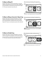
1
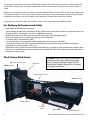
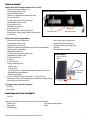
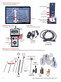
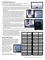
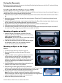
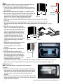
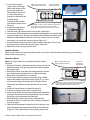
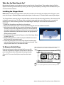
Airtech X-Stream
Wind Tunnel
User Guide
57889 V0311
The Airtech X-Stream Wind Tunnel by Pitsco features adjustable speed and runs quietly. Quality-made and
designed for accuracy, the versatile X-Stream will enhance your science and physics curricula for years to
come.
Whether you’ve purchased the wind tunnel with the Vehicle Platform Sensor (VPS) or the Stinger Mount, this
user guide will help you set up the tunnel, install its accessories, and mount objects in the testing chamber.
Installation instructions are also included for the optional X-Stream Data Acquisition Software.
If you have any questions about this product, please call Customer Service at 800-358-4983.
For Optimum Performance and Safety
• Read, follow, and retain these instructions.
• Do not block the intake bell or the exhaust of the wind tunnel. An obstruction placed in the exhaust stream can
change the flow in the tunnel by as much as 1,000 feet per minute.
• Position the exhaust end of the wind tunnel away from papers and lightweight objects.
• Never push objects of any kind through openings in this equipment.
• To avoid a short in the electrical system:
- Connect all cables and components before plugging this product into a wall outlet.
- Unplug this product from the wall outlet before connecting or disconnecting any cable or component.
• Unplug the wind tunnel when it is not in use.
• Route power cords so that they are not likely to be walked on or pinched by items placed upon or against them.
• If the unit is in need of repair, contact Customer Service at 800-358-4983. Do not attempt to access any internal
components of the system.
The X-Stream Wind Tunnel
Manometer mounting post
Intake bell
FRONT (intake)
CAUTION: If power is lost while the wind tunnel is
operating, the fan motor will not restart when
power is restored until the Fan Motor On/Off
switch on the Handheld Control Unit is switched
off and then switched on.
Testing chamber cover
REAR (exhaust)
Testing chamber
Connection
panel
2
Master switch
Power pack jack
Airtech X-Stream Wind Tunnel User Guide 57889 V0311
Items Included
Wind Tunnel with Vehicle Platform Sensor (VPS)
• Wind tunnel preassembled unit
Vehicle Platform Sensor (VPS)
• Test chamber plastic cover
• Vehicle Platform Sensor
• Thumb nut attached to platform on wind
tunnel intake bell
• 12-volt power pack with power cord
• Detachable AC power cord
• 4 brass thumb nuts
• Handheld control unit
• 4 wire drag links
• Manometer in box with tubing, fluid,
Axle load plates
Brass thumb nuts
thumbscrew, tubing clamp, plastic washer, and
instructions
Wind Tunnel with Stinger Mount
• Wind tunnel preassembled unit •
• Test chamber plastic cover
•
• Stinger Mount instrument
•
• Thumb nut attached to platform on wind tunnel intake bell
•
• Vehicle mounting platform
•
• Handheld control unit
• 12-volt power pack with power cord
• Detachable AC power cord
• 8 brass thumb nuts
• T-wrench
• 4 wire drag links
• Stinger mounting rods:
- three 9" plain
- two 10" plain
- 10" tapped with a 4-40 threaded hole and screw in one end
- Horizontal mounting device
- Platform drag hook • 3 brass wind guard tubes (one each 2", 3", and 4" long)
• Manometer in box with tubing, fluid, thumbscrew, tubing clamp,
plastic washer, and instructions
Brass wind guard support base
Bottle rocket mounting plug
Solid-fuel rocket mounting plug
Drill rod
Set of geometric shapes
Stinger Mount
Vehicle mounting
platform
Stinger Mount
instrument
Brass thumb nuts
X-Stream Data Acquisition Software
• CD-ROM
• Serial cable
Item Required (not included)
• Scissors
If you plan to mount a wing in the wind tunnel, you will need:
• Electric drill
• Fine-point marking pen
• Epoxy glue
• Ruler
• Masking tape
Airtech X-Stream Wind Tunnel User Guide 57889 V0311
3
Manometer Parts and Accessories
Come with VPS and Stinger Mount
Mounting bracket
Fill plug
Tubing
Thumb nut
Plastic washer
Manometer
Tubing clamp
Level vial
Zero set knob
Handheld Control Unit
Mounting post atop
the wind tunnel’s
intake bell
Power Cords
Comes with the wind tunnel
Come with VPS and Stinger Mount
Fan Motor
On/Off
switch
Reset
(Zero/Tare)
button
12-volt power
pack with
power cord
Wind Speed
dial
Detachable
AC power cord
(Fan motor cord)
Mounting Tools and Accessories
All of these items are included with the Stinger Mount. Only the wire drag links are included with the VPS.
10"
tapped
mounting
rod
Platform
drag hook
Drill
rod
10" plain
mounting
rods
Set of
geometric
shapes
Horizontal mounting
device
T-wrench
Solid-fuel
rocket
mounting plug
Wire drag
links
9" plain
mounting
rods
4
Bottle rocket
mounting plug
Brass wind
guard
tubes
Brass
wind guard
support
base
Airtech X-Stream Wind Tunnel User Guide 57889 V0311
Setting Up the Tunnel
1. Place the wind tunnel on a sturdy, level table. Allow the intake bell to hang
over the edge of the table.
2. Plug the handheld control unit into the middle port, which is labeled
“Control Unit,” in the tunnel’s connection panel (Figure 1).
3. Plug the fan motor power cord into the three-prong AC receptacle at the
rear of the connection panel. Then plug the other end of the cord into a
standard 120-V wall outlet. 4. If you have purchased the X-Stream Data Acquisition Software, install it and
connect your computer to the wind tunnel (see instructions below).
Figure 1
Operating the Tunnel
After Setting Up the Tunnel
1. Install the manometer (see page 6).
2. VPS: Follow instructions for Installing the Vehicle Platform Sensor and Mounting a Vehicle on the VPS on page 7.
Stinger Mount: Depending on the object to be tested, the Stinger Mount may be installed before or after
mounting the object in the testing chamber. Follow the instructions for mounting objects that begin on page 7.
3. Turn on the wind tunnel’s master switch. Then, on the handheld control unit, switch on the fan motor. Use the
dial on the control unit to increase or reduce wind speed.
When air begins to move through the tunnel:
– The force that impacts the object in the testing chamber is registered in grams on the handheld control unit’s
LED display. If the X-Stream software is installed, the force will display graphically on your computer screen.
– The manometer simultaneously displays wind speed in feet per minute. See Page 6 for an explanation of manometer readings and a table that you can use to convert those readings into miles per hour.
4. To stop operating the wind tunnel, switch off the fan motor. To shut down the wind tunnel, turn off the master
switch.
Installing the Software
X-Stream Data Acquisition Software provides a colorful graphical depiction of the information displayed on the
hand-held control unit. The data can be viewed or printed for further analysis. Use of the software is optional. The
software is compatible with a Windows 95 or higher operating system.
To Install the Software
1. Insert the CD-ROM in your computer’s CD-ROM drive.
2. Double-click the My Computer icon on your desktop. The My Computer window opens.
3. Double-click the icon for your CD-ROM drive (usually D). The CD-ROM drive window opens. Two program folders
– Stinger Setup and VPS Setup – are displayed.
4. Open the folder for the program you wish to install. The X-Stream setup window opens.
5. Double-click setup.exe and follow the installation instructions that appear on your computer screen. 6. If you wish to install both programs, return to the CD-ROM window (it should still be open), double-click the
other program folder, and repeat Step 5.
To establish connections:
1. Plug the included serial cable into the COM1 or COM2 serial port of your computer. Plug the other end of the
cable into the port labeled 232 in the wind tunnel’s connection panel.
2. Click the Windows Start button.
3. Point to Programs and then double-click either X-Stream Stinger System or X-Stream VPS System. The program
window opens.
4. Click the Options menu and select either COM1 or COM2, whichever one was used in Step 1 to connect the
computer to the X-Stream.
Airtech X-Stream Wind Tunnel User Guide 57889 V0311
5
Installing the Manometer
3" section of tubing keeps
fluid from leaking
The manometer, its tubing, and gauge oil are packaged in a separate box with
instructions. Please read these carefully before installing.
1. Cut off and split a 3" length of the manometer tubing. Insert one of the tubes
into the HIGH and LOW ports on the top left-hand corner of the manometer
(Figure 2). This plugs the ports and keeps oil from leaking during installation. Figure 2
2. Turn the zero set knob counterclockwise until it stops, then turn it clockwise
three full turns.
3. Remove the fill plug. While holding the manometer in its normal
standing position, fill the gauge with gauge oil until the fluid
reaches zero on the scale (about one-third of the bottle). Fill
carefully and slowly because the gauge fills fast. Hint: To prevent
drips, use the other 3" section of tubing as a nozzle for the
gauge oil bottle. If you overfill the gauge, remove excess by
inserting a pipe cleaner through the fill port to blot up excess oil. Figure 3
Figure 4
4. Remove the thumb nut from the manometer mounting post
atop the wind tunnel’s intake bell. Set the manometer on the
post facing the rear of the tunnel. Stack the tubing clamp and
plastic washer (in that order) on the post and replace the
Adjustment
thumb nut (Figure 3).
thumbscrew
5. Remove the 3" section of tubing and replace it with the
manometer tubing. Plug the tube with the red stripe into the
port labeled HIGH and the other tube into the port labeled
LOW (Figure 4). Run the tubing through the tubing clamp
Figure 5
(Figure 5) to secure it.
6. Insert the other ends of the tube into the ports on the side of the intake bell (Figure 6).
Plug the tube with the red stripe into the leftmost port. Plug the plain white tube into
Figure 6
the port next to the testing chamber window.
7. Level the manometer by tilting it slightly to the
Manometer
Manometer
MPH
right or left until the bubble in the manometer’s
Reading
Reading
level vial is centered. When it is level, tighten the
500
5.7
2,300
lower manometer bracket thumbscrew (Figure 5).
MPH
26.1
600
6.8
2,400
27.3
Using the Manometer
700
8.0
2,500
28.4
The included manometer displays air velocity in
thousands of feet per minute (FPM x 1,000). The
gauge displays numbers from 0 (no velocity) to
7 (7,000 feet per minute) (Figure 7). The marks
along the gauge’s path divide the velocity into
finer increments. From 500
to 1,000 feet, the marks
indicate increments of 100
feet. From 1,000 to 2,000
feet, the marks indicate 1,000
foot increments. From 2,000
upward, the marks indicate
2,000 foot increments.
800
9.1
2,600
29.5
900
10.2
2,700
30.7
1,000
11.4
2,800
31.8
1,100
12.5
2,900
33.0
1,200
13.6
3,000
34.1
1,300
14.8
3,100
35.6
1,400
15.9
3,200
36.4
1,500
17.0
3,300
37.5
1,600
18.2
3,400
38.6
1,700
19.3
3,500
39.8
1,800
20.5
3,600
40.9
1,900
21.6
3,700
42.4
2,000
22.7
3,800
43.2
2,100
23.9
3,900
44.3
2,200
25.0
4,000
45.5
Figure 7
Use the handy table at right to
convert feet per minute to miles per hour.
6
Airtech X-Stream Wind Tunnel User Guide 57889 V0311
Storing the Manometer
Before storing the manometer, disconnect the tubing. Plug the high and low ports with the 3" section of tubing.
This will keep the fluid from leaking.
Installing the Vehicle Platform Sensor (VPS)
The Vehicle Platform Sensor (VPS) simultaneously measures lift forces on front and rear axles and overall drag on a
vehicle placed in the testing chamber of the wind tunnel.
1. Make sure the power pack is disconnected from the jack at the rear of the wind tunnel and the master switch is
off.
2. Remove the plastic cover from the top of the testing chamber. Thread the VPS’s cable through the hole at the
rear of the chamber.
3. Angle the VPS into the chamber. Insert its legs into the holes in the floor of the chamber. Attach thumb nuts to
the legs of the VPS that protrude underneath the testing chamber.
4. Plug the VPS cord into the port labeled “Instrument” in the wind tunnel’s connection panel.
5. Plug the power pack into the jack at the rear of the wind tunnel.
6. Locate the power pack and its cord. Plug the cord into the power pack and the jack into the port at the rear of
the wind tunnel. Then, plug the power cord into a standard wall outlet.
Mounting a Dragster on the VPS
1. Attach a drag link to a dragster’s eye hook. Place the
dragster on the VPS and loop the link over the mounting
hook at the front of the platform.
Other Vehicles: The user must devise a method of attaching
a drag link to vehicles other than dragsters.
2. Slide the axle load plates so that the wheels of the dragster
are centered on them. This is an important step that
assures the accuracy of your measurements.
Mounting an Object on the Stinger
Figure 8
Vehicles
1. Install the Stinger Mount as directed on page 10.
2. Remove the plastic cover from the top of the testing
chamber.
3. Angle the vehicle mounting platform and lower it into the
testing chamber so that the hole in the platform faces
toward the intake bell (Figure 9). Insert the legs of the
platform into the holes on the floor of the chamber. Attach
thumb nuts to the legs of the platform underneath the
testing chamber.
4. Insert the platform mounting hook through the hole in the
platform until its hook rests on the platform.
Figure 9
5. While holding the hook slightly above the surface of the
platform, reach underneath the testing chamber and insert the T-wrench into
the set collar underneath the Stinger Mount and tighten it (Figure 10).
6. Attach a drag link to the eye hook underneath the dragster.
Note: The user must devise a method of attaching a drag link to vehicles
other than dragsters. Place the dragster or other vehicle on the Stinger Mount.
Loop the drag link over the the hook in the mounting rod.
7. Replace the testing chamber plastic cover.
Airtech X-Stream Wind Tunnel User Guide 57889 V0311
Figure 10
7
length
Wings
Note: To mount a wing in the wind tunnel, a mounting rod must
Recommended
be inserted into the wing’s edge and glued in place.
depth: 1/2 chord
1. Gather the wing, an electric drill, masking tape, ruler, marking
of wing
pen, epoxy glue, the drill rod, one of the 9" mounting rods, and
the T-wrench.
Mark
2. Measure the chord of your wing (Figure 11). Divide it by two. Masking tape
wrapped just
3. Measure the resulting distance from the pointed end of the drill
chord
below mark
rod and make a mark. Wrap a short piece of masking tape
Figure 11
around the rod so that its edge is aligned with the mark
(Figure 12). This will serve as a depth guide for drilling.
4. Chuck the rod into the drill. Mark the drill point on your wing at 25 percent of the chord
(Figure 13).
5. Very carefully drill into the wing edge (Figure 14). Drill slowly and straight so that the drill
rod does not exit the wing surface. When the masking tape contacts the wing edge, stop Figure 12
drilling.
6. With the ruler, measure the wing length
(Figure 11) and divide by two. Measure and
mark the resulting distance from one end
of the 9" mounting rod. Put a few drops of
epoxy on the end of the rod and insert it
into the drilled hole. Push it until the mark
is aligned with the wing edge. Set the
25% of chord
wing/rod assembly aside and allow the
chord
epoxy to dry for 10 minutes. An example of
Figure 13
Figure 14
a finished mounted wing is pictured in
Figure 15.
Leading
7. Remove the plastic cover from the testing
edge
chamber and take out the vehicle
mounting platform if it is inside the
chamber.
8. Install the Stinger Mount as directed pm
page 10.
9. Insert the rod of the mounted wing
through the middle hole in the floor of the
testing chamber into the Stinger Mount.
The leading edge of the wing should face
the intake bell of the wind tunnel. While
Figure 16
Figure 15
holding the object in place, reach
underneath the chamber, insert the T-wrench into the set collar, and tighten it to secure the mounting rod
(Figure 10 on previous page). Replace the testing chamber cover. The wing is ready to test (Figure 16).
Rockets (Figure 17)
Note: The Stinger Mount is not attached until the rocket is
mounted.
1. Gather the T-wrench, horizontal mounting device, bottle rocket
plug, thumb nut, wind guard support base, and the wind guard
tube that best covers the rod of the horizontal mounting device
when the rocket is positioned at half the height of the test
chamber.
2 Remove the plastic cover from the testing chamber. Take out the
vehicle mounting platform if it is inside the chamber. Remove the
Stinger Mount if it is attached.
8
Figure 17
Airtech X-Stream Wind Tunnel User Guide 57889 V0311
View: Looking down into the
Wind guard support
3. Insert the wind guard
testing chamber from above.
base mounted here
support base in the large
hole on the bottom of the
wind tunnel above the
Stinger Mount (Figure 18).
Its screw will protrude
Figure 19
through the bottom of the
chamber. Reach
underneath the chamber
and thread a thumb nut on
Figure 18 – Position of brass wind guard support base
the screw.
for mounting rockets. Figure also shows installed
4. Install the Stinger Mount
Stinger Mount positioned to measure drag on a rocket.
as directed on page 10.
5. Slide the wind guard tube onto the wind guard support base.
6. Insert the rod of the horizontal mounting device through the wind guard tube
into the Stinger Mount. The short end of the rod should face toward the intake
bell. Reach underneath the chamber, insert the T-wrench into the set collar,
and tighten it to secure the mounting device (Figure 19).
7. Insert the bottle rocket plug into the mouth of the bottle rocket. Then, insert Figure 20
the plug onto the horizontal mounting device (Figure 20).
8 Replace the plastic testing chamber cover.
Solid-Fuel Rockets
Follow the instructions for mounting bottle rockets but use the solid-fuel rocket mounting plug instead of the
bottle rocket mounting plug.
Geometric Objects
Note: The Stinger Mount is not attached until the rocket is
mounted.
1. Gather the T-wrench, horizontal mounting device, thumb nut,
geometric object, wind guard support base, and the longest
wind guard tube.
2 Remove the plastic cover from the testing chamber. Take out
the vehicle mounting platform if it is inside the chamber.
Remove the Stinger Mount if it is attached.
3. Insert the wind guard support base into the large, middle
hole on the bottom of the wind tunnel (Figure 21). Its screw
will protrude through the bottom of the chamber. Reach
underneath the chamber and thread a thumb nut on the
screw.
4. Install the Stinger Mount as directed on page 10.
5. Slide the wind guard tube onto the support base.
6. Insert the rod of the horizontal mounting device through the
wind guard tube and into the Stinger Mount. Position either
the long or short end toward the intake bell.
7. While holding the rod in place, reach underneath the
chamber, insert the T-wrench into the set collar, and tighten it
(Figure 19 above).
8. Select one of the geometric objects and slip it onto the end
of the horizontal mounting device that faces the intake bell
(Figure 22). Then, replace the testing chamber plastic cover.
Airtech X-Stream Wind Tunnel User Guide 57889 V0311
View: Looking down into the
testing chamber from above.
Wind guard
support base
mounted here
Figure 21 – Position of brass wind guard support base
for mounting geometric shapes. Figure also shows
Stinger instrument installed to measure drag.
Figure 22
9
What Are the Wind Guards For?
Mounting rods become sensing devices when inserted into the Stinger Mount. They produce drag just like the
object in the testing chamber does. By covering the sensing rod completely, rod drag will not be reflected in your
wind tunnel measurements.
Installing the Stinger Mount
Note: Before installing the Stinger Mount, read the instructions for mounting your object on the Stinger. In some
cases, the Stinger is attached before mounting the object; in other cases, it is attached after mounting the object.
The Stinger Mount measures drag on mounted objects positioned inside the testing chamber. It also measures lift
or drag on mounted wings. The Stinger slides onto posts underneath the testing chamber and is secured with
thumb nuts. Its exact mounting position varies depending on the objects to be tested and the force to be
measured.
1. Locate the Stinger Mount and four brass thumb nuts.
2. Make sure that the power pack is disconnected from the jack at the rear of the wind tunnel.
3. While looking through the glass panel at the bottom of the testing
chamber, position the Stinger Mount on the posts underneath the
chamber according to the object and force to be measured (see the
figure from whichever of the next four sections are appropriate for
the object being tested).
4. Screw a thumb nut onto each of the posts to hold the Stinger Mount
in place (Figure 23).
5. Plug the Stinger Mount’s cable into the port labeled Instrument in
the wind tunnel’s connection panel.
Figure 23
6. Locate the power pack and its cord. Plug the cord into the power
pack and the jack into the port at the rear of the wind tunnel. Then,
plug the power cord into a standard wall outlet.
To Measure Vehicle Drag
View: Looking down into the testing chamber and through the glass
panel at the bottom of the chamber. The intake bell is at left.
Face the wind tunnel so that the intake bell is on your left.
Slide the Stinger Mount lengthwise onto the four frontmost
posts that protrude from underneath the testing chamber
(Figure 24). The arrow should point away from the intake
bell.
Figure 24 – Proper Stinger Mount position for measuring vehicle
drag
10
Airtech X-Stream Wind Tunnel User Guide 57889 V0311
To Measure Wing Lift
View: Looking down into the testing chamber and through the
glass panel at the bottom of the chamber. The intake bell is at left.
Face the wind tunnel so that the intake bell is on your left.
Slide the Stinger Mount crosswise onto the four middle posts
that protrude from underneath the testing chamber (Figure
25). The arrow should point away from you. Figure 25 – Proper Stinger Mount position for measuring wing lift
To Measure Wing or Geometric Shape Drag
View: Looking down into the testing chamber and through the
glass panel at the bottom of the chamber. The intake bell is at left.
Face the wind tunnel so that the intake bell is on your left.
Slide the Stinger Mount lengthwise onto the four middle
posts that protrude from underneath the testing chamber
(Figure 26). The arrow should point away from the intake bell.
Figure 26 – Proper Stinger Mount position for measuring wing or
geometric shape drag
To Measure Rocket Drag
View: Looking down into the testing chamber and through the glass
panel at the bottom of the chamber. The intake bell is at left.
Face the wind tunnel so that the intake bell is on your left.
Slide the Stinger Mount lengthwise onto the four rear posts
that protrude from underneath the testing chamber (Figure
27). The arrow should point away from the intake bell.
Figure 27 – Proper Stinger Mount position for measuring rocket
drag
Airtech X-Stream Wind Tunnel User Guide 57889 V0311
11
P.O. Box 1708 • Pittsburg, KS 66762
www.pitsco.com
Toll-Free Orders 800-835-0686
12
Airtech X-Stream Wind Tunnel User Guide 57889 V0311