1
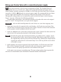
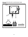
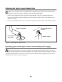
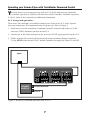
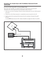
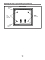
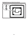
72-4131-250
8/03
Dumbo Pylon
Owner’s Manual
© Disney
Congratulations
ongratulations on your purchase of the Lionel Dumbo Pylon! Watch as Dumbo circles the
tower. Mrs. Jumbo and Timothy Q. Mouse peer out of the illuminated windows at the base
of the pylon.
C
Dumbo Pylon Inventory
•
•
•
•
Pylon
Dumbo figure
Support arm
Switch
• Two green wires
• Owner’s Manual
• Service Center list
Table of contents
Wiring your Dumbo Pylon with a conventional power supply
3-4
Installing your Dumbo Pylon
5
Attaching the figure to your Dumbo Pylon
6
Operating your Dumbo Pylon with a conventional power supply
6
Operating your Dumbo Pylon with TrainMaster Command Control
Replacing the lamp in your Dumbo Pylon
7-8
9-11
Limited Warranty/Lionel Service
12
The following Lionel marks may be used throughout this instruction manual and are protected under
law. All rights reserved.
Lionel®, TrainMaster®, Odyssey®, RailSounds®, CrewTalk™, TowerCom™, DynaChuff™,
StationSounds™, Pullmor®, ElectroCoupler™, Magne-Traction®, CAB-1 Remote Controller®,
PowerMaster®, Lionel ZW®, ZW®, PowerHouse®, TMCC®, Lionelville™, Lockon®
The name FasTrack® is used with permission from Pitsco, Inc.
2
Wiring your Dumbo Pylon with a conventional power supply
iring your accessory is the first step in preparing for flight. The Dumbo Pylon will
operate best at 12-18 volts (AC), and it can be powered through track power with a
Lionel Lockon (available separately, 6-62900), or a FasTrack Accessory Power Wire (available
separately, 6-12053), OR through an accessory power supply. We recommend that you choose
a power supply that will allow you to increase or decrease the voltage to the accessory.
Changing the voltage allows you to control the speed at which the figure circles the pylon.
Figure 1 on page 4 illustrates the following procedure.
To make proper connections, you need the insulation at the ends of the wires to be stripped
back 1/4” to 3/8”. To strip the wires, use a pair of wire strippers.
W
Caution!
Only an adult should perform this task! Always use care when stripping wires.
1. Attach one wire to the #1 terminal of the track Lockon, a FasTrack Accessory Power Wire,
OR the Power/A terminal on the accessory power supply. Connect it to one of the terminals
on the separate switch (included with this accessory).
2. Attach an additional wire to the other terminal on the switch. Connect the other end of this
wire to one of the spring-clip terminals at the bottom of the pylon.
Note! To make the spring-clip terminal connections, press down on the “springy” top of
the terminal clip so that a metal loop is formed. Slide the bare end of the wire into
the exposed loop. Release pressure on the terminal clip, allowing the crimped metal
to pinch the end of the wire in the metal loop. Give a little tug on the wire to check
if the hold is secure.
3. Attach another wire to the #2 terminal of the track Lockon, a FasTrack Accessory Power
Wire, OR the Common/Ground/U terminal on the accessory power supply. Connect it
directly to one of the spring-clip terminals at the bottom of the pylon.
At this point, your accessory is wired for power. The next section explains how to operate this
accessory in a conventional (non-TrainMaster Command Control) environment.
3
Wiring your Dumbo Pylon with a conventional power supply
(continued)
Mounting
holes
Mounting
holes
U
U
A
A
U
A
POWER
SUPPLY
FasTrack Accessory Power Wire
Figure 1. Wiring for conventional operation
4
Installing your Dumbo Pylon
hoose a flat, level area on your layout for the accessory. Secure this accessory to your
layout with four screws (not included) using the holes near the corners of the base. Be
sure to wire your accessory before you secure it to your layout—the wire terminals are on the
underside of the base. Keep in mind that Dumbo flies in a circle with diameter of 30”. The
flight path must be kept clear.
C
5
Attaching the figure to your Dumbo Pylon
C
omplete the assembly of your Dumbo Pylon by attaching the Dumbo figure and support
rods to the structure. Figure 2 illustrates the following procedure.
1. Note that the supporting rod has different shaped ends. Insert the flattened end of the
support rods into the tube protruding from the top of the pylon. Refer to the diagram for
further assistance.
2. Insert the D-shaped ends of the wires into the openings in the bottom of the Dumbo figure.
Support rod (bottom)
Mounting hole, bottom
of Dumbo
Mounting hole on
top of pylon
Support rod (top)
Figure 2. Installing the support rods
Operating your Dumbo Pylon with a conventional power supply
djust the voltage to the accessory to control the speed at which Dumbo circles the tower.
Increasing the voltage will cause Dumbo to circle faster; decreasing the voltage will cause
Dumbo to travel slower. To turn the accessory off, turn off the power supply or use the switch
attached to the wires in Step 1 on page 3.
A
6
Operating your Dumbo Pylon with TrainMaster Command Control
ou may choose to wire your accessory with an SC-2 Switch and Accessory Controller
(available separately, 6-22980) or the Accessory Switch Controller (available separately,
6-14182). Refer to these manuals for additional information.
Y
SC-2 wiring and operation
Three wires (not included) are needed to connect your Pylon to the SC-2 and a separate
accessory transformer. We recommend using 22 gauge wire. Refer to Figure 3.
1. Attach one wire to the transformer Common/Ground/U terminal and connect it to the
accessory COMM (common) position on the SC-2.
2. Connect one of the Pylon terminals to the accessory ON/OFF toggle position on the SC-2.
3. Finally, connect the remaining Pylon terminal to the transformer Power/A terminal.
Use the AUX2 button on your CAB-1 Remote Controller to toggle the Pylon ON and OFF.
Pylon
ACC1
ACC2
POWER
SUPPLY
Common/Ground/U
Power/A
Figure 3. Wiring for Command operation with an SC-2
7
ACC1
ACC2
Operating your Dumbo Pylon with TrainMaster Command Control
(continued)
Accessory Switch Controller wiring and operation
Three wires (not included) are needed to connect your Pylon to the Accessory Switch
Controller (ASC) and a separate accessory transformer. Refer to Figure 4.
1. Attach one wire to the transformer Power/A terminal and connect it to the COMM terminal
on the ASC.
2. Connect one of the Pylon terminals to a numbered accessory terminal on the ASC.
Py
lo
n
3. Finally, connect the remaining Pylon terminal to the transformer Common/Ground/U
terminal.
Use the AUX2 button on your CAB-1 Remote Controller to toggle the Pylon ON and OFF.
POWER
SUPPLY
Common/Ground/U
Power/A
Figure 4. ASC connections
8
Replacing the lamp in your Dumbo Pylon
our Pylon is illuminated by one 18-volt lamp. During the course of normal operations,
this lamp may require replacement. Follow these steps to replace the lamp with Lionel
part no. 612-3011-311.
Y
1. Lift the support arm out of the tubes at the top of the pylon. Also, remove any screws
securing the base to your layout.
2. Remove the four base screws from the underside of the base with a small Phillips-head
screwdriver and lift away the roof and pylon tower. Refer to Figure 5 on page 10 for the
location of the screws.
3. Locate the lamp in its small, black fixture. Carefully pull the lamp straight up and out of
the socket. Refer to the Figure 6 on page 11 for the lamp location.
4. Install the replacement lamp. Line up the bottom of the bulb with the socket and carefully
push the lamp down into place.
5. Reassemble the Pylon, following these steps in reverse order.
9
Replacing the lamp on your Dumbo Pylon (continued)
Base of the Pylon
Mounting
holes
Roof
screws
(recessed)
Base
screws
(recessed)
Mounting
holes
Figure 5. Screw locations
10
Replacing the lamp on your Dumbo Pylon (continued)
Interior of the building with the roof removed
Figure 6. Lamp location
11
Limited Warranty/Lionel Service
his Lionel product, including all mechanical and electrical components, moving parts, motors and
structural components, except for light bulbs, is warranted to the original consumer-purchaser, for one
year against original defects in materials or workmanship when purchased through an authorized Lionel
merchant.
This warranty does NOT cover normal wear and tear, light bulbs, defects appearing in the course of
commercial use, or damage resulting from abuse or misuse of the product by the purchaser. Transfer of this
product by the original consumer-purchaser to another person voids this warranty. Modification of this product
voids this warranty.
Any warranted product which is defective in original materials or workmanship and is delivered by the
original consumer-purchaser to Lionel L.L.C. or an authorized Lionel L.L.C. Service Center, together with proof of
original purchase will, at the option of Lionel L.L.C., be repaired or replaced, without charge for parts or labor.
In the event the defective product cannot be repaired, and a replacement is not available, a refund of the original
purchase price will be granted. Any products on which warranty service is sought must be sent freight or postage
prepaid, as transportation and shipping charges are not covered by the warranty.
T
In no event shall Lionel L.L.C. be liable for incidental or consequential damages.
Some states do not allow the exclusion or limitation of incidental or consequential damages, so the above
exclusion may not apply to you.
This limited warranty gives you specific legal rights, and you may have other rights which vary from state
to state.
Instructions for Obtaining Service
If service for this Lionel L.L.C. product is required, bring the item, along with your dated sales receipt and
completed warranty information to the nearest Authorized Lionel Service Center. Your nearest Lionel Service
Center can be found by calling 1-800-4-Lionel, or by accessing our Website at www.lionel.com.
If you prefer to send your product back to Lionel L.L.C. for repair in Michigan, you must first call
586-949-4100 or FAX 586-949-5429, or write to Customer Service, P.O. Box 748, New Baltimore, MI
48047-0748, stating what the item is, when it was purchased and what seems to be the problem. You will be
sent a return authorization letter and label to ensure your merchandise will be properly handled upon receipt.
Once you have received your return authorization and label, make sure that the item is packed to prevent
damage during shipping and handling. We suggest that you use the product’s original packaging. This
shipment must be prepaid and we recommend that it be insured.
Please make sure you have followed all of the above instructions carefully before returning any
merchandise for service. You may choose to have your product repaired by one of our Authorized Lionel Service
Centers after its warranty has expired. A reasonable service fee will be charged.
Warranty Information
Please complete the information below and keep it, along with your dated sales receipt. You must present
this and your dated sales receipt when requesting warranty service.
Name ________________________________________________________________________
Address ______________________________________________________________________
Place of Purchase ________________________________________________________________
Date of Purchase ________________________________________________________________
Product Number ________________________________________________________________
Product Description ______________________________________________________________
©2003 LIONEL L.L.C., CHESTERFIELD, MI 48051-2493
UNITED STATES OF AMERICA
PRINTED IN CHINA