1
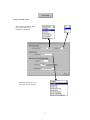
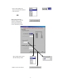
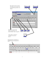
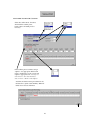
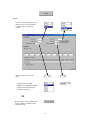
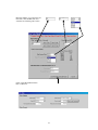
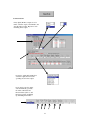
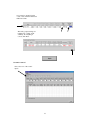
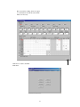
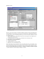
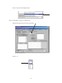
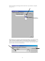
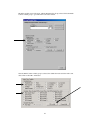
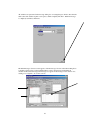
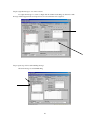
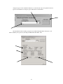
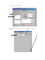
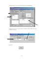
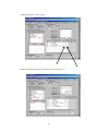
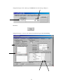
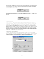
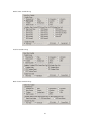
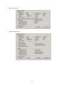
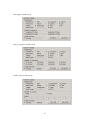
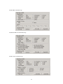
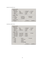
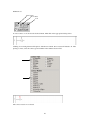
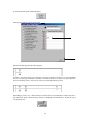
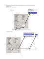
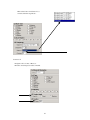
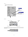
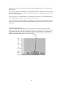
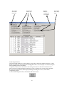
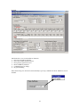
Fusion Configuration Program User’s Guide INTRODUCTION PROGRAM OVERVIEW SCREEN DETAILS File New Summary High Speed Counter Messages / Screens Parameter Sets Ladder Diagram General Open Close Save Save As Print Send Receive Exit Setup Comm Setup Options Tools Manual Communications 57590-902-02 2 2 2 2 2 3 3 18 40 45 55 59 59 60 60 60 61 61 62 62 62 62 63 63 About this guide This is the companion document to the Durant Fusion configuration software. Although the configuration software can be used to read or edit existing Fusion programs, its primary function is for creating new programs and downloading them to Durant Fusion controls. This guide explains how to use the software, not how to develop the particular Fusion program. For information on the operation of the Fusion control, and on the programming selections available, consult the Fusion User and Operation manual, Durant part number 57550-901. The “Applying the Fusion” chapter of that manual, provides a step by step process for developing a program to meet the requirements of the specific application. Each step in the process refers to one or more destinations in the software that may need to be addressed. Each step also provides reference pages in the manual which explain the terminology, the operation of individual elements of the control, and their interactions with other elements. About the configuration software The Fusion configuration software is available free of charge via a link on our website (www.durant.com), or on CD for a reasonable charge (part number 57590-400). In either case, the setup.exe program installs the software in the pc. By default, a folder named “Fusion” is created in Program Files. The Fusion folder consists of two folders, “Docs” and “Icons”. The individual configuration programs are saved with a .fsn extension as files in Docs. Files received in e-mail or read from disk should be saved to Program Files / Fusion / Docs, and then opened from the Fusion configuration program. Program overview The program consists of four segments, File, Setup, Tools, and Help. File: the actual file handling functions of this program, including creating new files, and sending and receiving existing files. Setup: allows selection of comm port 1 or 2, auto backup interval and number of backups saved, and highlight color. Tools: the manual communication tool, which allows serial commands to be formatted and sent, and responses to be displayed. Help: the standard Windows Help function. Self explanatory. File, Setup, and Tools in detail FILE New Choose the File New menu command to start a new configuration program. 2 Summary The summary screen can be used to identify the purpose of the program, it’s date of origin and author, and a fairly detailed explanation of how it works. HSC Configuration The high speed counter is broken down into its component elements (main counter, batch counter, totalizer, and ratemeter) in order to program the HSC in manageable pieces. Not all Fusion applications will use the High Speed Counter. This tab may be skipped for those programs. If the high speed counter is required, access the needed functions via these buttons. The I/O Overview button tabulates each input and output assignment for a quick visual summary. 3 MAIN COUNTER SETUP Select count mode and resolution. Note: X4 resolution only available for quadrature. If the high speed reset is to be used (I17), select its function. 4 Select count decimal point location, and enter the calculated count scale factor, OR Click on the Count Scale Calculator button to have the scale factor calculated by entering the decimal point location and Pulses per Item Select decimal point location, and enter Pulses per Item Finally, click on Save button 5 Select to either reset or save any portion of a scaled count if the main counter auto recycles. When all main counter selections have been made, click Done. This will restore the HSC main menu screen. 6 MAIN PRESETS FUNCTIONS Enter the Maximum Preset value allowed to the operator and select the final preset needed Enabling one or more presets activates the remaining functions 7 If more than one preset is chosen, select the preset to be active after reset and after the parameter set is changed With Preset 1 selected, make Prewarn, Auto Recycle, and Increment Batch counter assignments Assign outputs to turn ON, or turn OFF, or No Action at Preset 1 Repeat the function assignments for the remaining presets and prewarn, if used 8 Preset functions are tabulated for a quick, visual summary Unchecking Device Display Format changes the 1/0 designation to On/Off When all preset / prewarn functions are assigned, click Done. The actual preset values may be entered in Parameter Sets, or may be editable on the display. 9 TOTALIZER AND BATCH COUNTER Select the totalizer mode, if needed, and enable the totalizer preset, batch counter, and batch preset as necessary If the totalizer preset is enabled, assign outputs to it as appropriate. If the batch preset is enabled choose auto recycle and outputs as appropriate. The actual preset values may be entered in Parameter Sets, or may be editable on the display. Totalizer and batch counter preset functions are tabulated for a quick, visual summary. When all functions are chosen, click Done 10 RATE If rate is not needed, skip this screen. Enable rate, if needed, and enable rate high and/or low presets if needed. Enter rate update and rate zero times Scaling can be done either manually, by selecting the decimal point location and entering the calculated scale factor, OR The scale factor can be calculated and saved by clicking on the Rate Scale Calculator button 11 Enter the number of seconds in the rate time units, enter the PPI value, and select the rate decimal point location Click on Save Rate DP and Scale Factor when done 12 If rate presets are enabled, select one preset Assign outputs to be latched On or Off, or Compared at each update as appropriate When all the necessary outputs have been assigned, click Done. The actual preset values may be entered in Parameter Sets or may be editable on the display. 13 OUTPUT MODE If any digital (K1-K7) outputs are to be timed, select the output, select Enable, and enter the timeout value. Repeat for each remaining timed output. For analog outputs K8 and K9, first select the output, then select the operating mode for that output For an analog setpoint output, enter the Timeout (optional), On Value, Off Value and Prewarn Value (all in %, and Prewarn optional), and Ramp Up and Ramp Down times 14 For an analog output following count or rate, enter the Offset and Full Scale values The analog output settings are tabulated for a quick, visual summary. If everything is correct, click Done CONTROL INPUTS First, select one of the control inputs 15 Assign control functions to the input. Up to 13 functions can be assigned to a single input, however most inputs will only be assigned one function. Repeat the process for each control input that is needed to perform a control function. Input functions are tabulated for a quick, visual summary. When all input control functions have been programmed, click Done I/O OVERVIEW TABLE The I/O Overview button accesses a table which shows all HSC functions for each input, trigger events for each output, and shows which output coils have been used in the ladder logic. This summarizes which resources have been used, and for what purpose. 16 This screen allows editing. Select an output or count function and edit the events which affect it as necessary. Click Done to return to the HSC main menu 17 Messages / Screens Messages / Screens will normally be programmed after HSC Configuration and the Ladder Diagram have been programmed. A list of messages is a by-product of following the user’s manual application guide in developing a Fusion program. Programming the Messages / Screens menu with the configuration software is a seven step process: 1. Since it is unlikely that any of the default messages will be exactly right for the real application, all existing messages will be deleted. 2. Convert the message list into screen layouts, and determine the screen display format. 3. Set the number of operator scrollable screens. 4. Pick a message type and message number. 5. Assemble the actual message. 6. Assign the message to one or more screens. 7. Repeat steps 4-6 for each remaining message. The procedure will be shown in detail in the context of an example. In the course of the example, several messages which include variables will be programmed. There are hundreds of HSC and ladder data items that are considered variables. These are not all shown on a single screen using the configuration software, but are accessed by branching from general categories of data items to specific items (variables). The paths to specific variables are shown following the example as a reference. 18 MESSAGES / SCREENS EXAMPLE Using the Applying the Fusion section of the Fusion User and Operation manual for programming a unit in a batch control application, the following list of messages was generated: 1. main count value 2. preset 1 3. “batch complete” status message 4. batch count 5. totalizer value 6. Start, Stop, and Resume key identifiers 7. rate in GPM when a batch is running (ladder message) 8. “OVERFLOW” alarm message (ladder message) Step 1: delete the default messages Click the Delete Run/LD Msg’s button Click the Yes button 19 All run and ladder messages will clear Step 2: convert the message list into screen layouts and determine the display screen format. The main count value, preset 1, batch complete, and rate messages will be on one screen, and the batch count and totalizer will be on a second screen. The key identifiers and overflow alarm message will appear on both screens. The messages will be laid out on each screen as in the table below: Row 1 Row 2 Row 3 Row 4 Screen 1 Main count value Preset 1 / OVERFLOW Batch complete / rate Start, Stop, Resume Screen 2 Batches (text) Batch count value /OVERFLOW Totalizer value Start, Stop, Resume In this example, four lines are required per screen. Click the Display Format drop down button to select the format. 20 Select one of the four line display formats. Step 3: set the number of operator scrollable screens. Click the View Key Screen Scroll drop down button. Select 1 to 2. 21 Step 4: pick a message type and message number. Run message #1 is as good a place to start as any. Step 5: assemble the message. Click the Edit Msg button 22 The message editing screen will appear. Click on the Line No. drop down button to assign this message to line 1. Then click the cursor into the left-most space in the message editing box. Seven characters will fit on line 1 according to the display format chosen. More characters can be included, but the character size will be automatically reduced to accommodate all characters programmed. Since the message on line 1 is the main count value (which is seven characters), and since the main count value is a variable, click on the Add Variable button. 23 The main variable screen will appear, with the Parameter Set Group selected. Select the Main Counter variable group to get to the main count value variable. Once the Main Counter variable group is selected, the default item selected is the main count value. Click on the OK to Add button. 24 All variables are represented in the message editing box as rectangular space holders. Note that the main count value variable requires seven spaces, which completely fills line 1. With run message 1 completely assembled, click Done. The main Messages / Screens screen appears, with run message 1 shown in the Current Msg list as a variable assigned to line 1. The Variable Name box below the message list identifies all variables in the selected message. The message also appears in the message screen selection box, waiting to be assigned to one or more screens. 25 Step 6: assign the message to one or more screens. To assign run message 1 to screen 1, simply click in column 1 in the Msg’s by Screen box. The message will then appear in the screen preview box for all screens that it is assigned to. Step 7: repeat steps 4-6 for each remaining message. Select run message 2, and click Edit Msg. 26 Assign message 2 to line 2. With ten characters to work with, and only seven required for Preset 1, type in a text identifier “P” and space, space. Then click on Add Variable. Select the Main Counter variable group, then select CPS (Current Parameter Set) Preset 1, and make it editable by the operator by selecting View/Edit. Then click OK to Add. 27 With the message completely assembled, click Done. Assign run message 2 to screen 1. 28 Select run message 3, and click Edit Msg. Assign the message to line three, then type the text message into the message editing box. Click Done. 29 Assign the message to screen 1. Then select run message #4, and click Edit Msg. Assign the message to line four. Type in the text to identify keys B7, B8, and B10 as Start, Stop, and Resume, respectively. Click Done. 30 Assign this message to screens 1 and 2. Add the remaining run messages in the same manner as messages 1-4. 31 There are two remaining messages, both ladder messages. Assume that the OVERFLOW message is D15, and the Rate message is D16. Select Ladder Diagram 9-16 in the Message Type and Range box. Then select ladder message 15 and click Edit Msg. 32 Assign the message to line 2, then type “OVERFLOW” into the message editing box. Click Done. Assign the message to screens 1 and 2. Then select ladder message 16 and click Edit Msg. 33 Assign ladder message 16 to line 3. Then type in identifying text (Flow Rate), space, space, add the rate variable, and rate units text. Click Done. Assign the message to screen 1. All messages have now been programmed. Note that the screen preview box for screen 1 shows that more than one message is programmed for lines 2 and 3, as indicated by the arrows to the right of these lines. Clicking on the arrow buttons will cause the other messages assigned to these lines to be previewed. 34 The final feature of the Messages / Screens screen is the displayed terms for the status of bits. Bits are the states of the ladder contacts and coils, which may be displayed in messages as variables. By default, the states are designated “ON” and “OFF”. These designations can be changed to any three printable ASCII characters, such as “1” and “0”, or “Yes” and “No”. VARIABLE GROUPS There are hundreds of HSC and ladder data items that can be displayed. Many of these variables are editable, such as presets. When these variables are included in a message, they may be selected as either VIEW ONLY, or as VIEW EDIT. If the operator needs to be able to change the value for a variable, it should be displayed as VIEW EDIT. All data items that can be displayed as variables are shown below. Rather than list every variable on a single screen, variables are grouped according to function. For instance, the main counter presets are part of the main counter variable group. To locate a variable for a message, first select the group that it is in. Then all the individual variables that are in the selected group will appear, and the specific variable can be chosen to add to the message. For those variables that are editable, the VIEW ONLY or VIEW EDIT choice is made at this time. VARIABLE LOCATOR REFERENCE When the Add Variable button is clicked while programming a message, the list of variable groups appears. By default, the Parameter Set variable group is shown. There are only two variables in this group. Click on the one needed for the message, and select VIEW ONLY or VIEW EDIT to add one of these variables to the message. For any other variable, first select the variable group that it is in. 35 Main Counter Variable Group Totalizer Variable Group Batch Counter Variable Group 36 Rate Variable Group Outputs Variable Group 37 Analog Inputs Variable Group Analog Comparators Variable Group Ladder Counters Variable Group 38 Ladder Timers Variable Group Ladder Real Time Clock Variable Group Ladder Contacts Variable Group 39 Ladder Coils Variable Group Ladder Bits Variable Group 40 HSC Parameter Sets A parameter set consists of the values for the ten presets and the two offsets used by the Fusion. Most configuration programs that use the Fusion’s high speed counter will use at least one parameter set, although very few programs will use all ten presets. The ten presets and two offsets, and the values that make up the default parameter set. There are two reasons to address parameter sets in the configuration program. First, one or more preset or offset values used in the program must be changed from the default value and those presets are not to be editable by the operator. Second, the configuration program may be set up to use more than one parameter set. To change preset / offset values from default, enter the new value in the appropriate preset editing box in the Modify Parameter Set Value field. The new value is saved when Enter is pressed, or when another field is selected. 41 If the configuration program is to use more than one parameter set, first select the number of parameter sets needed. The selected number of parameter sets opens for value entry 42 For each parameter set, enter those preset values which are not the same as those in parameter set 1. 43 Finally, select Current Parameter Set for those presets whose values change from one parameter set to the next, and select Parameter Set 1 Only for those presets whose values remain the same as for parameter set 1. The values used by the Fusion for presets 1, 2, and 3 in parameter sets 1-4 are shown in the table below. Parameter set 1 Parameter set 2 Parameter set 3 Parameter set 4 Preset 1 10.00 11.00 12.00 13.00 Preset 2 12.00 13.00 14.00 15.00 44 Preset 3 50.00 50.00 50.00 50.00 Ladder Diagram The default ladder diagram is empty. Up to 100 rungs may be programmed, with a maximum of six contacts and one coil per rung. The Fusion processes the ladder from rung 1 up to the first open rung. It does not process past an open rung, even if there are programmed rungs past the open rung. Ladder Editor Features Element Tools Contact #1 Position Wire Tools Contact #6 Position Wire Positions 1-6 45 Element Selector Edit Tools Coil Position Element Tools NO Contact NC Contact Coil To add a contact or coil, click on the desired element. Then click on the appropriate ladder position. Clicking on an existing element will replace it with the new element. New contacts will default to I1. After placing a contact, select the contact type and number in the element selection field. The correct contact is now selected. 46 To name the element, click on Element Names Then select the element, and type in the name. The name will then appear in the ladder diagram Continue to add contacts and a coil to the rung as needed. Coils default to K1. Select coil type and number the same as contact type and number. Select the coil modifier if necessary. Contacts can only be placed in the six left element positions, and coils can only be placed the right element position. When adding a contact, coil, or horizontal wire, horizontal wires can automatically be added to the left of the element in all empty contact and wire positions by checking the Auto-Fill Left box. To turn this option off, uncheck the box. 47 Special function contacts (Real Time Clock and Comparator) and coils (Counter and Timer) require additional setup. Real Time Clock (RTC) Contact Select Range Enter times and days as appropriate for the range type selected Comparator Contact Select Source 1 and Comparison type 48 Then select Source 2. If Source 2 is a constant, enter the setpoint also. Counter Coil Designate coil as Count, or Reset, or Direction, and enter preset value, if needed. 49 Timer Coil Designate coil as Trigger or Reset. Then select time mode, time units, and enter time preset. Wire Tools Individual Connections Delete Wire Individual Connections Multiple Connections To add an individual wire, click on the desired connection, then click on the position in the ladder where it should go. Horizontal wires may be put in wire or contact positions. All other connections may be put only in wire positions. 50 To add a multiple wire connection, click on the desired wire tool. Then click on the starting position and drag in the direction of the tool arrow. The wire is added when the button is released. Select Wire Tool Click Drag Release Any wire at the starting position will be overwritten, but other existing wires will not be. Once started, wire patterns may be cancelled by dragging outside the ladder editing window, or by dragging past the starting point in the direction opposite the arrow. Editing Tools Edit Element Delete Item(s) Clear Rung Delete Rung Insert Rung To edit an element, click on the Edit Element Tool, and then click on the selected element in the ladder diagram. Editing allows changing the properties of a contact or coil. To delete an item, click on the Delete Item(s) Tool, and then click on the contact, coil, or wire to be deleted. To delete multiple items, click on the first item and drag across the remaining items to be deleted. 51 When the mouse button is released, the items will be deleted. Dragging back across selected items will unselect them. To clear a rung, click on the Clear Rung tool, and then click anywhere on the rung to be deleted. Clearing a rung will simply clear all elements and wires from the rung, and not cause higher numbered rungs to move up one place in the diagram. To delete a rung, click on the Delete Rung Tool, and then click on the rung to be deleted. Deleting a rung causes all higher numbered rungs to move up one place in the diagram. To insert a rung, click on the Insert Rung Tool, and then click on the rung in the diagram where an empty rung is to be inserted. Items on that rung and all higher numbered rungs will be moved down one place in the diagram. Ladder Diagram Data Display The ladder diagram data display tabulates all contacts and coils used in the ladder diagram in three different ways. First, all contacts and coils are listed by rung order. Second, all contacts and coils are listed by type. Third, all contacts and coils are tabulated by usage, allowing availability to be determined at a glance. Also, specific settings for the special function contacts and coils are listed by type. Click on the Ladder Diagram Data Display button to access these tables. 52 All contacts and coils in rung order Contacts and coils by type Special function contacts and coils settings All contacts and coils by usage Ladder Diagram Monitor The current ladder running in a connected Fusion control may be monitored. During monitoring, a contact that allows current flow in the diagram will be highlighted with a colored rectangle. A coil that is energized will be highlighted in the same manner. Comparator, counter, timer, and real time clock settings and values for elements in the current editor window will also be displayed during monitoring. If counter or timer presets are edited on the unit while monitoring, the updated values will be displayed during monitoring, but are not stored in the PC configuration program. To run the ladder diagram monitor, click the Start LD monitor button. 53 Then click on Start LD Monitor Mode, or Send Program and Start Monitor Mode. The second choice insures that the program loaded into the Fusion is the same as the current program running on the PC. The Monitor Mode screen. To exit, click the Stop LD Monitor button. 54 General The General tab covers six miscellaneous functions: 1. Power up run enabled / disabled 2. Power down ladder element retention 3. Front panel program mode access 4. Reset and Run key functions 5. Communication port settings 6. Program defaulting If the unit should go into the run mode automatically at power up, enable the run mode. Otherwise, leave it disabled. 55 Select how many and which, if any, counters, timers, memory and display coils should be retained at power down. If the program key should be enabled to put the unit into stop mode, enable it here. If a program mode password is required, enter it here. 56 Select the front panel Reset and Run key functions. With Reset key selected, assign parameter set increment, reset, and output functions. Then select the Run key, and assign any required parameter set increment, reset, or output functions. 57 Set up the RS-232 port and the RS-485 port Baud rate for each port can be set individually, and the choices are 19.2 k, 9600, 4800, 2400, and 1200 Parity for each port can be set individually, and the choices are even, odd, and no parity If the RS-232 port is to be used with a printer, set the handshaking to none, DTR, or XON/XOFF If the RS-232 port is to be used with a printer, set the terminating character(s) to carriage return, or carriage return and line feed Set the RS-485 port address to a unique number on the network, in the range of 000-247. 000 is a broadcast address. Select which registers can be written to. The choices are none, or 1-7 (real time clock settings), or all editable (1-287 and 336-340) 58 Finally, if all or any part of the configuration program needs to be returned to default settings, click on the appropriate default button. Open Selecting File Open will cause a standard Windows Open dialog box to appear. Enter the path and name of the file to open, or browse to locate the file. Click the Open button to open the file. Fusion files are saved with the default extension of .fsn. By default, the Open dialog box lists files with this extension. Close This command will close the main programming window. If programming data has not been saved or has changed, the program will allow the user the opportunity to save the data before closing the screen. 59 Save The File Save command will cause all program data to be written to the file named in the title bar of the programming screen. If there is no file associated with the current configuration program, the Save As dialog box will be displayed. Save As The File Save As command will cause a standard Windows Save As dialog box to display. Enter the path and name of the file to save, or navigate to the file location. Click the Save button and all program data will be written to the file. The new file name will also be displayed in the title bar of the programming screen. Fusion files are saved with the default extension of .fsn. Also, by default, the Save As dialog box lists files with the Fusion extension. Print Select File Print to print the configuration program. By default, all program data is printed. However, portions of the program can be unselected and not printed. 60 Send The Send command transmits the configuration program to the Fusion control. By default, all program data is sent, but portions of the program can be unselected. All program settings not sent remain unchanged in the Fusion. Receive This command will read a program from a Fusion control. User selection to receive partial program data is supported. All program settings not received from the unit will be set to default in the configuration program. 61 Exit Choose the File Exit command to exit the program. If program data has not been saved, or has changed, the program will display a message and allow the user the opportunity to save the data before closing the screen. SETUP Comm Setup This function allows the user to select communication port settings that enable this program to communicate with a Fusion control. The comm port is selectable from the ports available on the PC. Options Highlight Highlighting is used to distinguish a selected item from a list of items. Highlighting consists of applying a color other than black to the text. In the ladder diagram, lines can be added above and below the selected element in addition to coloring the text and symbol. Choose highlighting by color only, or by color and lines, and choose the highlight color. 62 Backup This program automatically saves a copy of the open file to the \Docs\Backup directory. Backup files are saved until a new file is opened. Choose to enable / disable this feature, and select the backup interval in minutes and the number of backup copies to be saved. TOOLS Manual Comm This program reads and writes configuration programs from / to the Fusion control by a series of Query and Load commands. These commands, and a few others, may be sent individually to the control by using Manual Communications. All commands and responses are described in detail in another document, manual number 57550-902. The command is three characters. Type them into the command field and click Send. This program will assemble the command into an Optomux compatible string, send it to the control, and print the response in the Command / Response Log field. 63 Query and Load commands are less likely to be sent manually than the three non-configuration commands, EPM, RPF, and XPM. EPM is Enter Program Mode. This is the only way to put the Fusion in the program mode if the program key has been disabled. XPM is eXit Program Mode. RPF is ReProgram Flash memory. 64