1
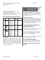
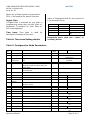
FLOW INDICATOR TOTALISER MODEL: 1008S
masibus
Doc Ref No: m18A/om/101
FLOW INDICATOR TOTALISER MODEL: 1008S
Issue No: 04
masibus
Ref. No:
Issue No: 01
User’s Manual
FLOW INDICATOR TOTALISER 1008S
Masibus Automation And Instrumentation Pvt. Ltd.
B/30, GIDC Electronics Estate,
Sector-25, Gandhinagar-382044, Gujarat, India.
Ph: 91 79 23287275 -79
Fax: 91 79 23287281, 82
Email: [email protected]
Web: www.masibus.com
masibus
FLOW INDICATOR TOTALISER MODEL 1008S
Ref No: m18A/om/101
Issue No: 04
Contents
(1) INTRODUCTION
(1.1) TECHNICAL DETAILS
(2) SPECIFICATIONS
Tables
TABLE 1 SPECIFICATIONS
TABLE 2 CONNECTION DETAILS
(3) HARDWARE DESCRIPTION
(3.1)
(3.2)
(3.3)
(3.4)
(3.5)
CPU CARD
KB / DISPLAY CARD AND FRONT PANEL
ENCLOSURE
POWER SUPPLY
RELAY CARD
(4) INSTALLATION GUIDE
TABLE 3
KEYBOARD DETAILS
TABLE 4
RUN MODE PARAMETER DETAILS
TABLE 5
PROGRAM MODE PARAMETER
DETAILS
TABLE 6 TIME BASE SETTING DETAILS
TABLE 7 CONFIGURATION MODE PARAMETERS
(5) OPERATING DETAILS
(5.1) DISPLAY
(5.2) KEYBOARD
(5.3) RUN MODE
(5.4) EDIT MODE
(5.5) PARAMETER DESCRIPTION
(5.5.1) Program MODE
(5.5.2) Configuration MODE
(5.5.3) Calibration MODE
TABLE 8 FIVE POINT LINEARISATION
TABLE 9 CALIBRATION MODE PARAMETERS
DETAILS
TABLE 10 MODBUS REGISTERS DETAILS
(6) CALIBRATION PROCEDURE
(7) START AND STOP KEY FUNCTIONS
(8) MODBUS PROTOCOL
(9) ORDERING CODE
Operator’s Manual
Page 1 of 19
masibus
FLOW INDICATOR TOTALISER MODEL 1008S
Ref No: m18A/om/101
Issue No: 04
1. INTRODUCTION
This is a microcontroller based Indicator Totaliser unit, with very high performance
to price ratio. It is highly versatile, accurate
and different from the conventional
indicators.
1.1 TECHNICAL DETAILS:
• x 110
The instrument is made in 96 x 96
mm size with DIN standard panel cutout of
92 x 92 mm.
Front is sealed membrane type to
withstand dusty environment. On back
plate detachable terminals are provided for
easy connection.
The programming, calibration and operation
of the instrument are by four simple keys
and with two independent displays groups:
one for flow rate and one for batch total.
Operation of the instrument is menu driven
with user understandable prompts. For
protecting programmed data password
protection facility is provided. Integrated
total, batch total and roll count are cleared
by special password.
2.1 Measured input signal:
Number of Inputs: 1(one) with
Optional 2 & 3
• Input Type, Measurement Range
& accuracy: As per table 1
• Sampling Period: 15sps
Burn out detection: Available 1 to
5VDC, 4 to 20 mA, 0 to 10 KHz.
• Input Resistance:
250 Ohms Internal for current Input
320K Ohms for Voltage Input
• Allowable
signal
source
resistance: DC input voltage: 1KΩ
or less . Effect from allowable signal
source Resistance: 0.031 % / 100
Ω
or less
• Range :(Table-1)
Note: Input type is factory set.
•
INPUT TYPE
DC
Voltage
DC
Current
The product is made to accept current (420 mA, 0-20mA), Voltage (1-5Volt, 0-5
Volt) input, pulse input & Digital input. It is
available as a single input version only. The
instrument is providing with the five-point
calibration. The unit can be calibrated in
installed condition itself by front panel keys
at predefine points.
The set Parameters and integrated total are
stored in serial NVRAM. No battery back up
is required.
*Pulse
input
0 to
20000
± 0.25%
of full
scale ± 1
Count
099999999
**0.45 %
0-5V
4 to
20
mA
0 to
20
mA
0 to
10
Khz
*
Max. Pulse level<=24V
Min. pulse level > 1.0V
** ±(0.45% of Reading + 1 Digit)
•
Operator’s Manual
Accuracy
1-5V
Integrated /
Batch total.
•
2. SPECIFICATIONS
RANGE
•
Allowable input Voltage:
voltage: ±20V DC
Noise Rejection Ratio:
Common Mode: > 100db
Normal mode: > 40db
Response time:
Page 2 of 19
DC
masibus
FLOW INDICATOR TOTALISER MODEL 1008S
Ref No: m18A/om/101
Issue No: 04
Input to relay o/p: < 1 second.
Input to Analog o/p: < 1
second or less, 63 % ( 10 - 90%)
maximum excursion when PV changes from
10% to 90%)
• Resolution: 16 bits
• Polarity Protection: Not Provided
.
2.2 Loop Power Supply:
24VDC ± 5% @ 50mA
2.3 Calibration:
•
Ambient, Zero and span adjusted by
digital calibration through front panel
Keys. One shot calibration of both
input and output.
2.4 Retransmission Output:
•
•
•
•
•
Number of output points: 1
Output Signal: 4 to 20 mA DC
On load resistance: 500Ω or less
Output accuracy: ± 0.25% of full
scale +1 count
Resolution: 12 bits (5µA)
2.5 Contact Input (Digital input):
•
•
•
•
•
Usage:
Input 1: Stop batch
Input 2: Integration total zero
(Therefore Batch total & roll count
will be zero)
Input 3: Start batch
Input 4: Batch total zero
Number of Inputs: 4
Input type: Non- voltage contact
input or transistor open collector
input
Input contact capacity:
12AVDC,10mA or more
(for non – voltage contact input)
On/ Off determination:
For non-voltage contact input
ON = contact resistance of 1KΩ or
less,
OFF = contact resistance of 20KΩ or
more
Operator’s Manual
(Time required for o/p to reach 63% of the
•
•
For transistor contact input
ON = 2V or less
OFF = leak current of 100µA or less
Minimum retention time for
status detection: About 1 Second
2.6 Contact Output:
•
•
•
•
Usage: Flow alarm & batch
Number of relay contact outputs:
4 (2 Flow alarm relays, 2 Batch
relays)
Relay contact rating:
250VAC/5Amps
Relay contact terminal: 3
(NO, NC, Common)
2.7 Display Unit Specification:
•
•
•
•
Process Value display: 0.56” 5
digit 7- segment red display
Integrated total display: 0.40” 8
digit 7- segment red display
Parameter display: Same
integrated total display
Status indicating lamp: Red LED’s
2.8 Construction/Installation/
Wiring:
•
•
•
•
•
•
•
•
•
Structure:
Front fascia IP54 complied (not
certified), Enclosure GP (IP20).
Body construction:
Polycarbonate plastic.
Case color: Dark grey
Weight: 0.45Kg
Dimension: 96 W* 96H*125D max
behind panel with terminal (all in
mm)
Mounting: Panel mounting
Panel cut-out:
92W* 92H (all in mm)
Wiring: 2.5sq.mm
Standard Accessories:
2 mounting clamp
2.9 Power supply/Isolation
Page 3 of 19
masibus
FLOW INDICATOR TOTALISER MODEL 1008S
Ref No: m18A/om/101
Issue No: 04
•
•
•
Power supply: 90 to 255VAC, 50Hz
(Optional 24VDC)
Power consumption: <10VA
Memory backup: EEPROM
Withstanding voltage:
Between primary terminal and
secondary terminal 1500VAC
for 1minute.
Between primary terminal and
ground terminal 500VDC for
1minute.
Between ground terminal and
Secondary terminal 500V AC for 1
minute.
(Primary terminal: Power supply,
relay output)
(Secondary terminal: Analog
input/output signal terminals,
contact input terminal)
• Isolation resistance:
Between power supply terminal and
ground terminal, 500VDC, 50MΩ.
• Isolation Specification:
Measured input terminal: Isolated
from other input/output terminals.
Not isolated from 24Vdc supply
(Transmitter power supply) and
internal circuit.
RS-485 communication terminal:
Isolated from other input/output
terminals and internal circuit.
Power supply terminal: Isolated
from other input / output terminals
and internal circuit.
•
24V dc supply for Transmitter:
Not isolated from the measured
input terminal & internal circuit,
isolated from other input/output
terminals.
Retransmission output terminal:
Isolated from other input/output
terminals and internal circuit.
Ground terminal: Isolated from
other input/ output terminals and
internal circuit.
2.10 Environmental conditions
•
•
•
FUNCTIONAL SPECIFICATIONS
2.11 Alarm Function
•
•
•
Contact input terminal: Isolated
from other input/output terminals
and internal circuit.
Relay Contact o/p terminal
(Digital input): Isolated from other
input /output terminals and internal
circuit.
Operator’s Manual
Normal Operating conditions:
Ambient Temperature: 0 to 55°C
Ambient humidity: 30 to 90% RH
(non-condensing)
Warm up time: >10 Minute
Transit/storage conditions:
Temperature: 0 to 70°C
Humidity: 30 to 90 % RH (nonCondensing)
Effect of operating conditions:
Effect of ambient temperature:
For voltage input:
± 0.005% of FS/ °C or less
For analog output:
± 0.010% of FS/ °C or less
Alarm types: Flow high limit, Flow
low limit,
Batching Alarm: Pre warn and set
point.
Setting Ranges for Process Value
Alarms:
Flow (PV) Alarms:
Min = Zero of individual I/P type
mentioned in table1
Max = Span of individual I/P type
mentioned in table1
2.12 Display and Operation function
•
PV display: 5 digit red 7 segment
display for flow rate
Page 4 of 19
masibus
FLOW INDICATOR TOTALISER MODEL 1008S
Ref No: m18A/om/101
Issue No: 04
•
•
•
•
Integrated total: 8 digit red 7
segment display for integrated total
Parameter display: Same 8 digit
red 7 segment display integrated
total
Status display: Red LEDs (for alarm
& Batch)
Operation keys:
◄ /Start: to enter in to sub menu,
select digit, start batch.
▲/stop: Increment value of selected
digit, stop batch.
(Set or Index) to enter in to
configuration mode, calibration
mode, program mode, scroll menu
and save edited data.
2.13 Communication
•
•
•
•
•
•
•
•
Protocol: Modbus RTU serial
Standard: EIA RS-485
Max. Communication distance: ≤
1200 mtrs. (For 9600 bps RS 485)
Communication method: 2 wire
half duplex (RS 485)
Data frame: N, 8, 1
Communication rate:
9600, 19200 bps
Max. Connectable
controllers/Indicator: 32
Address range: 1 to 99
2.14 Special function
•
•
•
•
•
•
•
Square root extraction: Applicable
Digital filter: Applicable
Time base unit:
Second, minute, hour, day
Conversion factor: 0.00 to 99.99
Five point linearization: Applicable
Pulse out put:
Maximum pulse: 20 pulses/Sec.
Excitation Voltage: <24Vdc with
maximum 10 mAdc
Low flow cut off: Applicable
3. HARDWARE DESCRIPTION
Operator’s Manual
The unit consists of a CPU, KB/Display card
and Power Supply (SMPS)
3.1 CPU CARD:
The CPU card has necessary hardware for:
-Driving Thirteen(8+5) digit multiplexed
Display
-Four key keypad interface.
-Watch dog circuit.
-ADS1110 circuit interface for input.
-DAC7571 circuit for current output.
The CPU card carries 5-pin & 4 pin,
5.08mm pitch and detachable Male
connectors.
The connector is accessible from back panel
cutout.
Matching female connectors are supplied
along with the instrument.
The card is connected with KB/Display card
and it is fitted with front & back plate.
3.2 KB / DISPLAY CARD AND
FRONT PANEL:
A KB / Display card has two set of displays:
5-digit display for rate indication. (First
group of displays)
8-digit display for totaliser. (Second group
of displays)
Four keys are also mounted on this card.
The card is connected with CPU card with
20-pin connector. The card is fitted with the
bezel. An overlay is provided on the front
side.
3.3 ENCLOSURE:
This is general purpose DIN standard
Polycarbonate Plastic enclosure suitable for
panel mounting. Panel mounting is to be
done using side brackets.
3.4 POWER SUPPLY:
This is a Switch mode power supply. It
accepts mains input ranging from 90-255
VAC.
Page 5 of 19
masibus
FLOW INDICATOR TOTALISER MODEL 1008S
Ref No: m18A/om/101
Issue No: 04
It generates DC supply required for Logic &
signal conditioning. It also generates
+24VDC for transmitter.
The SMPS card carries a 3-pin, a 5 pin and
a 2 pin, 5.08 mm pitch, detachable Male
connectors.
The connectors are accessible from back
panel cutout.
Matching female connectors are supplied
along with the instrument.
• Ensure that the instrument is properly
earthed.
• Check voltage between earth and neutral
terminal. It should be less than 2 volts
AC. If this voltage is greater then it
results in unstable reading. In such a case
use ISOLATION TRANSFORMER to provide
mains to the instrument.
Table 2: Connection Details
N
o.
Detail
3.5 RELAY CARD:
1
2
3
Line
Neutral
Earth
The Relay card carries a 12-pin, 5.08 mm
pitch, and detachable Male connector.
4
5
6
7
8
9
10
DIN1+
DIN2+
DIN3+
DIN4+
DINPOUT+
POUT-
11
C1
12
13
14
15
16
NO1
NC1
C2
NO2
NC2
A Relay Card is connected between CPU
card and SMPS card. It consists of 4
OMRON 12V DC relays mounted with the
help of side PCBs.
The connectors are accessible from back
panel cutout.
Matching female connectors are supplied
along with the instrument.
4. INSTALLATION GUIDE
Following steps should be followed for
proper installation of the instrument.
• Unpack the instrument from the packing
box carefully
• Mount the instrument in the panel cutout
of 92mm x 92mm.
• Fix the instrument with the panel using
two side brackets.
• All the electrical connections to be done at
back panel on screw type terminals.
• Refer the Appendix for back panel
connection.
• Make sure that no wire is connected
loosely to avoid generation of spark and
RFI. Before connecting the mains, check
the mains configuration on the back
panel.
Operator’s Manual
MAINS
95-255
VAC
Digital
Inputs
Pulse
o/p
Low
Alarm
Relay
High
Alarm
Relay
No.
Detail
17
18
19
C3
NO3
NC3
WP
Relay
20
21
22
23
24
25
26
C4
NO4
NC4
RxTx+
RxTxOUT+
OUT-
EP
Relay
27
24VDC 4-20mA,
(GND)
0-20mA
0-5v, 1-5v
I/P1+
I/P1Pulse I/p (0-10KHz)
24V DC (50mA)
28
29
30
31
Serial I/F
RS 485
Retxn O/p
4-20mA
5. OPERATING DETAILS
The following paragraphs give detailed
description of how to operate the unit.
Before using the instrument, make sure to
study and understand this section.
5.1 DISPLAY:
The unit has two windows/groups of
display:
Upper:
Five digits 7-segment, 0.56” Red LED
display:
It displays Flow rate/Process variable.
Page 6 of 19
masibus
FLOW INDICATOR TOTALISER MODEL 1008S
Ref No: m18A/om/101
Issue No: 04
Lower:
Eight digits 7-segment 0.40” Red LED
display:
In normal mode of operation, Batch
total/Integration Total is displayed. While in
EDIT mode, parameters are displayed in
this window.
• Engineering value proportional to the
input signal will be displayed as Process
variable. Decimal point is displayed at
selected position.
• Last saved batch total/integration total
will be displayed on the lower window.
5.2 KEYBOARD:
Unit has 4 key membrane keypad
organized as 4 x 1 matrix.
Following Table explain the Operation of the
Keys used for configuration.
Table 3 Keyboard Details
Key
SET
(Index)
(Decr)
(Incr)
ESC
(Cancel)
Function
1.It will allow user to enter in EDIT
mode, when instrument is in RUN
mode.
2. It will scroll menu and submenu
when it is enabled
3. It will save edited data.
1. It will enter into the submenu,
when main menu is enabled and
shows submenu’s value.
2. It will select the digit to modify,
when value is edited.
3. It will start batch, if pressed, when
IT & BT are being displayed
1. It will increment value of digit
selected or constant selected.
2. It will stop batch, if pressed,
when BT/IT are being displayed.
It will escape to previous status, with
reference to its current status.
Sequence of status:
IT
MENU
SUB-MENU
Parameter’s Value
Escape sequence
When Esc key is pressed in Menu, the
instrument will come in RUN Mode. If
user wants to go in EDIT mode, he
will have to enter the correct
password again.
5.3 RUN MODE:
Whenever mains is switched on to the unit,
5.4 EDIT MODE:
In this mode user can verify or modify,
various parameters.
To enter the EDIT mode, correct password
is to be entered.
Password Protection:
When INDEX key is pressed, following
prompt will be displayed at lower panel 7segment display.
“bAt tot” , then
“Int tot” , then
“roL Cnt “ , then
“PASSUord” .
User Can select the Parameter –any of the
above prompt to display corresponding
value by pressing INDEX key and then
pressing “START KEY”(It is digit select key
for editing the parameters),
At the selection of password, value “0000”
is displayed.
Enter the correct password value with the
help of START (digit select key) and STOP
key (Incr key) and press INDEX KEY
(INDEX key is used as ENTER key)
If correct password is entered & INDEX key
is pressed, it will show the first mode PROG
MOD. If wrong password is entered, then
“0000” MSG will be displayed again at
lower display window.
5.5 PARAMETER DESCRIPTION:
There are total three Menu Items:
Operator’s Manual
Page 7 of 19
masibus
FLOW INDICATOR TOTALISER MODEL 1008S
Ref No: m18A/om/101
Issue No: 04
1.
2.
3.
Three parameters are displayed after
entering correct password.
These parameters related with totaliser are
mentioned in the following table.
Table 4:Run Mode parameters Details
No.
Name
Description
1
Batch
Total
This parameter
displays the
Total flow since
batch is
started (‘BT’)
2
Integra
ted
Total
3
Roll
Count
This parameter
displays the
Total flow since
Last Reset.
(‘IT’)
This parameter
displays the
roll over count
of the
Integrated
Total from
‘99999999’ to
‘0’ (‘Rc’)
This is an eight digit totalized value,
displayed as integrated total. As per the
selected time base, Zero and Full-scale
settings, this total is updated continuously,
proportional to input.
Rollover Count (RC):
This is a two-digit value, displayed as the
rollover that takes place when integrated
total gets higher than higher limit. When
the integrated total crosses high limit, this
count is incremented by one.
Max
digits
Max. 8
Limits
Max. 8
099999999
So the total integration will be equal to
(Rollover Count) x (hi limit + 1) +
Integrated Total (It)
Max. 4
0 - 9999
Integrated total, batch total and roll count
are cleared by special password.
099999999
Batch total:
This is an eight digit totalized value,
displayed as Batch total. As per the
selected time base, Zero and Full-scale
settings, this total is updated continuously,
proportional to input. When New Batch
Starts or Integration total is reset this value
also gets initialized to 0.
Operator’s Manual
Integrat
ion
total:
Program Mode
Configuration Mode
Calibration Mode
On power fail detection, current value of
Batch total, integrated total and rollover
count are stored in NVRAM.
Following section will describe the different
Item of individual submenu.
5.5.1 Programme mode:
Programming menu provides facility to
configure the relay for different function.
Table 5: Program Mode parameters
Details
Page 8 of 19
masibus
FLOW INDICATOR TOTALISER MODEL 1008S
Ref No: m18A/om/101
Issue No: 04
Low alarm and high alarm:
Value of Low alarm should be lower than
that of high alarm. If user tries to set value
of Low alarm greater than high alarm
Value, error message will be displayed.
Similarly, if user set value of High alarm
lower than low alarm Value, error message
will be displayed. Alarms value cannot be
set greater than Full-scale Value (FS).
Comparison with Zero and full-scale:
Low Alarm value should be greater then
Zero value. If user tries to set value of Low
alarm less than Zero Value, error message
will be displayed.
If (Low Alarm< Zero value), “error”
message appears.
If ‘Batch Mode’ is selected to ‘Normal’, then
two parameters will not be displayed.
Input Type:
Based on requirement, user can select
input type. It will be either Voltage or
Current or Pulse.
Instrument Type:
If “instrument type” is set as indicator, then
Prewarn and Setpoint parameter will not
be displayed in Program mode.
Square root:
If user selects this mode as ‘yes’, flow rate
will calculated using square root algorithm.
Alternatively linear calculation will be done.
Digital Input:
High-Alarm value should be greater then
Full-scale value. . If user tries to set value
of High-alarm greater than Full-scale value,
error message will be displayed.
No
.
1
Name
Description
High Alarm
2
Low Alarm
Alarm
conditions
for flow rate.
If (High Alarm > full-scale value),
“error” message appears.
3
Set point and prewarn:
Error message will be displayed if, set point
value is lower than pre-warn and vice
versa.
5
Pre warn
Alarm
Set Point
Alarm
Lo Alrm
Rly
6
Hi Alrm Rly
7
Prewarn
Rly
Set Pnt Rly
Alarm ON-OFF :(submenu no 5 to 8):
Using these settings, user can set
alarm/relay availability. If particular relay is
set as ‘yes’, that particular alarm indication
will be present over the display card and
relay action will come into effect.
5.5.2 Configuration mode:
Batch Mode:
If ‘Batch Mode’ (Batch nod) is selected to
‘Counter’, then two parameters “Batch
count”(Bat cnt) and “No of Batches”
(No_of_bh)
will
be
displayed
in
Configuration mode.
Operator’s Manual
4
8
9
Filter
number
No of
digit
5
Lo
limit
0
5
0
Batch control
values.
6
0
6
0
Low alarm
relay
-
Yes/No
High alarm
Relay
Prewarn
Relay
Set Point
Relay
-
Yes/No
-
Yes/No
-
Yes/No
2
1
Hi
limit
2000
0
2000
0
9999
99
9999
99
25
If Digital input is selected as ‘yes’ than only
digital inputs will work. Four digital inputs
are there.
DIN1+: Stop Function
DIN2+: Integration (Int tot) Zero (since IT
is initialize to 0, therefore batch total/roll
count are also initialized to 0)
DIN3+: Start Function
DIN4+: Batch total (bat tot) Zero
DIN-: GND (12V GND)
Page 9 of 19
masibus
FLOW INDICATOR TOTALISER MODEL 1008S
Ref No: m18A/om/101
Issue No: 04
When any of these inputs is connected to
DIN-, it will perform its specific function.
Digital Filter:
If Digital filter is selected as ‘yes’ than in
programming mode user can see ‘filter no’
parameter. If selected ‘no’ then ’filter no’
will no be displayed.
Time base: Time base is used
calculation & display of flow rate.
Value of Integrated total for time period of
t (in seconds) will be
for
Table 6: Time base Setting details
Select
0
Time base
Second
Divisor
1
1
2
Minute
Hour
60
3600
3
Day
86400 (24 x 60 x
60)
(1 x 60)
(60 x 60)
Integration total= (flow rate * time’t" in
seconds)/divisor
Table 7: Configuration Mode Parameters
Sr.
No.
1
2
Name
Description
Batch Mode
Input Type
Type Of Mode, For Flow Control
Type Of Input
4
5
Type Of
Instrument
Square Root
Digital Input
6
Digital Filter
7
Time Base
Type Of Instrument, Which You Want To
Use.
Mode Of Linearization
To Be Used To Reset Batch Total,
Integration total & to start batch and
tostop batch
If Yes Than In Programming Mode It Will
Show Filter No.
For Calculation/Display Of Flow Rate
3
8
9
10
11
ZR1
FS1
No Of
Batches
Batch Count
12
13
14
15
16
Relay Mode
Cut Off
DP
SF1
FL1
17
18
No Of
Digit
-
Hi Limit
Normal, Counter
0-5v, 1-5v, 0-20ma, 420ma,Pulse
Indicator/
Totaliser
Yes/No
Yes/No
-
Yes/No
-
Sec, Min, Hour, Day
Zero Value
Full Scale Value
5
5
2
00000
00000
00
20000
20000
99
Counter Will Count How Much Batches
Has Been Taken
Two Type Of Mode
2
00
99
Decimal Point
Full Scale For Segment 1
% Age Of Full Scale (Segment 1)
3
6
-
SF2
FL2
Full Scale For Segment 2
% Age Of Full Scale (Segment 2)
6
-
19
20
SF3
FL3
Full Scale For Segment 3
% Age Of Full Scale (Segment 3)
6
-
21
22
SF4
FL4
Full Scale For Segment 4
% Age Of Full Scale (Segment 4)
6
-
Operator’s Manual
Lo Limit
Normal, Failsafe
100
0,0.1,0.01,0.001
00000
20000
10,20,30,40,50,60,70,80,90,1
00
00000
20000
10,20,30,40,50,60,70,80,90,1
00
00000
20000
10,20,30,40,50,60,70,80,90,1
00
00000
20000
10,20,30,40,50,60,70,80,90,1
00
000
Page 10 of 19
masibus
FLOW INDICATOR TOTALISER MODEL 1008S
Ref No: m18A/om/101
Issue No: 04
23
24
25
26
27
28
Baud Rate
Serial No
Pout
Default Display
2
4
-
29
30
Pass
Conversion
Factor
Clear
Total
4
4
00000
20000
10,20,30,40,50,60,70,80,90,1
00
9600,19200
01 TO 99
0001 TO 9999
Batch Total/Integration Total
(Bat Tot/Int Tot)
0000-9999
00.00-99.99
4
“PASS” & 0000-9999
31
SF5
FL5
Full Scale For Segment 5
% Age Of Full Scale (Segment 5)
To Clear Integration /Batch Total And
Roll Count
Batch counter and no of batches:
These parameters will be displayed only if
the’Batchmode’ is selected to Counter type.
No of batches: Set the parameter according
to the requirement. It decides how much
batches are to be taken
Batch counter: It will be incremented by 1
whenever a new batch is started by START
key in run mode. When batch
counter value becomes equals to ‘no of
batches’ value, then it will not start new
batch.
Note: To reset batch counter, Enter in
batch count (bat cnt) parameter in
configuration mode. Press “Start” key to
see its value. Now if user presses “Stop”
key Batch counter value will be cleared to
0.
Relay-mode:
In ‘Relay-mode’ (relay nod), if set to
‘normal ‘mode then alarm relays and LEDs
will work according to alarm values.
i.e. Relays on, LEDs on
Relays off, LEDs off
But if set to ‘Failsafe’ Mode then alarm
relays and LEDs will operate reversibly.
i.e. Relays on, LEDs off
Relays off, LEDs on
Cut off: (Low flow cut-off)
Operator’s Manual
6
-
Cut off could be set to 0000 to 0100.
Cut off will display the % value.
Cutoff value = Cutoff parameter (in %)*Full
scale value
If full scale value is 10000 and cut off is 5%
Then cut off value will be calculated as
= (5/100)*10000 = 500.
So, if the displayed flow rate (displayed at
upper window) is less then 500, it will not
be added in integration.
Decimal Point Selection:
Decimal point selection will be given from
the configuration mode.
Select
0
0.1
0.01
0.001
Decimal position
No decimal
One decimal
Two decimals
Three decimals
Five point Linearization:
This instrument has feature of five-point
linearization. User can define up-to five
different segments of the full-scale input (in
percentage) with Full-scale engineering
value for each segment. We have to
program the value of flow rate at different
inputs.
Here we are defining five scale factors for
the current input 4 mA to 20mA. Let’s have
one example to understand this concept.
Page 11 of 19
masibus
FLOW INDICATOR TOTALISER MODEL 1008S
Ref No: m18A/om/101
Issue No: 04
For Example:
ZR = 00000 and FS = 10000, Let us
assume the Unit is current input mode.
Table 8 Five Point Linearization
In above example
Flow rate on Display varies between:
• 0 – 2000 for input of 0 % – 10%
• 2000 – 4000 for input of 10% – 50%
• 4000 – 4500 for input of 50 % – 60%
• 4500 – 7500for input of 60 % – 80%
• 7500– 10000 for input of 80 % – 100%
If user wants a flow to be linear through
out the span than configure this parameter
as: SF1 = FS1, FL1 = 100 %.
User is not required to initialize SF2, SF3,
SF4, SF5, FL2, FL3, FL4 and FL5.
Pout Selection:
Pout value decides the pulse Output.
There will be a pulse at pulse output pins
(PIN NO.9, PIN NO 10), whenever a
integrated total value is greater than by
POUT by previous IT value [where last
pulse is registered], it will be added to the
integration total value.
i.e.
Current IT value ≥ (Pout + previous IT
value).
Example:
1. If Flow rate = 1000, Pout = 1000,
Time base = second,
Every second, 1000 is added in integration
total. Since pout is 1000, 1 times of pout
value is added to integration-total every
sec. Therefore we will have 1 pulse/sec.
2. Flow rate = 1000, Pout = 100,
Time base = second,
Every second, 1000 is added in integration
total. Since pout is 100, 10 times of pout
value is added to integration-total every
Operator’s Manual
sec. Therefore we will have 10pulses/sec. It
could not be observed on CRO. For this use
a pulse counters for testing.
3. Flow rate = 600, Pout = 10,
No
.
Flow
rate
Value
Parame
ter
Display
Value
1
2
FL1
FL2
10%
50%
SF1
SF2
2000
4000
Input
Current
mA
5.6
12.0
3
4
5
FL3
FL4
FL5
60%
80%
100%
SF3
SF4
SF5
4500
7500
10000
13.6
16.6
20
Time base = min,
Every second, 10(600/60) is added in
integration total. Since pout is 10, 1 times
of pout value is added to integration-total
every sec. Therefore we will have
1pulse/sec or 60 pulses/min.
4. Flow rate = 600, Pout = 100,
Time base = min,
Every second, 10(600/60) is added in
integration total. Since pout is 100, 1/10
times of pout value is added to integrationtotal every sec. Therefore we will have 1
pulse/10 sec or 6 pulses/min.
Default Display: This parameter will select
the parameter to be displayed in run mode.
If Int tot / Bat tot is selected then in run
mode ‘Integration total ‘/ ‘Batch total ‘will
be displayed on lower panel accordingly.
If “instrument type” parameter is set as
indicator, then this parameter will not be
displayed in Configuration mode and
Integration total will be displayed in run
mode.
Password: A ‘PASS’ parameter is added in
configuration mode.
But it will always show ‘0000’.User has to
remember the password.
If user needs to change password, then go
in ‘pass’ parameter, enter the required
password and press Enter key.
Page 12 of 19
FLOW INDICATOR TOTALISER MODEL 1008S
Ref No: m18A/om/101
Issue No: 04
For eg: If user enters ‘1234’ in ‘pass’
parameter, then, to enter in EDIT mode, a
password ‘1234’is to be entered.
Conversion Factor (Conv-F):
It is a constant, which simply divides
process value by the factor set. Usually, it
is set as 1.00
For example, if process value is 100
liters/minute & conversion factor is 1 then
it will simply integrate process value as it
is.
If we change conversion factor = 2, then it
will divide process value by that factor i.e.
100/2 = 50 & it integrates that value (in
No
Setting
Description
1
Cal
Zero
Cal
Span
Out
Zero
Zero Cal.
Count
Span Cal.
Count
Zero Cal.
Count for
Output
Span Cal
Count for
Output
If user selects
‘yes’, then
Outzero =
800 and Out
span (4000)
is selected.
2
3
4
Out
Span
5
Default
Out
No
of
digit
4
Lo
limit
Hi
limit
5
4
000
0
4095
5
000
0
4095
Yes/No
both integral and batch total) but on the
display it shows original process value.
Clear total:
Parameter to reset IT, BT, and RC.
If user enters the correct password, IT, BT
and Roll over count gets cleared (initialized
to Zero). And ‘cleared’ message is
displayed on the lower window of display.
By pressing ESC key, menu goes back to
the clear total. If wrong password is
entered, ‘cleared’ message will not appear.
5.5.3 Calibration mode:
Operator’s Manual
masibus
Table 9: Calibration Mode Parameters
Details
This menu allows user to perform
calibration of analog input & output.
INDICATION:
For conversion in engineering value, the
input is scaled between Zero and Full scale
set values as per following formula (for
linear mode):
For any type of input:
Indication (Engineering Value)
X
=
+ Zero
(CALS-CALZ)
X = (Input signal - CALZ) * (Full scale Zero)
CALZ = Value of input applied during zero
calibration
CALS = Value of input applied during Span
calibration
If input signal is outside the set Zero and
Full-scale limit, all the four digits of the
Process variable starts flashing. Only when
input signal comes back into the allowed
range, display becomes steady.
NOTE:
1). When no input is connected to the unit,
it will display “open” message in pulse
mode, current mode and voltage mode.
(Pulse input 0 to 10Khz, 4-20mA, 1-5V)
2). When input is out of the range the
display will blink.
6. Calibration Procedure:
Input Calibration:
As explained earlier, One can do calibration
thro' the keyboard itself, Zero and Fullscale values are stored in NVRAM.
Page 13 of 19
masibus
FLOW INDICATOR TOTALISER MODEL 1008S
Ref No: m18A/om/101
Issue No: 04
1. Switch on the instrument and allow
15 minutes of warm up time before
starting calibration.
2. Take a standard source. Set it’s
output at desired Zero value. Apply
output of the source to the input
terminals of connector pin according
to input select.
3. In calibration mode, Press shift /start
key to calibrate zero. This will show
prompt - “CAL Zr1”. To enter in
“CAL Zr1” mode press shift /start key
4. Lower window displays a count. This
is raw count proportional to analog
input. Wait till counts are stable,
save this count by pressing ‘Index’
key twice.
5. Press ESC key to come out from
“CAL Zr1”.
6. Now apply input equal to Full
scale/Span (CALS):
7. Set output of the source at desired
full-scale value. Apply output of the
source to the input terminals
8. Press index key to go to calibration
span. This will show prompt -”CAL
SPn1”. To enter in “CAL SPn1” mode
press shift /start key.
9. Lower window displays raw counts
count proportional to analog input.
10.Allow the reading to settle and Press
‘Index’ Key twice to save the count.
11.This reading will be stored as Span
Now the instrument is calibrated.
12.Press ESC key to come out from
“CAL SPn1”.
Output Calibration:
For
output
calibration,
measuring
instrument should be at least 3 times
accurate.
Out zero and Out span:
These two parameter are used for the
calibration of re-transmission output. Users
have to change the value of out zero and
out span for the zero setting (for 4mA) and
Operator’s Manual
span setting (20 mA) respectively for retransmission out put.
13. In calibration mode, go to out zero
calibration mode by pressing index
key. This will show “oUT ZEro”
prompt. To enter in
“oUT ZEro”
mode press shift /start key
14. Lower window displays a count.
Using shift /start or inc/stop key to
set
reading
(zero
output)
of
connected ampere meter at output,
exactly at 4.000mA and press index
key to store the calibration value.
15.Press ESC key to come out from
“oUT Zero”.
16.Press index key to go to out span
calibration. This will show prompt“oUT SPAn”. To enter in “oUT SPAn”
mode press shift /start key
17. Lower window displays a count.
Using shift /start or inc/stop key to
set
reading
(span
output)
of
connected ampere meter at output,
exactly at 20.000mA and press index
key to store the calibration value.
18.Press ESC key to come out from
“oUT SPan”.
19.This reading will be stored. Now the
instrument is calibrated.
If user enters values greater than 4095
“error” message will appear.
It user enters out zero value > out span
value then also “error” message will
appear.
Accuracy of retransmission O/p 0.25% of Full span.
7. Start & Stop function:(In
Run Mode)
START key:
If this key pressed batching relays (WP/EP)
gets ON & BATCH TOTAL = 0.It means a
new batch is started. If START key is
Page 14 of 19
FLOW INDICATOR TOTALISER MODEL 1008S
Ref No: m18A/om/101
Issue No: 04
pressed again and again, it will not start
the batch until WP/EP relays gets OFF .
Relays get OFF by two ways:
1. STOP key
2. BATCH TOTAL crosses the value of
SETPOINT.
STOP key:
If user presses STOP key in running batch,
batching relays (WP/EP) gets off. If again
STOP key is pressed again and again only
batching relays gets ON/OFF (only if BATCH
TOTAL < (WP/EP) values. No new batch will
be started by STOP key. When batch total
value crosses the WP/EP value, relays gets
OFF and batch is over.
Again if START key is pressed then a new batch
will start making BATCH TOTAL = 0. Batching
relays gets ON.
8. MODBUS protocol
Here we will Two-function code:
Function code:
03h: for reading analog parameter value.
06h: for writing analog parameter value.
01h: for reading digital parameter value.
05h: for writing digital parameter value.
Command message consist of 4 fields as
shown below.
Command message.
Station no
Function code +80H
Error code
Error check (crc-16)
Here master will send command to the
slave and slave will response to the master
if its unit no. Matches with command
message’s station no. Field.
To a relevant message, slave station
creates and sends back a response
Operator’s Manual
masibus
message, which corresponds
command message.
to
the
If the content of the command message
have any abnormality (for example, non
actual function code is designated) other
than transmission error, slave does not
execute that command but creates and
sends back a response at error detection.
The composition of error message at error
detection is shown below.
Error message:
Station no (1 byte).
Function code (1 byte)
Data (4 byte)
Crc (2 byte)
Error code:
01H: illegal function
02H: illegal data address
03H: illegal data value.
08H: crc error.
Here slave will first check crc, if crc is o.k.
it will assume that there is no transmission
error. And if crc is not matched with crc
calculated by slave station, slave station
will send back error message with error
code 08H. After crc slave will check unit no.
If it matches with its own unit no, it will go
ahead with command. Otherwise it will
neglect the command.
Note:
For Analog Read:
FLx (FL1, FL2, FL3, FL4, and FL5) consists
of 9 selectable values from 10 to 100.
For 10 it will read…. 0
For 20 it will read…. 1
If FL1 =100, Hex address 0x0024 will show
9.
For Digital Read/Write: Cmd Action = 1;
Reg. Address = 0x0001 to 0x0004.
Page 15 of 19
masibus
FLOW INDICATOR TOTALISER MODEL 1008S
Ref No: m18A/om/101
Issue No: 04
1. Relays will read 0- OFF (relay) 1 – ON
2. For start /stop function
Cmd Action = 5
Reg Address = 0x0005
For Start – write 1
For Stop – write 0
Table 10 Modbus Registers Details
Sr.No.
Reg.No.
Parameter Name
1
40001
High alarm
Length in
bytes
(Words)
2(1)
Read/Write
2
40002
Low alarm
2(1)
R/W
3
40003
Setpoint
2(1)
R/W
4
40004
Setpoint+2
2(1)
R/W
5
40005
Prewarn
2(1)
R/W
6
40006
Prewarn+2
2(1)
R/W
7
40007
Conv-Factor
2(1)
R/W (00.00-99.99)
8
40008
Filter no
2(1)
R/W (1 to 25)
9
40009
Batch mode
2(1)
R/W (0 for Normal, 1 for Counter)
10
40010
Type of input
2(1)
R/W (0 for 0-5V, 1 for 1-5V,
2 for 0-20mA, 3 for 4-20mA,
4 for pulse)
11
40011
Type of Inst
2(1)
R/W (0 for indicator, 1 for Totalizer)
12
40012
Sqrt mode
2(1)
R/W (0 for Yes, 1 for No)
R/W
13
40013
Digital input
2(1)
R/W (0 for Yes, 1 for No)
14
40014
Digital filter
2(1)
R/W (0 for Yes, 1 for No)
15
40015
Time base
2(1)
16
40016
ZR
2(1)
R/W (0 for SECOND, 1 for MINUTE,
2 for HOUR, 3 for DAY)
R/W
17
40017
FS
2(1)
R/W
18
40018
No of batches
2(1)
R/W
19
40019
Batch counter
2(1)
Read only
20
40020
Relay mode
2(1)
R/W (0 for normal, 1 for failsafe)
21
40021
Cut-off
2(1)
R/W (000.0 to 100.0)
22
40022
Dp
2(1)
23
40023
SF1
2(1)
R/W (0 for 0,
1 for 0.1,
2 for 0.01,
3 for 0.001)
R/W (0-20000)
24
40024
FL1
2(1)
R/W (0-9)*
25
40025
SF2
2(1)
R/W (0-20000)
26
40026
FL2
2(1)
R/W (0-9)*
27
40027
SF3
2(1)
R/W (0-20000)
28
40028
FL3
2(1)
R/W (0-9)*
29
40029
SF4
2(1)
R/W (0-20000)
30
40030
FL4
2(1)
R/W (0-9)*
31
40031
SF5
2(1)
R/W (0-20000)
32
40032
FL5
2(1)
R (9)
Baud rate
2(1)
R/W (0 for 9600, 1 for 19200)
33
Operator’s40033
Manual
Page 16 of 19
masibus
FLOW INDICATOR TOTALISER MODEL 1008S
Ref No: m18A/om/101
Issue No: 03
Sr. No.
34
40034
Serial no
Length in byte
(Word)
2(1)
35
36
40035
Pout
Default display
2(1)
2(1)
R/W (0000-9999)
R/W (0 for batch total,
Out zero
Out span
Default out
Int total
Int total+2
Batch total
Batch total+2
Roll count
Flow rate
Set point relay
Prewarn relay
High alarm relay
Low alarm relay
Stop batch
Start batch
2(1)
2(1)
2(1)
2(1)
2(1)
2(1)
2(1)
2(1)
2(1)
1
1
1
1
0000
FF00
R/W (0000-4095)
R/W (0000-4095)
R/W (0 for yes, 1 for no)
Read only
Read only
Read only
Read only
Read only
Read only
R, digital
R, digital
R, digital
R, digita1
W, digital
W, digital
37
38
39
40
41
42
43
44
45
46
47
48
49
50
51
*
Reg.No.
40036
40037
40038
40039
40040
40041
40042
40043
40044
40045
1
2
3
4
5
5
Parameter
Read/Write
R/W (01 - 99)
1 for integration total)
For FL1 to FL4:
To write these parameters:
0 for 10, 5 for 60,
1 for 20, 6 for 70,
2 for 30, 7 for 80,
3 for 40, 8 for 90,
4 for 50, 9 for 100
Operator’s Manual
Page 17 of 19
masibus
FLOW INDICATOR TOTALISER MODEL 1008S
Ref No: m18A/om/101
Issue No: 03
9. ORDERING CODE
Input type
Digital
i/p
Communication
Mounting
Auxiliary o/p
XX
P0
X
Flow
relay
N
X
Batch
relay
N
X
Retx
N
N
Y
N
N
Y
N
Y
Y
N
N
Y
Y
N
Y
Y
Y
N
C
4-20mA
N None
X
N
D
0-20mA
Y
2
E
F
G
N
1-5VDC
0-5VDC
0-10VDC
010Khz(LO
level)
010Khz(Hig
h level)
Special
(Consult
Factory)
P
S
Operator’s Manual
Yes
None
RS485
W
1
FP
X- Specify from the table
Y- yes
N- NO
Panel
Wall-IP55
Wall-FLP
N
Page 18 of 19