1
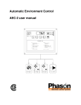
Proportional Environment Control
Model PEC user's guide
Limited warranty
This warranty applies only to the Phason Inc. (Phason) PEC. If you need warranty service, return the
product and original proof of purchase to your dealer.
Phason warrants the PEC subject to the following terms and conditions.
This warranty is valid only to the original purchaser of the product, for two years from the manufacturing
date. The manufacturing date is stated in the first eight digits of the serial number in the form yearmonth-day.
Phason hereby warrants that should this product fail because of improper workmanship, Phason will
repair the unit, effecting all necessary parts replacements without charge for either parts or labor.
Conditions
Installation must be done according to Phason’s enclosed installation instructions.
The product must not have been previously altered, modified, or repaired by anyone other than
Phason.
The product must not have been involved in an accident, misused, abused, or operated or installed
contrary to the instructions in our user and/or installation manuals. Phason's opinion about these
items is final.
The person requesting warranty service must be the original purchaser of the unit, and provide proof
of purchase upon request.
All transportation charges for products submitted for warranty must be paid by the purchaser.
Except to the extent prohibited by applicable law, no other warranties, whether expressed or implied,
including warranties of merchantability and fitness for a particular purpose, shall apply to this product.
Any implied warranties are excluded.
Phason is not liable for consequential damages caused by this product.
Phason does not assume or authorize any representatives, or other people, to assume any obligations or
liabilities, other than those specifically stated in this warranty.
Phason reserves the right to improve or alter the PEC without notice.
Service and technical assistance
Your dealer will be happy to answer all technical questions which will improve your use of the control. Be
prepared with the model number, serial number and necessary information before you place a call to your
dealer. If your control requires service when the warranty period has expired, return the unit to your dealer.
i
Table of contents
Features of the PEC.................................................................................................................................... 1
Getting started ............................................................................................................................................ 2
PEC electrical ratings.................................................................................................................................. 4
Equipment list ............................................................................................................................................. 5
Getting to know the PEC ............................................................................................................................ 6
Definition of terms ..................................................................................................................................................... 7
Adjusting the PEC....................................................................................................................................... 8
Selecting a new operating program ......................................................................................................................... 8
Changing parameter settings ................................................................................................................................... 9
Setup (hidden) parameters..................................................................................................................................... 11
Programming tips.................................................................................................................................................... 11
Reloading the factory programs ............................................................................................................................. 13
PEC operation........................................................................................................................................... 14
Parameter descriptions........................................................................................................................................... 17
Parameter ranges.................................................................................................................................................... 22
Setup (hidden) parameter ranges .......................................................................................................................... 23
Factory programs.................................................................................................................................................... 24
Setup (hidden) parameter table ............................................................................................................................. 25
Inlets.......................................................................................................................................................... 26
Manual operation .................................................................................................................................................... 26
Automatic operation................................................................................................................................................ 26
Testing and calibrating the inlet ............................................................................................................................. 27
Automatic inlet operation ........................................................................................................................................ 27
Methods of use ......................................................................................................................................... 29
Programs ................................................................................................................................................................. 29
Stage 5 proportional interval .................................................................................................................................. 29
Alarm messages ....................................................................................................................................... 30
Reasons for alarms to activate ............................................................................................................................... 30
Care and maintenance ............................................................................................................................. 32
Maintenance............................................................................................................................................................ 32
Power factor correction........................................................................................................................................... 33
ii
Appendix A: wiring diagrams ................................................................................................................... 34
Installation overview................................................................................................................................................ 35
General warnings .................................................................................................................................................... 36
Mounting instructions.............................................................................................................................................. 37
Grounding and sealing ........................................................................................................................................... 37
230 VAC control power ........................................................................................................................................... 38
115 VAC control power ........................................................................................................................................... 38
Temperature sensor................................................................................................................................................ 39
Four-zone averaging............................................................................................................................................... 39
Manually extending the sensor............................................................................................................................... 40
Alarm siren installation............................................................................................................................................ 41
Alarm panel installation........................................................................................................................................... 41
Linear actuator installation...................................................................................................................................... 42
DC linear actuator ................................................................................................................................................... 42
DC power supply .................................................................................................................................................... 43
AC linear actuator.................................................................................................................................................... 43
230 VAC heat/cool stages ...................................................................................................................................... 44
115 VAC heat/cool stages ...................................................................................................................................... 44
Heat/cool stage furnace.......................................................................................................................................... 45
230 VAC variable speed fan ................................................................................................................................... 46
115 VAC variable speed fan .................................................................................................................................. 46
Correct three-phase wiring ..................................................................................................................................... 47
Incorrect three-phase wiring ................................................................................................................................... 47
Heat/cool bypass switch......................................................................................................................................... 48
Variable stage bypass switch ................................................................................................................................. 48
Appendix B: test procedure...................................................................................................................... 49
Built-in test procedure............................................................................................................................................. 50
Input test.................................................................................................................................................................. 50
Memory test............................................................................................................................................................. 50
Display test .............................................................................................................................................................. 51
Variable stage test................................................................................................................................................... 51
Relay test................................................................................................................................................................. 52
Reset test................................................................................................................................................................. 52
Appendix C: troubleshooting guide ......................................................................................................... 53
Troubleshooting ...................................................................................................................................................... 54
Appendix D: blank program tables .......................................................................................................... 57
Blank parameter chart............................................................................................................................................. 58
Blank setup parameter chart .................................................................................................................................. 59
iii
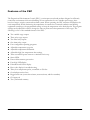
Features of the PEC
The Proportional Environment Control (PEC), is a microprocessor based product designed to efficiently
control the environment in livestock buildings. It has connections for two variable speed stages, three
heat/cool stages, an inlet system and an alarm system. When operating, the PEC measures and displays the
room temperature. While monitoring the temperature it controls the connected ventilation and heating
equipment according to the programmed settings to keep the temperature at the desired point. The program
settings can be adjusted in order to change the turn on points and other parameters of the stages. The
following is a list of the standard features of the PEC.
Two variable stage outputs
Three relay stage outputs
Two Inlet relay outputs
One alarm relay output
Four configurable operating programs
Adjustable temperature set-point
Adjustable temperature differential
Adjustable high/low temperature alert settings
Three-second full-power-turn-on to minimize fan ice-up
Status LEDs
Power-failure memory protection
Four-digit LED display
Fahrenheit and Celsius display
Error code display for troubleshooting
Thirty-foot temperature probe, extendable to 500 feet
Overload protection fuses
Rugged enclosure (corrosion resistant, water resistant, and fire retardant)
CSA approval
Two-year limited warranty
10242307
1
Getting started
Congratulations on the purchase of your new PEC environment control! This manual has been prepared to
help you get the utmost in satisfaction from your PEC. It contains detailed information regarding the
installation and operation of the control. The Getting Started section will step you through the installation
and configuration of your PEC. The following steps refer to other sections of this user's guide for additional
information. For this reason, it is not necessary to read through the entire document from front to back, but
rather in the order that the information is needed.
STEP 1
Checking ratings of equipment
Read the PEC electrical ratings on page 4.
Fill in the Equipment list on page 5.
WARNING: The equipment to be connected to the PEC control must not draw more
current than what the PEC stages are rated for. Use of equipment that is rated higher than
the PEC will result in damage to the control and will void the warranty.
STEP 2
Installation
STEP 3
Testing
2
Follow the instructions in Appendix A for installing and wiring the PEC and equipment.
Be sure to read the General Warnings section in Appendix A before installation.
Turn to Appendix B and follow the instructions there to test the operation of the
equipment installed and to ensure that it is connected properly.
2009-06-19
STEP 4
Setting up
STEP 5
Putting control into service
STEP 6
Read the PEC operation section starting on page 14.
Select the most useful factory program, on page 24.
Make changes to the program as desired, on page 9.
The INLETS section starting on page 26 describes how to calibrate the
inlet and program the PEC to control the inlet automatically.
Mark the changes in the Blank Program Tables in Appendix D.
Methods of use
10242307
Read through the Adjusting the PEC section starting on page 8 and get
familiar with the programming procedures.
Configure the PEC according to the type of equipment connected.
Mark the changes in the Blank Program Tables in Appendix D.
Read the Methods of use section on page 29.
3
PEC electrical ratings
Temperature sensor:
The standard temperature probe is 30 feet. Longer probes and extension cable
are available.
Feedback:
5.0 VDC. The feedback potentiometer must be 1K to 20 K Ω.
Alarm relay:
0.4 A at 125 VAC, 2 A at 30 VDC, resistive load
0.2 A at 125 VAC; 1 A at 30 VDC, inductive load
Inlet relays:
4.4 A at 120 VAC, 2.2 A at 230 VAC, 5 A at 30 VDC
Relay stages 3, 4, and 5:
4.4 A at 120 VAC, 2.2 A at 230 VAC, general-purpose (resistive)
1/6 HP at 230 VAC
360 W tungsten at 120 VAC
Variable stages:
7.5 A at 120/230 VAC, general-purpose (resistive)
5 FLA 120/230 VAC, PSC motor
1/3 HP at 120 VAC, 1/2 HP at 230 VAC, PSC motor
NOTE:
4
This is not a wiring diagram. All wiring diagrams are located in Appendix A.
2009-06-19
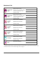
Equipment list
Make and model of fan(s):
Variable speed
stage 1
Maximum total current draw of fan(s):
(must not be greater than 7.5 A)
Operating voltage:
Make and model of fan(s):
Variable speed
stage 2
Maximum total current draw of fan(s):
(must not be greater than 7.5 A)
Operating voltage:
Make and model of fan/heater:
Cool/heat
stage 3
Maximum total current draw: *
Operating voltage:
Make and model of fan/heater:
Cool/heat
stage 4
Maximum total current draw: *
Operating voltage:
Make and model of fan/heater:
Cool/heat
stage 5
Maximum total current draw: *
Operating voltage:
Make and model of actuator:
Inlet stages
Maximum total current draw: *
Operating voltage:
Alarm relay connected to:
Alarm
* A power contactor must be used if the maximum total current draw is greater than the maximum ratings
of the internal relay. See the electrical ratings section on page 4.
10242307
5
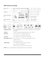
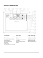
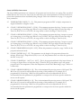
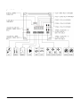
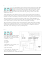
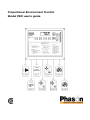
Getting to know the PEC
1 Program button
used to select the desired operating
program
2 Store button
used to save selected programs
and parameter settings in memory
3 Parameter button
used to scroll through the
parameter list
4 Digital display
shows the temperature and settings
6
5 Return button
used to return back to normal
operation
6 Down button
used to de
crease the value of a parameter
7 Up button
used to increase the value of a
parameter
8 Stage 1 indicator light
9 Stage 2 indicator light
10 Stage 3 indicator light
11 Stage 4 indicator light
12 Stage 5 indicator light
13 Close indicator light
14 Open indicator light
15 Complete parameter list
2009-06-19
Definition of terms
Normal operation
The PEC is in normal operation when it is displaying room temperature. When
alarms occur, the display will alternately flash the alarm signal and room temperature.
Programs
Programs consist of the Main, Differential, Inlet, Alarms and General parameters.
The PEC has four programs which can be selected and reprogrammed by the user.
Operating program
The PEC operates according to the parameters in the operating program. Any one of
the programs may be selected as the operating program.
Parameter list
The parameter list is printed on the front of the PEC and is also shown on page 22.
It is a list of all the parameters that may be programmed by the user.
Parameters
Parameters are the individual settings which may be programmed. See the Parameter
descriptions section on page 17 for an explanation for each of the parameters. There
are six parameter categories.
1) Main - The MAIN parameters control the main operation of the control.
2) Differential - These parameters are programmable differentials. They are the
number of degrees above or below the temperature set point the particular stage
starts or turns on.
3) Inlet - The INLET parameters control the movement of the inlet.
4) Alarms - These parameters set the point at which the temperature alarms activate.
5) General - GENERAL parameters are common to all programs. These parameters
have one setting which is used regardless of the operating program.
6) Setup - SETUP parameters control the overall operation of the unit. These
parameters have only one setting which is used regardless of the operating program.
10242307
7
Adjusting the PEC
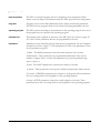
Selecting a new operating program
As livestock mature, often a change in the room climate is needed. The PEC has four different programs in
memory for different climate settings. Any one of the programs can be the operating program. In order to
change the operating program of the PEC, follow the instructions listed below. For a list of the factory
settings in the programs see Table 3, on page 24.
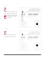
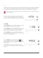
1. Press the PROG button once.
The PEC will display the current operating program, (A, B,
C, or D). The display will flash the program name and Pr.
2. Press the PROG button a number of times until the desired program is displayed.
By pressing the PROG button, the program names are
displayed one after another. To change to a different
operating program, press the PROG button until the
proper program is displayed.
3. Press the STORE button to enter the desired program into
memory.
When the correct program is displayed, pressing the
STORE button will tell the PEC to use the selected
program as the operating program. After Stor is
displayed, the PEC returns to normal operation.
8
2009-06-19
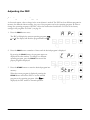
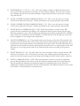
Changing parameter settings
Follow the steps below to view and/or edit the parameters in any program. After the parameters have been
edited, the changes should be marked in the Blank Program Tables in Appendix D for future reference.
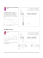
1. Press the PROG button until the program that you want to
edit is displayed.
The display will flash the program letter, (A to d) and Pr.
NOTE: If the operating program is to be edited, step 1
may be skipped. The parameters of the operating program
will be displayed by default.
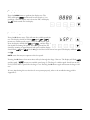
2. Press the PARM button once.
The first (left) digit shows the program that is being
edited.
The second digit indicates if the program is the operating
program. An o means the program is the operating
program, a blank means it is not the operating program.
The two right-most digits represent the parameter number that is being edited.
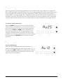
3. Press the UP or DOWN key to turn memory protect off.
The display will show Ao 0 and then oFF indicating
memory protect has been turned off. The parameters can
now be adjusted. If memory protect in not turned off, the
parameters can only be viewed. Attempting to adjust the
parameters while memory protect is on will result in an
Err message being displayed.
10242307
9
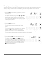
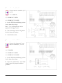
4. Press the PARM button to step through the parameter list
until the desired parameter is reached.
Refer to the front cover of the PEC control or on page 22
and 23 for the parameter lists.
5. Use the UP or DOWN buttons to adjust the setting.
The parameter can be adjusted to any value within the
parameter's range. The ranges are shown on page 22 and
23.
6. Press STORE to save the setting in memory.
The display will show Stor for 1 second indicating the
new setting has been stored in memory. If the PARM
button is pressed before pressing STORE the next
parameter will appear and the previous one will change
back to its previous setting.
Continue through the parameter list by pressing the PARM button and making changes to the settings
where needed. Follow the same procedure shown in steps 4 to 6.
7. To return to normal operation (displaying of room
temperature) at any time, press the RETURN button.
When RETURN is pressed, memory protect is automatically
turned back on. If a parameter has been changed but the
value has not been stored, pressing RETURN will change
the parameter's setting to the last stored setting and then
press RETURN again to return the control to normal
operation.
NOTE: If the PEC is left displaying a parameter it will automatically revert back to normal operation in one
minute. If STORE was not pressed the displayed parameter will change back to its previous value.
10
2009-06-19
Setup (hidden) parameters
The setup parameters should be programmed when the installation has been completed to configure the
PEC, and then generally the parameters do not need to be reprogrammed. When the setup parameters have
been programmed, the blank program table in Appendix D should be filled in with the new settings for
future reference. It is important that the Configuration sticker, included with the PEC, is marked correctly
and affixed to the side of the PEC when the setup parameters have been programmed. The Configuration
sticker provides a handy reference when you need to check the mode of operation of the staged outputs.
To edit the setup parameters
Press the PARM button once to enter the edit mode. If you
wish to edit the setup parameters, you must turn off memory
protect now. See page 9 to turn off the memory protection.
Next press the PROG and PARM buttons simultaneously to
access the setup parameters. The setup parameters can be
adjusted as desired and stored in the same way the normal
parameters can. After the setup parameters have been changed
and stored, press the RETURN button to return to normal
operation.
Programming tips
Scrolling backwards
When viewing or editing the parameters, sometimes it is
helpful to scroll backwards through the parameter list. To do
this, press the PARM and UP buttons simultaneously. Instead
of the PEC displaying the next parameter on the list, it will
display the previous parameter.
10242307
11
Selecting a parameter to edit
The parameters are stored in a table in memory which is similar to the Factory Program Table on page 24.
Any parameter in any program can be edited when memory protection has been turned off. Follow these
procedures when editing parameters to become more efficient.
To move down to the next parameter press the PARM button.
To move up or backwards to the previous parameter press the PARM and UP buttons simultaneously.
To move right press the PROG button until the desired program is displayed, then press the PARM
button once to edit the same parameter number that was being edited before.
To move
Press button(s)
↑
PARM
↓
PARM
→
PROG
and UP
An example where this method of programming is useful would be a situation where the temperature set
point of each program needs to be changed. This could be done by turning off memory protection and
changing the temperature set point in the operating program, (the operating program is displayed with an o
and the program name). Then press the PROG button two times to edit the next program. Press the PARM
button and edit the parameter. To continue to the next program press the PROG button again. Remember
that STORE must be pressed after each change to save the new setting in memory.
Fast editing
When editing the setting of a parameter by adjusting it up or
down, hold down either button and then press the other one.
This will change the setting ten times faster. If you want to
increase the setting, hold down the UP button and then press
the DOWN button. The setting will increase ten times faster. To
decrease the setting ten times faster, hold down the DOWN
button and then press the UP button.
12
2009-06-19
Reloading the factory programs
The factory programs can be reloaded if so desired, to replace the existing programs. If the existing
programs are not operating properly or need to be changed back to the original factory programs, follow the
steps below to reload the factory programs.
When the factory programs are reloaded, both of the existing programs including the setup
parameters will be replaced. The PEC will begin with program A as the operating program. The
programs and most importantly the setup parameters will need to be reprogrammed for the
equipment that is connected. Pay close attention to the Setup parameters for Stages 3, 4 and 5.
1. Turn off the power to the PEC.
2. Hold down the PROG and STORE buttons.
3. While holding the buttons down, turn the power back on.
The display will flash Stor for two seconds and then the
PEC will be in the normal operating mode and displaying
the room temperature.
10242307
13
PEC operation
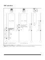
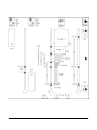
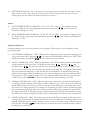
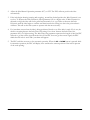
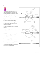
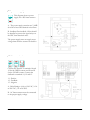
Figure 2:
14
PEC operation diagram—circled numbers correspond to the parameter numbers.
2009-06-19
10242307
15
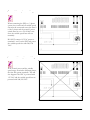
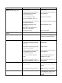
Figure 2 on page 14 shows the operation of each stage of the PEC. This particular diagram shows when the
stages will turn on and off when the PEC is operating according to the factory settings in program A. Some
settings are listed here but the entire factory program table can be found on page 24. The circled numbers
correspond to the parameter numbers. Use these numbers to cross reference the parameters in the diagram
to their descriptions. All stages have a programmable hysteresis, parameter 34.
Parameter settings
1
Temp Set (Start P-Band1)
2
Stage 1 Min Vent
3
Stage 2 Min Vent
4
Inlet Min
5
Stage 1 OSB
6
Stage 1 P-Band1
7
Stage 2 OSB
8
Stage 2 Start P-Band2
9
Stage 2 P-Band2
10 Stage 3 Turn On
11 Stage 4 Turn On
12 Stage 5 Turn On
13 Inlet Close-Set-Back
14 Position P-Band 1
15 Position P-Band 2
16 Position Stage 3
17 Position Stage 4
18 Position Stage 5
19 Low Temp Alarm
20 High Temp Alarm
85.0°F
20%
20%
20%
-5.0
1.5
0.0
2.0
1.5
4.0
6.0
-1.0
-5.0
40%
60%
80%
99%
99%
-5.0
10.0
NOTE: When the variable speed stages turn on, they will run
full speed for three seconds and then decrease to the required
speed.
Example
As an example, say the temperature is 75°F and rising. At this
point Stage 5 (heat) and the Low Temp Alarm will be on. The
Position Stage 5 parameter will not affect the inlet because
Stage 5 is set for heating operation. When the temperature
rises to 80°F, the Low Temp Alarm will turn off, the Stage 1
fan will turn on and the inlet will open to its minimum
setting. The Stage 1 fan will run at full speed for three
seconds and then slow down to the Minimum Ventilation
setting.
When the temperature reaches 84°F Stage 5 (heat) will turn
off. At 85°F the Stage 1 P-Band starts. While the temperature
rises in the P-Band, the Stage 1 fan will increase in speed and
the inlet will open proportionally to the temperature. At
86.5°F Stage 1 will be at full speed and the inlet will be open
to the Position P-Band 1 setting.
When the temperature rises to 87°F the Stage 2 P-Band starts. Since the Stage 2 fan has been off until now,
it will run full speed for three seconds and then slow down to the required speed. As the temperature rises
in the Stage 2 P-Band, the Stage 2 fan will increase in speed and the inlet will open proportionally to the
temperature. At 88.5°F the Stage 2 fan will be at full speed and the inlet will be open to the Position P-Band
2 setting.
At 89°F Stage 3 (cool) will turn on and the inlet will open to the Position Stage 3 setting.
At 91°F Stage 4 (cool) will turn on and the inlet will open to the Position Stage 4 setting.
When the temperature rises to 95°F the High Temperature Alarm turns on.
16
2009-06-19
Parameter descriptions
Main parameters
0
MEMORY PROTECT [On/Off] - ensures parameters are not changed by accident. Memory protect
must be turned off every time the parameters are edited. The memory protect parameter can not be
stored and is turned on automatically when the control returns to normal operation.
1
TEMPERATURE SET (Start P-Band 1) [32.0 - 110.0°F, 0.0 - 43.3°C] - is the target room
temperature. The differentials and alarms are referenced to this setting. It is the starting point of the
Stage 1 P-Band (parameter #6).
2
STAGE 1 MINIMUM VENTILATION [Minimum Idle (#21) - 99] - is the idle speed in percent of
full power at which the Stage 1 fan will idle at. It cannot be adjusted below the setting of the Minimum
Idle (#32) parameter.
3
STAGE 2 MINIMUM VENTILATION [Minimum Idle (#22) - 99] - is the idle speed in percent of
full power at which the Stage 2 fan will idle at. It cannot be adjusted below the setting of the Minimum
Idle (#33) parameter.
4
INLET MINIMUM [0 - 99] - is the percentage of opening the inlet will open to when the temperature
is in the inlet close-set-back region.
Differentials
5
STAGE 1 OFF-SET-BACK [IDLE, -20.0 - 0.0°F, -11.1 - 0.0°C] - is a range of degrees below the
Temp Set where the Stage 1 fan will be at idle speed, and below this range the fan will be off. Idle
means the fan will run at the Min Vent setting at all temperatures below the Temp Set. If Temp Set
(#1) is set to 80°F and Stage 1 Off-Set-Back (#5) is set at -8°F the fan will idle when the temperature
is between 72°F and 80°F, but will be off below 72°F.
6
STAGE 1 P-BAND1 [0.0 - 16.0°F, 0.0 - 8.9°C] - The proportional band is a range of degrees above
the Temp Set where the Stage 1 fan increases in speed proportionally to the temperature. If Temp Set
(#1), is set to 80°F and Stage 1 P-Band1 (#6) is set at 5°F the variable speed fan will start to increase
speed at 80°F and will be at full speed at 85°F .
7
STAGE 2 OFF-SET-BACK [IDLE, -20.0 - 0.0°F, -11.1 - 0.0°C] - is a range of degrees below the
Stage 2 Start P-Band2 (#8) where the Stage 2 fan will be at idle speed, and below this range the fan
will be off. Idle means the fan will run at the Min Vent setting at all temperatures below the Stage 2
Start P-Band2 (#8) setting. If Temp Set (#1) is set to 80°F, Start of P-Band Stage 2 (#8) is set to 10°F
and Stage 2 Off-Set-Back (#7) is set at -3°F, the Stage 2 fan will idle between 87°F and 90°F but will
be off below 87°F.
8
STAGE 2 START P-BAND2 [-10.0 - 15.0°F, -5.5 - 8.4°C, OFF] - is the number of degrees above or
below the Temp Set at which the Stage 2 proportional band starts. All Stage 2 differentials are with
respect to this setting. If the Temp Set (#1) is 80°F and this parameter (#8) is set to 10°F , the Stage 2
P-Band will start at 90°F .
10242307
17
9
STAGE 2 P-BAND2 [0.0 - 16.0°F, 0.0 - 8.9°C] - The proportional band is a range of degrees above
Stage 2 Start P-Band2 where the Stage 2 fan will increase in speed proportionally to the temperature. If
Temp Set (#1) is set to 80°F , Stage 2 Start P-Band2 (#8) is set to 10°F and Stage 2 P-Band2 (#9) is
set at 5°F , the Stage 2 variable speed fan will start to increase speed at 90°F and will be at full speed at
95°F .
10
STAGE 3 TURN ON [-10.0 - 15.0°F, -5.5 - 8.4°C, OFF] - is the number of degrees above or below
the Temp Set at which Stage 3 will turn on. If the Temp Set (#1) is set to 80°F and Stage 3 Turn On
(#10) is set to 5°F, Stage 3 will turn on at 85°F. The Stage 3 Operation (#26) parameter regulates what
mode Stage 3 operates in, heat or cool.
11
STAGE 4 TURN ON [-10.0 - 15.0°F, -5.5 - 8.4°C, OFF] - is the number of degrees above or below
the Temp Set at which Stage 4 will turn on. If the Temp Set (#1) is set to 80°F and Stage 4 Turn On
(#11) is set to 10°F, Stage 4 will turn on at 90°F. The Stage 4 Operation (#27) parameter regulates
what mode Stage 4 operates in, heat or cool.
12
STAGE 5 TURN ON [-10.0 - 15.0°F, -5.5 - 8.4°C, OFF] - is the number of degrees above or below
the Temp Set at which Stage 5 will turn on. If the Temp Set (#1) is set to 80°F and Stage 5 Turn On
(#12) is set to -5°F, Stage 5 will turn on at 75°F. The Stage 5 Operation (#28) parameter regulates
what mode Stage 5 operates in, heat or cool. Stage 5 will operate as a proportional interval timer if
Proportional (#29) is set to ON.
Inlet parameters
13
INLET CLOSE-SET-BACK [IDLE, -20.0 - 0.0°F , -11.1 - 0.0°C] - is a range of degrees below the
Temp Set where the inlet will be open to it's minimum setting (#4), and below this range the inlet will
be closed. When this parameter is programmed to IDLE, the inlet will be open at the minimum
position at all temperatures below the Temp Set. If Temp Set (#1) is set to 80°F and Inlet Close-SetBack (#13) is set at -8°F the inlet will be at the minimum position when the temperature is between
72°F and 80°F , but will be closed below 72°F .
14
POSITION P-BAND 1 [0 - 99] - is the amount of opening in percent that the inlet will open to when
the temperature is at the upper end of the stage 1 proportional band. The inlet will open
proportionally through out the Stage 1 P-Band1 (#6).
15
POSITION P-BAND 2 [0 - 99] - is the amount of opening in percent that the inlet will open to when
the temperature is at the upper end of the stage 2 proportional band. The inlet will open
proportionally through out the Stage 2 P-Band2 (#9).
16
POSITION STAGE 3 [0 - 99] - is the amount of opening in percent that the inlet will open to when
Stage 3 turns on (#10). This will only occur if stage 3 is set for cooling mode. If stage 3 is set for
heating mode, the inlet will not be affected when stage 3 turns on.
17
POSITION STAGE 4 [0 - 99] - is the amount of opening in percent that the inlet will open to when
Stage 4 turns on (#11). This will only occur if stage 4 is set for cooling mode. If stage 4 is set for
heating mode, the inlet will not be affected when stage 4 turns on.
18
2009-06-19
18
POSITION STAGE 5 [0 - 99] - is the amount of opening in percent that the inlet will open to when
Stage 5 turns on (#12). This will only occur if stage 5 is set for cooling mode. If stage 5 is set for
heating mode, the inlet will not be affected when stage 5 turns on.
Alarms
19
LOW TEMPERATURE ALARM [OFF, -36.0 - 0.0°F, -20.0 - 0.0°C] - is the number of degrees
below the Temp Set that a low temperature alarm will be generated, (A Lt). This alarm may be
disabled by adjusting it to OFF.
20
HIGH TEMPERATURE ALARM [0.0 - 36.0°F, 0.0 - 20.0°C, OFF] - is the number of degrees above
the Temp Set that a high temperature alarm will be generated, (A Ht). This alarm may be disabled by
adjusting it to OFF.
General parameters
General parameters have one setting common to all programs. This setting is in effect regardless of the
operating program.
21
LOW POWER ALARM [ON - OFF] - When the line voltage drops below the proper operating level,
a low power alarm will be displayed (A LP). This alarm may be disabled by adjusting it to OFF. When
disabled, the display will still flash A LP, but the alarm relay will not activate.
22
INLET ALARMS [ON - OFF] - When this parameter is ON, all inlet alarms will flash on the display
and the alarm relay will be activated. The alarms are Jam Open - A Jo, Jam Close - A Jc, and
Feedback alarm - A Fb. The jam open and jam close alarms appear when the PEC is trying to move
the inlet but does not receive the correct message back from the inlet. This can happen if the feedback
wires are connected backwards, or if the inlet has not been calibrated or is mechanically stuck. The
feedback alarm appears when the feedback wires have been damaged, shorted or disconnected. When
this parameter is off, the alarm messages will not be displayed and the alarm will not activate if these
conditions occur. Press RETURN to clear a jam alarm and retry the positioning of the inlet.
23
ALARM LATCHING [ON - OFF] - When this parameter is turned ON, all alarms will be displayed
on the PEC and will continue to flash after the alarm condition is gone. They can be reset by pressing
the RETURN button. This feature is useful to keep track of the alarms that occur during times when
the control is not being supervised. For example; in the morning the PEC could be checked for alarms
that occurred during the night and then the alarms could be cleared. If this parameter is turned OFF,
the display will only show the alarm when the condition is present. When the alarm condition is gone,
the alarm will no longer be displayed. NOTE: Only the alarm display will latch and not the alarm relay.
24
VENTILATION [ON - OFF] - When this parameter is turned OFF, the variable speed outputs and
cooling stages are turned off completely and all alarms will not be displayed. The heating stages are not
affected. Ventilation may be turned OFF when a room is vacant to conserve energy. When it is turned
OFF the PEC will display VoFF. DO NOT use this to shut down fans to work on the wiring. Ensure
the breakers are turned off.
10242307
19
Setup (HIDDEN) Parameters
The setup (hidden) parameters are common to all programs and can only have one setting. They are called
hidden because they can not be accessed in the same area as the normal parameters. This has been done to
protect these parameters from accidentally being changed. Follow the instructions on page 11 to program
these parameters.
25
TEMPERATURE UNITS [°F - °C] - This parameter programs the PEC to display temperature in
degrees Fahrenheit or degrees Celsius.
26
STAGE 3 OPERATION [HEAT - COOL] - This parameter programs the Stage 3 output to operate
as a heating stage or a cooling stage. When it is set to HEAT, the stage will be on below the Stage 3
Turn On (#10). If it is set to COOL, the stage will be on above the Stage 3 Turn On (#10).
27
STAGE 4 OPERATION [HEAT - COOL] - This parameter programs the Stage 4 output to operate
as a heating stage or a cooling stage. When it is set to HEAT, the stage will be on below the Stage 4
Turn On (#11). If it is set to COOL, the stage will be on above the Stage 4 Turn On (#11).
28
STAGE 5 OPERATION [HEAT - COOL] - This parameter programs the Stage 5 output to operate
as a heating stage or a cooling stage. When it is set to HEAT, the stage will be on below the Stage 5
Turn On (#12). If it is set to COOL, the stage will be on above the Stage 5 Turn On (#12).
29
STAGE 5 PROPORTIONAL [ON - OFF] - When this parameter is turned on, stage 5 will be in the
proportional interval mode.
30
STAGE 5 INTERVAL [5 - 25] - This parameter sets the length of the proportional interval in
minutes. When Stage 5 Proportional (#29) is set to off, this parameter does not affect the operation of
the PEC in any way.
31
STAGE 5 P-BAND [0.0 - 16.0°F, 0.0 - 8.9°C] - This is the proportional band of the interval timer. It
is a range of degrees above or below the Stage 5 Turn On (#12) point where stage 5 will operate
proportional to the temperature. When the temperature exceeds the P-Band range, stage 5 will be on
continuously.
32
STAGE 1 MINIMUM IDLE [0 - 99] - This is the minimum idle preset in percent of full speed. The
Min Vent (#2) can not be adjusted below the setting of this parameter. For example; if it is
programmed to 20 the Stage 1 Min Vent (#2) parameter can not be adjusted below 20. It is
recommended that this parameter be programmed to correspond to the lowest speed at which the
motor can still operate.
33
STAGE 2 MINIMUM IDLE [0 - 99] - This is the minimum idle preset in percent of full speed. The
Min Vent (#3) can not be adjusted below the setting of this parameter. For example; if it is
programmed to 20 the Stage 2 Min Vent (#3) parameter can not be adjusted below 20. It is
recommended that this parameter be programmed to correspond to the lowest speed at which the
motor can still operate.
20
2009-06-19
34
HYSTERESIS [0.5 - 2.5°F, 0.3 - 1.4°C] - This is the number of degrees of difference between the
turn-on point and turn-off point for all stages. It is the number of degrees above the turn-on point
that a heating stage will turn off, and the number of degrees below the turn-on point that a cooling
stage will turn off.
35
STAGE 1 POWER FACTOR COMPENSATION [5 - 25] - This is set at the factory to 10 and
should only be adjusted if the Stage 1 variable speed fan does not operate properly with the PEC.
36
STAGE 2 POWER FACTOR COMPENSATION [5 - 25] - This is set at the factory to 10 and
should only be adjusted if the Stage 2 variable speed fan does not operate properly with the PEC.
37
INLET MANUAL OPERATION [ON - OFF] - When this parameter is turned off, the PEC
controls the inlet automatically according to the temperature and the position setting for each stage.
When this parameter is set to ON the inlet can be manually positioned by pressing the UP or DOWN
button. Press UP to OPEN the inlet and DOWN to CLOSE the inlet. The inlet will stay in the same
position regardless of any changes in the temperature.
38
INLET HYSTERESIS [0 - 10] - This parameter adjusts the accuracy of the inlet. The hysteresis is the
tolerance in percent that the inlet can be resting away from the desired position. This parameter must
be adjusted to suit the characteristics of the particular inlet control system. If the Inlet Hysteresis is too
small, the inlet will oscillate around the desired position and will not sit at a steady position. If the Inlet
Hysteresis is set too large, the inlet will not be positioned with accuracy according to the position
settings.
39
INLET TIME OUT [5 - 60] - The Inlet Time Out is the total length of time in seconds that the PEC
will wait for the inlet to move. If the inlet does not move the amount required within the time out
period, the inlet will stop moving and a jam alarm will be displayed if Inlet Alarms (#22) is turned on.
40
INLET CALIBRATION [ON - OFF] - When this parameter is turned on it starts the calibration
process. During calibration, the inlet is closed, then opened completely and then closed completely.
This will program the minimum and maximum ranges for the particular inlet system. When the
calibration is complete the parameter will turn off automatically. The calibration must be done in order
for the PEC to control the inlets in automatic mode.
10242307
21
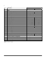
Parameter ranges
#
0
1
2
3
4
5
6
7
8
9
10
11
12
13
14
15
16
17
18
19
20
21
22
23
24
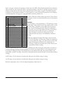
Table 1:
22
Parameters
Main
Memory Protect
Temp Set (Start P-Band1)
Stage 1 Min Vent
Stage 2 Min Vent
Inlet Min
Differential
Stage 1 Off-Set-Back
Stage 1 P-Band1
Stage 2 Off-Set-Back
Stage 2 Start P-Band2
Stage 2 P-Band2
Stage 3 Turn On
Stage 4 Turn On
Stage 5 Turn On
Inlet
Inlet Close-Set-Back
Position P-Band 1
Position P-Band 2
Position Stage 3
Position Stage 4
Position Stage 5
Alarms
Low Temp Alarm
High Temp Alarm
General (common to all programs)
Low Power Alarm
Inlet Alarms
Alarm Latching
Ventilation
Ranges
°F
°C
ON / OFF
32.0 - 110.0
0.0 - 43.3
Min Idle (parm #32) - 99
Min Idle (parm #33) - 99
0 - 99
IDLE, -20.0 - 0.0
0.0 - 16.0
IDLE, -20.0 - 0.0
-10.0 - 15.0, OFF
0.0 - 16.0
-10.0 - 15.0, OFF
-10.0 - 15.0, OFF
-10.0 - 15.0, OFF
IDLE, -11.1 - 0.0
0.0 - 8.9
IDLE, -11.1 - 0.0
-5.5 - 8.4, OFF
0.0 - 8.9
-5.5 - 8.4, OFF
-5.5 - 8.4, OFF
-5.5 - 8.4, OFF
IDLE, -20.0 - 0.0
0 – 99
0 – 99
0 – 99
0 – 99
0 – 99
IDLE, -11.1 - 0.0
OFF, -36.0 - 0.0
0.0 - 36.0, OFF
OFF, -20.0 - 0.0
0.0 - 20.0, OFF
ON / OFF
ON / OFF
ON / OFF
ON / OFF
Parameter ranges
2009-06-19
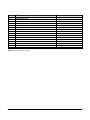
Setup (hidden) parameter ranges
#
25
26
27
28
29
30
31
32
33
34
35
36
37
38
39
40
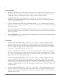
Table 2:
SETUP (Hidden) parameters common to all programs
Temperature Units
Stage 3 Operation
Stage 4 Operation
Stage 5 Operation
Stage 5 Proportional
Stage 5 Interval
Stage 5 P-Band
Stage 1 Minimum Idle
Stage 2 Minimum Idle
Hysteresis
Stage 1 P.F. Compensation
Stage 2 P.F. Compensation
Inlet Manual Operation
Inlet Hysteresis
Inlet Time Out
Inlet Calibration
Range
F/C
HEAT / COOL
HEAT / COOL
HEAT / COOL
ON / OFF
5 - 25
0.0 - 16.0°F 0.0 - 8.9°C
0 - 99
0 - 99
0.5 - 2.5°F 0.3 - 1.4°C
5 - 25
5 - 25
ON / OFF
0 - 10
5 - 60
ON / OFF
Setup parameter ranges
10242307
23
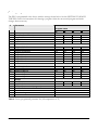
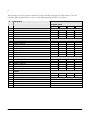
Factory programs
The PEC is programmed at the factory with the settings shown below. See the GETTING TO KNOW
THE PEC section for instructions for selecting a program. Select the most useful program and make
changes where necessary.
#
Parameters
Program names
1
2
3
4
5
6
7
8
9
10
11
12
13
14
15
16
17
18
19
20
21
22
23
24
Table 3:
24
Main
Temp Set (Start P-Band1)
Stage 1 Min Vent
Stage 2 Min Vent
Inlet Min
Differential
Stage 1 Off-Set-Back
Stage 1 P-Band1
Stage 2 Off-Set-Back
Stage 2 Start P-Band2
Stage 2 P-Band2
Stage 3 Turn On
Stage 4 Turn On
Stage 5 Turn On
Inlet
Inlet Close-Set-Back
Position P-Band 1
Position P-Band 2
Position Stage 3
Position Stage 4
Position Stage 5
Alarms
Low Temp Alarm
High Temp Alarm
General (common to all programs)
Low Power Alarm
Inlet Alarms
Alarm Latching
Ventilation
A
b
C
d
85.0
20
20
20
80.0
20
20
20
75.0
30
30
30
70.0
30
30
30
-5.0
1.5
0.0
2.0
1.5
4.0
6.0
-1.0
-5.0
2.0
0.0
2.0
2.0
5.0
7.0
-1.0
-5.0
2.0
0.0
2.5
2.0
5.0
7.0
-1.0
-5.0
3.0
0.0
3.0
3.0
7.0
9.0
-1.0
-5.0
40
60
80
99
99
-5.0
40
60
80
99
99
-5.0
40
60
80
99
99
-5.0
40
60
80
99
99
-5.0
10.0
-5.0
10.0
-5.0
15.0
-5.0
15.0
ON
ON
ON
ON
Factory programmed parameter list (All temperatures in ºF)
2009-06-19
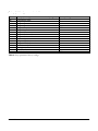
Setup (hidden) parameter table
#
25
26
27
28
29
30
31
32
33
34
35
36
37
38
39
40
Table 4:
Setup (hidden) parameters common to all programs
Temperature Units
Stage 3 Operation
Stage 4 Operation
Stage 5 Operation
Stage 5 Proportional
Stage 5 Interval
Stage 5 P-Band
Stage 1 Minimum Idle
Stage 2 Minimum Idle
Hysteresis
Stage 1 P.F. Compensation
Stage 2 P.F. Compensation
Inlet Manual Operation
Inlet Hysteresis
Inlet Time Out
Inlet Calibration
Factory setting
F
Cool
Cool
Heat
OFF
10
2
20
20
0.5
10
10
ON
2
10
OFF
Setup parameter factory settings
10242307
25
Inlets
Inlets can be controlled automatically or manually by the PEC. The type of operation is selected by changing
the setting of the parameter Inlet Manual Operation (parameter # 37). When the Inlet Manual Operation
parameter is set to OFF the inlets will be controlled automatically.
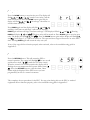
Manual operation
In manual operation, the inlets can be positioned by pressing the UP and DOWN buttons while in normal
operation. Pressing the UP button will open the inlets. The display will flash oPEn and the current position
in percent of the maximum opening. Pressing the DOWN button will close the inlets. The display will flash
CLoS and the current position in percent of the maximum opening. When the inlet is adjusted to the desired
position it will not move regardless of the temperature until the UP or DOWN buttons are pressed again.
Automatic operation
In automatic operation, the PEC will position the inlets automatically according to the room temperature. In
general, as the variable speed fans speed up and cooling stages turn on the inlets will be opened, but as the
temperature decreases and the fans slow down and cooling stages turn off the inlets will be closed. Adjust
the Inlet Hysteresis (parameter #38) and Inlet Time Out (parameter #39) to fine tune the operation of the
inlets. Adjust the position settings (parameters #14 - 18) to set the position of the inlets for each stage pband or turn on. The inlets should open farther as each fan turns on to allow more air into the building as
more air is being pushed out by the fans. If the UP or DOWN button is pressed the PEC will display Auto
and the current position of the inlet.
26
2009-06-19
Testing and calibrating the inlet
Follow these steps to test and calibrate the inlet to prepare it for use.
1. When the PEC is turned on for the first time, the inlets can be positioned manually. At the factory Inlet
Manual Operation, parameter #37, is set to ON. When Manual Operation is on, pressing the UP button
will open the inlets and the DOWN button will close the inlets. Check to see that the inlet moves in the
proper direction when pressing the UP and DOWN buttons. If the inlet moves in the opposite direction
the open and close wires are reversed. Correct the wiring and retest.
WARNING:
always turn off all power before removing the cover and making changes to the wiring.
2. Press and hold the UP or DOWN button and watch the inlet position reading. When the inlet is opening
the position reading should increase and, when the inlet is closing the position reading should decrease.
If the position reading is changing in the opposite direction the feedback wires are reversed. Turn off
the power and change the negative and positive wires around to reverse the direction of the feedback.
Now retest the position reading.
3. Press the DOWN button to move the inlet to its fully closed position. Adjust the internal limit switch in
the actuator to this position. This switch stops the actuator from closing further.
4. Press the UP button to move the inlet to its fully opened position. Adjust the internal limit switch in the
actuator to this position. This switch stops the actuator from opening further.
5. Start the calibration process by adjusting Inlet Calibration, parameter #40 to ON. The calibration
process will open and close the inlet and detect the location of the limit switches. When calibrated, the
fully closed position will be 0% and the fully open position will be 100%. The calibration will take a
number of minutes but can be aborted at any time by pressing the RETURN button. If the calibration
process is aborted the inlet will not be controlled properly by the PEC. If the calibration does not work
check the limit switches and restart the calibration. If the calibration still does not work, see the
Troubleshooting section in Appendix C.
The inlet is now calibrated and ready for use.
Automatic inlet operation
The following steps explain how to program the PEC to control the inlet automatically. The inlet should be
tested and calibrated before starting this section, see Testing and Calibrating above. If the inlet has been
tested and calibrated continue with these steps.
1. When the inlet is controlled automatically by the PEC it is positioned according to the settings for
parameter 4 and parameters 14 to 18. These parameters should be programmed so the inlet opens wider
as more stages turn on. In order to know what to program these parameters to, adjust the inlet by
pressing the UP and DOWN buttons while in manual operation and take note of the position reading for
each of the desired positions. The inlet should open further each time another stage turns on. When the
desired position reading is known the parameter can be programmed to the correct setting.
10242307
27
2. Adjust the Inlet Manual Operation parameter #37, to OFF. The PEC will now position the inlet
automatically.
3. If the inlet begins hunting (starting and stopping), around the desired position the Inlet Hysteresis is set
too low. To increase the Inlet Hysteresis, adjust parameter #38 to a higher value. If Inlet Hysteresis is
adjusted too high the inlet will not be positioned accurately. It is a good idea to decrease the Inlet
Hysteresis until the inlet begins to oscillate and then increase the setting just above the point where it
oscillates. This will set the inlet system to operate with the most accuracy.
4. If a jam alarm occurs when the inlet is being positioned, check to see if the inlet is stuck. If it is not, the
alarm is occurring because the Inlet Time Out setting is too short. Increase the Inlet Time Out,
parameter #39, to a higher setting. The Inlet Time Out parameter represents the length of time the PEC
will wait to get the correct signal from the inlet. If the PEC does not get the correct signal, the PEC
thinks that the inlet is stuck and a jam alarm will appear.
5. The PEC and inlet are now set for automatic operation. When the UP or DOWN button is pressed while
in automatic operation, the PEC will display Auto and then the current position of the inlet in percent
of the total opening.
28
2009-06-19
Methods of use
Programs
The PEC has four programs which can be selected as the operating program. To take advantage of the
programs, adjust them for different climate settings. They can be used for different kinds of livestock or
used at different stages of maturity for the livestock. Time is saved by simply changing the operating
program, instead of adjusting every parameter. Remember to mark all changes to the programs in the Blank
Program Tables in Appendix D to keep track of the settings.
Stage 5 proportional interval
Stage 5 can be programmed to operate as a proportional cycle timer. When Stage 5 operates as a
proportional cycle timer it provides better control of the temperature and more efficient operation. To do
this, Stage 5 will be on for a portion of the cycle or interval. The time Stage 5 is on will change depending
on the temperature.
To program, set Stage 5 Proportional (parameter #29) to on. This feature works when the Stage 5
Operation (parameter #28) is set to either heat or cool. The Stage 5 Interval Length (parameter #30) is
adjustable between 5 and 25 minutes. The Stage 5 P-Band (parameter #31) begins at the Stage 5 Turn On
point (parameter #12). When the temperature is within the P-Band range, Stage 5 will be turned on for a
portion of the interval. Stage 5 will cycle on and off once during one interval. The on time and off time will
change proportionally to the change in temperature. If the temperature exceeds the P-Band, Stage 5 will be
on all the time.
10242307
29
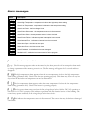
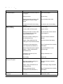
Alarm messages
Alarm
Description
Error - an incorrect key has been pressed
Alarm High Temperature - temperature is above the high temp alarm setting
Alarm Low Temperature - temperature is below the low temp alarm setting
Alarm Low Power - the line voltage is low
Alarm Probe Disconnect - the temperature sensor is disconnected
Alarm Probe Short - the temperature sensor is short circuited
Alarm Power Failure - indicates a power interruption has occurred
Alarm Internal Error - indicates an internal error has occurred
Alarm Jam Open - the inlet can not open
Alarm Jam Close - the inlet can not close
Alarm Feedback - the feedback wires are damaged
Ventilation Off - ventilation has been turned off in the program
Reasons for alarms to activate
The Err message appears when an incorrect key has been pressed or if an attempt has been made
to change a parameter while memory protect is on. The Err message will appear for 2 seconds and then
disappear.
The high temperature alarm appears when the room temperature is above the high temperature
alarm setting (parameter #20). Check if the fans are operating properly. This alarm may occur on very hot
days when the desired room temperature can not be maintained.
The low temperature alarm appears when the room temperature is below the low temperature
alarm setting (parameter #19). Check if the heater is operating properly.
The low power alarm turns on when the line voltage drops below 180 for 230 VAC operation or
below 90 for 115 VAC operation. This indicates a problem with the electrical service of the building. The
control may operate erratically if the voltage drops below these levels.
This indicates the temperature sensor is disconnected. The sensor wire may be broken or damaged
somewhere.
30
2009-06-19
This alarm indicates the temperature sensor is short circuited. The sensor or wire may be damaged
somewhere.
NOTE:
When a A Pd or a A PS alarm occurs, the heating and cooling stages will turn off and the variable
stages will run at idle speed.
The Power Failure alarm appears when there has been an interruption in the power. The control
will operate properly and the alarm can be cleared by pressing the RETURN button.
When this alarm appears it indicates an internal error has occurred. To clear this alarm check
through the parameters; adjust and store the ones that are incorrect. Next, turn the power off and then back
on and the alarm will clear. NOTE: A parameter must be changed and stored and the power turned off and
on before the alarm will be cleared. Another way to clear the alarm is downloading the factory programs.
This will reset all the parameters to the factory settings and then they must be programmed to the desired
settings again. Consult your dealer or Phason for information to prevent this problem from happening
again.
A jam open alarm appears when the PEC is trying to open the inlet but does not receive the
correct response from the positioning motor. This may happen if the inlet is mechanically stuck or the
feedback wires are reversed. Also, the jam open alarm may occur if the inlet has not been calibrated.
A jam close alarm appears when the PEC is trying to close the inlet but does not receive the
correct response from the positioning motor. This may happen if the inlet is mechanically stuck or the
feedback wires are reversed. Also, the jam close alarm may occur if the inlet has not been calibrated.
A feedback alarm occurs when the feedback wires are short circuited or damaged.
VoFF is displayed when VENTILATION (parameter #24), is turned OFF. When this is displayed,
the variable speed stages and the cooling stages will be turned off. The heating stage(s) will operate
normally.
10242307
31
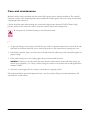
Care and maintenance
Moisture will not cause a problem with the control if the proper care is taken in installation. The control's
enclosure is made of fire retardant plastic and is sealed with a rubber gasket. The sensor entry is sealed with
a liquid tight cable connector.
Caution should be taken when washing the room with a high pressure washer. DO NOT direct a high
pressure washer at the control. In order to clean the control, wipe it with a damp cloth.
Be sure power is off before cleaning to avoid electrical shock.
Maintenance
1. To prevent damage to the control, after the first two weeks of operation remove the cover from the unit
and check for moisture inside. Be sure to turn off the power to the control before opening the cover.
2. If moisture is present, wipe it out with a dry cloth and check the cable entry points and rubber gasket for
proper sealing.
3. If the cable connectors are not sealing, apply silicon sealant around the cable.
WARNING:
If silicone is used, be aware that some silicone sealants release acetic acid while curing. Let
silicone cure completely (1 to 3 days), before closing the control or the control may be damaged and the
warranty VOID.
4. Check the control again after two weeks to ensure that it is properly sealed.
The control should be opened and inspected once a year for moisture. Proper care and maintenance will
extend the life of the control.
32
2009-06-19
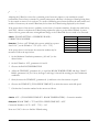
Power factor correction
Adjusting the P-Band to correct for a particular power factor may improve your ventilation system's
performance. Power factor correction is generally unnecessary and there is no danger of damage being done
to the control or motor if it is not done. As a result of different power factors between the many makes and
models of fan motors, the actual P-Band may be less then the P-Band setting displayed by the control.
If the power factor of the motor is available, use the chart of correction numbers, (listed in the table below),
and CALC 1 below to calculate the P-Band setting required in order to get the desired P-Band. A power
factor of 0.8 or greater will cause an insignificant change to the P-Band and does not need to be corrected.
CALC 1:
P-BAND SETTING = DESIRED P-BAND x
CORRECTION NUMBER
Example 1:
To have a 6°F P-Band with a motor which has a power
factor of 0.7, set the P-Band to 7.5°F. (6°F x 1.25 = 7.5°F)
If the power factor is not known the correction number may be
measured. Follow the steps below.
Power factor
1.0
0.9
0.8
0.7
0.6
0.5
Table 5: Power
Correction
1.00
1.05
1.10
1.25
1.33
1.60
factor correction
1. Set the Minimum Ventilation parameters, (# 2 and 3) to the
desired values.
2. Set the P-Bands to 10°F , parameters # 6 and 9.
3. Observe the ROOM TEMPERATURE.
4. Adjust the TEMP SET, (parameter # 1) to equal the ROOM TEMPERATURE and Stage 2 Start PBand2, (parameter # 8) to 0. Now, the Stage 1 and Stage 2 fans will be running just above minimum
ventilation.
5. Slowly decrease the TEMP SET, (parameter # 1) and listen to the fans increase in speed.
6. Observe the TEMP SET, (FULL SPEED TEMP SET) at which the motors reach full speed.
7. Calculate the Correction number for the motors as follows:
CALC 2:
10°F ÷ (FULL SPEED TEMP SET - ROOM TEMPERATURE) = Correction number
Example 2:
ROOM TEMP = 75°F and FULL SPEED TEMP SET = 82°F
Correction Number = 10°F ÷ (82°F - 75°F) = 1.43
Now use CALC 1 above to find the P-Band setting.
10242307
33
Appendix A: wiring diagrams
34
Installation overview on page 35
General warnings on page 36
Mounting instructions on page 37
Grounding and sealing on page 37
230 VAC control power on page 38
115 VAC control power on page 38
Temperature sensor on page 39
Four-zone averaging on page 39
Manually extending the sensor on page 40
Alarm siren installation en page 41
Alarm panel installation on page 41
Linear actuator installation on page 42
DC linear actuator on page 42
DC power supply on page 43
AC linear actuator on page 43
230 VAC heat/cool stages on page 44
115 VAC heat/cool stages on page 44
Heat/cool stage furnace on page 45
230 VAC variable speed fan on page 46
115 VAC variable speed fan on page 46
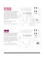
Correct three-phase wiring on page 47
Incorrect three-phase wiring on page 47
Heat/cool bypass switch on page 48
Variable stage bypass switch on page 48
2009-06-19
Installation overview
10242307
35
General warnings
Be sure power is off before doing any wiring.
Install all equipment according to the applicable local electrical codes.
The PEC should be installed by a qualified electrician.
Most variable speed fan motors draw more current at fractional speeds than at full speed. Fan motor
specifications show current draw at full speed. The increase in current draw may be as much as two times
the rated current. Current over 7.5 Amps will cause overheating and eventual failure of the PEC. Please
check current requirements for the fan motor by either measuring current draw at all speeds from idle to full
speed or consult the dealer for information on the particular fan.
CAUTION:
Only permanent split capacitor motors appropriate for variable speed control, or shaded pole
motors, can be used on the variable stages.
ATTENTION: Seulement moteurs du condensateur fendus permanents approprient pour contrôle de la
vitesse variable ou ont ombragé des moteurs de la perche, peut être utilisé sur les étapes variables.
DO NOT mount power contactors inside the PEC enclosure. Power contactors create electrical noise
which may cause the PEC to work improperly.
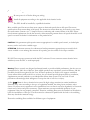
Warning:
Phason controls are designed and manufactured to provide reliable performance, but they are not
guaranteed to be 100% free of defects. Even reliable products may experience occasional failures, and this
possibility should be recognized by the User. If Phason products are used in a life support ventilation
system where failure could result in loss or injury, the user should provide adequate back-up ventilation,
supplementary natural ventilation or an independent failure alarm system. The user's lack of such
precautions acknowledges their willingness to accept the risk of such loss or injury.
A false 'A PF' alarm is due to electrical noise caused by high voltage transients in certain installations.
Electrical noise varies according to the type of equipment installed, the wiring layout and many other
factors. It's effects are not apparent in most installations but over time it can cause degradation of electronic
circuits and of relays and power contactors. These transients can cause unreliable operation of your
equipment if they are not properly controlled. Therefore, snubbing filters must be installed on all inductive
loads for installations of this type. The filters must be connected in parallel with the load so the snubbing
filter may absorb the transient energy.
Phason has snubbing filters available for different types of equipment.
36
2009-06-19
Mounting instructions
To mount the PEC, remove the four screws in the front cover and lift off the cover. The cover can be
unplugged from the bottom to make wiring easier. Mount the box to the wall with the four wood screws
provided with the control. Insert the screws into the large holes in each corner of the box and tighten.
Use the knockouts provided at the bottom of the enclosure for mounting cable connectors. DO NOT make
additional holes in the enclosure. This should not be done and will void the warranty! All wires should enter
the enclosure through the electrical-knockout holes provided and all grounds should be connected to the
ground plate. When installing a control, close attention should be taken to route the wires, inside the
control, away from the control's electronics so that wires are not draped across the components which may
result in a part being broken or damaged which will affect the reliability of your control.
DO NOT mount the bottom enclosure rotated 180o which places the electric-knockouts at the top of the
enclosure. This should not be done and may void warranty! When this is done corrosion causing moisture is
more likely to enter the control and wiring will be prone to contact with the electronic circuitry which may
cause damage to components as stated above.
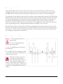
Grounding and sealing
A - Connect all ground wires to
ground studs.
B - Use 3/4" liquid tight wire
connectors for large holes.
C - Use 1/2" liquid tight wire connectors
for small holes.
D - Use RTV silicone or equivalent sealant
to seal cable entry points if liquid tight wire
connectors are not used.
If silicone is used, be aware that
some silicone sealants release
acetic acid while curing. This can
cause corrosion damage to the
control. Let the silicone cure completely (1
to 3 days), before closing the control or the
control may be damaged and the warranty
VOID.
10242307
37
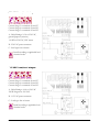
230 VAC control power
Connect the power to terminals 1 and 2.
A) Set switch to the 230 VAC position.
See page 47, for instructions for
connecting the PEC to three
phase power.
115 VAC control power
Connect power to terminals 1 and 2.
A) Set switch to 115 VAC position
38
2009-06-19
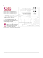
Temperature sensor
Connect the sensor to terminals 4
and 5.
A) The temperature sensor can be
extended if so desired. You may purchase
an extended sensor or extend a sensor
manually. To manually extend the sensor,
follow the instructions on the following
page.
Do not run the probe cable in the same
conduit as AC power cables.
Do not run the sensor cable beside AC
power cables or near electrical equipment.
When crossing other cables or power lines,
cross them at a 90 degree angle.
Four-zone averaging
Connect the sensor to terminals 4
and 5.
The PEC is capable of monitoring the
temperature in four areas and operating
accordingly to the average. Additional
probes are available. To manually extend
the sensor, follow the instructions on the
following page.
A) The PEC can operate with one or four
probes connected.
10242307
39
Manually extending the sensor
To extend the sensor, use 2 wire 18 or 20
AWG jacketed cable. To splice two wires
together follow the steps below and refer to
the diagram.
A) Slide pieces of heat shrink tubing on the
wire ends as shown.
B) Strip the ends of wire and twist together.
C) Using a soldering iron and solder,
connect the twisted wire ends together.
D) Slide the heat shrink tubing over the
soldered connection.
E) Heat the tubing with a hot air gun (paint
stripper).
F) When finished, the splice should be
completely sealed.
NOTE:
If the unit operates erratically with
the extended sensor, try running the
extended sensor on a different path or
shortening it.
Do not run the probe cable in the same
conduit as AC power cables.
Do not run the sensor cable beside AC
power cables or near electrical equipment.
When crossing other cables or power lines,
cross them at a 90 degree angle.
40
2009-06-19
Alarm siren installation
Connect alarm to terminals 14, 15
and 16.
14 - COMMON
15 - NORMALLY OPEN
16 - NORMALLY CLOSED
A - See the PEC Electrical Ratings section
for the alarm relay ratings.
B & C - Use a backup battery and an
appropriate charging system.
D - The siren ratings must not be greater
than the alarm relay ratings.
E - Alarm disable switch.
Alarm panel installation
Connect the alarm panel / autodialer to terminals 14, 15 or 16.
14 - COMMON
15 - NORMALLY OPEN
16 - NORMALLY CLOSED
A - See the PEC Electrical Ratings section
for the alarm relay ratings.
B - Consult the Alarm Panel / Auto-dialer
owner's manual for proper installation
guidelines.
10242307
41
Linear actuator installation
In a typical installation, a linear actuator is physically connected to the inlets with a
network of cables and pulleys. These inlets are generally small and located in the
ceiling or walls and are usually spring loaded to aid in closing the inlet. In other
installations, larger inlets may be connected to the actuator directly or with a
linking arm. A system operates with the most precision when using the largest amount of stroke that is
feasible with the actuator.
In order for the PEC to control the linear actuator, the actuator must have limit switches and a feedback
potentiometer. Most linear actuators are available with internal adjustable limit switches and potentiometer
feedback. A 10k ohm 10 turn feedback potentiometer is desired but it can range between 1k and 100k ohms.
Phason recommends the use of Grainger part # 5A652, von Weise (Fasco) model # V00099BA76, or
equivalent DC linear actuator which can be used with a DC power supply. Depending on your equipment,
you may require a bracket to prevent the actuator arm from rotating while it is extending.
PEC controls that have a DC linear actuator connected should have a snubber filter installed. It should be
installed across (in parallel with) the actuator, so it can absorb the transient energy that the actuator motor
generates which will extend the service life of the control's signal relays. A snubber filter is included in
Phason's DC Actuator Power Supply or may be purchased seperately.
DC linear actuator
Connect the actuator to terminals 18 and 19
for the OPEN contact and 20 and 21 for
the CLOSE contact. Connect the feedback
to terminals 11, 12 and 13.
11 - Positive
12 - Feedback
13 - Negative
A - Relay Ratings: 4.4 A at 120 VAC, 2.2 A
at 230 VAC, 5 A at 30 VDC
B - DC Linear Actuator
C - Power supply for a DC linear actuator.
PEC Controls that have a DC linear
actuator connected must have a snubber filter installed.
42
2009-06-19
DC power supply
This diagram shows a power
supply for a DC linear actuator.
A - The power supply contains two 5 AMP
slow-blow fuses and electrical noise filters.
B - Snubber filter installed. A filter should
be installed to protect the signal relays on
the PEC from electrical noise.
The power supply must not supply more
voltage than what the actuator is rated for.
AC linear actuator
Connect the actuator to terminals 18 and
19 for the OPEN contact and 20 and 21
for the CLOSE contact. Connect the
feedback to terminals 11, 12 and 13.
11 - Positive
12 - Feedback
13 - Negative
A - Relay Ratings: 4.4 A at 120 VAC, 2.2 A
at 230 VAC, 5 A at 30 VDC
B - AC linear actuator must be connected
to the proper supply voltage.
10242307
43
230 VAC heat/cool stages
Connect Stage 3 to terminals 26 and 27.
Connect Stage 4 to terminals 24 and 25.
Connect Stage 5 to terminals 22 and 23.
A - Relay Ratings: 2.2 A at 230 VAC,
general-purpose (resistive)
1/6 HP at 230 VAC, PSC motor
B - 230 VAC power contactor.
C- Load type: fan or heater.
Install according to applicable local
electrical codes.
115 VAC heat/cool stages
Connect Stage 3 to terminals 26 and 27.
Connect Stage 4 to terminals 24 and 25.
Connect Stage 5 to terminals 22 and 23.
A - Relay Ratings: 4.4 A at 120 VAC
360 W tungsten at 120 VAC
B - 115 VAC power contactor.
C - Load type: fan or heater.
Install according to applicable local
electrical codes
44
2009-06-19
Heat/cool stage furnace
Connect Stage 3 to terminals 26 and 27.
Connect Stage 4 to terminals 24 and 25.
Connect Stage 5 to terminals 22 and 23.
A - Relay Ratings: 4.4 A at 120 VAC, 2.2 A
at 230 VAC, general-purpose (resistive)
1/6 HP at 230 VAC, PSC motor
B - This configuration shows the PEC
connected to the power connections for a
gas fired furnace or brooder.
Gas furnaces using hot-surface
ignition or glow plugs may draw a
higher current than indicated on
their nameplate and require a
power contactor. Consult furnace agent for details.
10242307
45
230 VAC variable speed fan
Connect Stage 1 to terminals 34 and 35.
Connect Stage 2 to terminals 32 and 33.
A & B - Stage 1 and 2 fuse type: 12 Amp,
250 VAC ceramic fuse.
C - Variable speed fan.
Wire according to applicable local
electrical codes.
For three-phase wiring instructions,
see page 47.
115 VAC variable speed fan
Connect Stage 1 to terminals 34 and 35.
Connect Stage 2 to terminals 32 and 33.
A & B - Stage 1 and 2 fuse type: 12 Amp,
250 VAC ceramic fuse.
C - Variable speed fan.
Wire according to applicable local
electrical codes.
46
2009-06-19
Correct three-phase wiring
When connecting the PEC to a 3 phase
system, the control and all variable speed
fans must be connected across the same 2
of the 3 phases and the control's power
switch must be set to 230. If this is not
done the variable speed fans will run
erratically.
DO NOT connect 115 VAC power to
terminals 1 and 2 on the PEC and power
the variable speed fans with 208/230
VAC.
Incorrect three-phase wiring
If the control power and the variable
speed stages are wired to different phases,
the fans will operate erratically. This will
also happen if the PEC is powered with
115 VAC and the variable speed fans are
powered with 208/230 VAC.
10242307
47
Heat/cool bypass switch
A - A bypass switch may be installed so the
stage can be operated manually, turned off,
or controlled automatically by the PEC.
When the switch is in the upper position
the stage will be controlled automatically.
When the switch is in the center position
the stage will be off, and when the switch is
in the lower position (manual position) the
stage will be on.
Phason power contactor units have a
bypass switch included.
This switch is NOT a disconnect switch
Variable stage bypass switch
A - A bypass switch may be installed so the
fan can be operated manually, turned off,
or controlled automatically by the PEC.
When the switch is in the upper position
the fan will be controlled automatically.
When the switch is in the center position
the fan will be off, and when the switch is
in the lower position (manual position) the
fan will be on full speed.
Connect a "SPDT center off" switch.
This switch is NOT a disconnect switch.
48
2009-06-19
Appendix B: test procedure
Built-in test procedure on page 50
Input test on page 50
Memory test on page 50
Display test on page 51
Variable stage test on page 51
Relay test on page 52
Reset test on page 52
10242307
49
Built-in test procedure
The PEC has a built in test procedure. The test should be performed after the control has been installed and
may be used at any time to check the operation of the control. The test procedure tests the circuitry in the
control and each stage individually. Follow the instructions below to step through the test procedure.
If an alarm system is connected, be aware that it is normal for the alarm to be activated during most
of the test procedure.
In order to start the test procedure, the power to the PEC
must be off. Then, while holding the UP and DOWN buttons
in, turn on the power. The PEC will start up in the test mode.
Input test
Press the PROG button once. The PEC will display a number.
This number should be between 100.0 and 125.0.
Press the PROG button again. The PEC will display a number
that corresponds to the position of the inlet. If the inlet is
opened or closed, this number will change accordingly.
Press the PROG button again and the PEC will display the
temperature. If the temperature displayed is not correct, check
if the sensor is installed properly.
Memory test
Press the STORE button. The PEC will display PASS if the
factory programs are in memory. It will display FAIL if the
programs in memory have been changed in any way from the
factory settings.
See Reloading the factory programs under the Getting to
know the PEC section in this user's guide to reload the factory
programs.
50
2009-06-19
Display test
Press the PARM button to perform the display test. The
PEC will display 8888 and then will count from 0 to 9 on
each digit. After the display test is done the PEC will display
"t ds" which stands for test display.
Variable stage test
Press the UP button once. This will start the variable speed fan
test. The display should be flashing tSP1 and oFF, ("tSP1"
means test variable speed stage 1). Press the UP button again.
Now the display should flash tSP1 and FuLL, and the Stage 1
fan should be running full speed. Press UP again and the fan
should be running at approximately half speed, and the display
should flash tSP1 and HALF. Press UP again and the fan will run at low speed. The display will flash tSP1
and Lo.
NOTE:
some fans may not operate at this low speed.
Pressing the UP button four more times will cycle through the Stage 2 fan test. The display will flash tSP2
and the speed, ("tSP2" means test variable speed stage 2). The Stage 2 variable speed fan will run at oFF,
FuLL, HALF and Lo speeds like the Stage 1 test. Pressing the UP button again will restart the Stage 1 fan
test.
If at any time during this test the fans do not operate properly, refer to the troubleshooting guide in
Appendix C.
10242307
51
Relay test
Press the DOWN button to start the relay test. The display will
flash t rL and ALAr, ("t rL" stands for test relay), and the
alarm should be on. Press the DOWN button again and the
display will flash t rL and St 3. Now Stage 3 should be on
and the alarm will be off.
Press DOWN again and the display will flash t rL and St 4,
and Stage 4 will turn on and Stage 3 will turn off. Pressing
DOWN again will turn off Stage 4 and turn on Stage 5. The display will flash t rL and St 5. Pressing
DOWN will display t rL and CLoS. The close relay will be turned on. Press DOWN again to test the open
relay. The display will flash t rL and oPEn. Press the DOWN button again and the display will flash t rL
and ALL. Now Stages 3, 4, 5 and close will be on. The open and close stages will never be on at the same
time. Pressing DOWN again will restart the relay test cycle.
If any of the stages did not function properly when activated, refer to the troubleshooting guide in
Appendix C.
Reset test
Press the RETURN button. This will return the PEC to
normal operation. The control will flash t SA for one second
and then reset itself, ("t SA" stands for test sanity circuit).
When the control is in normal operation the display will be
flashing the room temperature and a power failure alarm, (A
PF). Press the RETURN button to clear the alarm. Other
alarms might be displayed if the PEC has not yet been
programmed, but this is a normal occurrence.
This completes the test procedure for the PEC. If at any point during this test the PEC or attached
equipment did not function properly, refer to the troubleshooting guide in Appendix C.
52
2009-06-19
Appendix C: troubleshooting guide
Troubleshooting on page 54
10242307
53
Troubleshooting
Problem
No Power/Display
Stage 1/Stage 2
Fans not running
Stage 1/Stage 2
fan(s) run full speed
Stage 1/Stage 2 fan(s) run
erratically
54
Cause
Circuit breaker at service panel off
or tripped
Solution
Reset circuit breaker
Wiring incorrect
Correct wiring
Display board inter-connect cable
unplugged from power supply
board
Plug in display board cable
115/230 VAC switch in the wrong
position
Wiring incorrect
Set switch to the correct setting
12 Amp, ABC-12 Fuse(s) open
Replace fuse(s)
Display board inter-connect cable
is not plugged into the power
supply board properly
Be sure the inter-connect cable is
firmly plugged in
Minimum ventilation settings too
low (Parameters 2/3)
Increase minimum ventilation
settings
Stage 1/Stage 2 Minimum Idle
setting too low (Parameters 32/33)
Increase minimum idle setting
Temperature Set setting above
room temperature (Parameter 1)
Adjust Temperature Set to desired
temperature
Room temperature below range of
Stage 1 / Stage 2 Off-Set-Back
(Parameters 5/7)
Adjust Off-Set-Back to cover
required range
Ventilation is turned off (V off)
(Parameter 24)
Change Ventilation to on
Fan is faulty
Wiring incorrect
Replace fan
Correct wiring
Minimum ventilation settings too
high (Parameters 2/3)
Decrease minimum ventilation
settings
Stage 1/Stage 2 P-Band set to 0
(Parameters 6/9)
Increase Stage 1/Stage 2 P-Band
Room temperature above
Temperature Set (Parameter 1)
Adjust Temperature Set to desired
temperature
P.F. Compensation is not set
correctly
Adjust P.F. Compensation
(Parameters 24/25)
Correct wiring
2009-06-19
Problem
Stages 3, 4 or 5
Relay(s) not operating loads
Cause
Wiring incorrect
Solution
Correct wiring
Display board inter-connect cable
is not plugged into the power
supply board properly
Be sure the inter-connect cable is
firmly plugged in
Turn-On settings for stages
incorrect (Parameters 10/11/12)
Adjust Turn-On settings
Wrong Setup parameters selected
(Parameters 26/27/28)
Correct Setup Parameters settings
Ventilation is turned off (V off)
(Parameter 24)
Note: This is only applicable to
stages in cooling mode
Change Ventilation to on
Fan/Heater is faulty
Wiring incorrect
Replace Fan/Heater
Correct wiring
Alarm message on display
Alarm condition present
See Alarm section. Clear alarm
condition by pressing RETURN
Inlet is not operating
Control wiring incorrect
Correct wiring
Inlet actuator power supply wiring
incorrect
Correct wiring
Inlet actuator power supply 4 Amp
slow-blow fuse(s) open
Replace fuse(s)
Display board inter-connect cable
is not plugged into the power
supply board properly
Be sure the inter-connect cable is
firmly plugged in
The inlet is in manual operation
mode
Change Inlet Manual Operation
(parameter 37) to OFF
Inlet Position Parameter(s) set too
low or at 0 (Parameters 14,15,16,17
& 18)
The RETURN button was pressed
during calibration
Adjust the Inlet Parameters to the
desired values
The feedback wires are reversed
Reverse the MAX (+) and MIN (-)
wires
Alarm condition present
See the Alarm Messages section
for an explanation of the alarms.
Clear the alarm by pressing
RETURN
Alarm relay not operating alarm
system
Inlet does not calibrate
Inlet Alarm message on display
10242307
Pressing RETURN during
calibration will stop the calibration
process
55
Problem
Inlet Actuator Motor is starting and
stopping while the inlet is to be at
a fixed position
Inlet appears to open/close
normally, however a Jam Alarm
appears
Cause
Inlet Hysteresis is set to low or at 0
(parameter 38)
Solution
Increase value of Inlet Hysteresis
(parameter 38)
Inlet Time Out interval is too short
(parameter 39)
Increase Inlet Time Out interval
(parameter 39)
If you cannot determine the solution to your problem contact your dealer or Phason Technical Support for
assistance.
56
2009-06-19
Appendix D: blank program tables
Blank parameter chart on page 58
Blank setup parameter chart on page 59
10242307
57
Blank parameter chart
When changes to the programs are made the changes should be marked in the tables below. This will
provide a quick reference chart to refer to when reprogramming the PEC in the future.
#
Parameters
Program names
A
1
2
3
4
5
6
7
8
9
10
11
12
13
14
15
16
17
18
19
20
21
22
23
24
58
b
C
d
Main
Temp Set (Start P-Band1)
Stage 1 Min Vent
Stage 2 Min Vent
Inlet Min
Differential
Stage 1 Off-Set-Back
Stage 1 P-Band1
Stage 2 Off-Set-Back
Stage 2 Start P-Band2
Stage 2 P-Band2
Stage 3 Turn On
Stage 4 Turn On
Stage 5 Turn On
Inlet
Inlet Close-Set-Back
Position P-Band 1
Position P-Band 2
Position Stage 3
Position Stage 4
Position Stage 5
Alarms
Low Temp Alarm
High Temp Alarm
General (common to all programs)
Low Power Alarm
Inlet Alarms
Alarm Latching
Ventilation
2009-06-19
Blank setup parameter chart
#
25
26
27
28
29
30
31
32
33
34
35
36
37
38
39
40
10242307
Setup (hidden) parameters common to all programs
Temperature Units
Stage 3 Operation
Stage 4 Operation
Stage 5 Operation
Stage 5 Proportional
Stage 5 Interval
Stage 5 P-Band
Stage 1 Minimum Idle
Stage 2 Minimum Idle
Hysteresis
Stage 1 P.F. Compensation
Stage 2 P.F. Compensation
Inlet Manual Operation
Inlet Hysteresis
Inlet Time Out
Inlet Calibration
Setting
59
Phason Inc.
2 Terracon Place
Winnipeg, Manitoba, Canada
R2J 4G7
Phone:
Fax:
204-233-1400
204-233-3252
E-mail:
Web site:
[email protected]
www.phason.ca