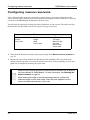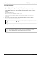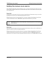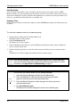
1
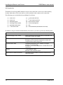
OMNI-Manure user manual 2 2002, Phason Inc. All rights reserved. Printed in Canada. 270401 Rev. 0 2002-10-25 i ii LIMITED WARRANTY Software Phason Inc. (Phason) warrants for a period of 90 days from the date of purchase that the software product will execute its programming instructions when properly installed on the personal computer or workstation indicated on this package. Phason does not warrant that the operation of the software will be uninterrupted or error-free. Should this software product fail to execute its programming instructions during the warranty period, the purchaser’s remedy shall be to return the software CD (media) to Phason for replacement. Should Phason be unable to replace the media within a reasonable amount of time, the purchaser’s alternate remedy shall be a refund of the purchase price upon return of the product and all copies. Media Phason warrants the media upon which this product is recorded to be free from defects in materials and workmanship under normal use for a period of 90 days from the date of purchase. Should the media prove to be defective during the warranty period, the purchaser’s remedy shall be to return the media to Phason for replacement. Should Phason be unable to replace the media within a reasonable amount of time, the purchaser’s alternate remedy shall be a refund of the purchase price upon return of the product and all copies. Notice of warranty claims The purchaser must notify Phason in writing of any warranty claim no later than 30 days after the warranty period expires. Limitation of warranty Phason makes no other express warranty, whether written or oral, with respect to this product. Any implied warranty of merchantability or fitness is limited to the 90 days of this written warranty. Some states or provinces do not allow limitations on how long an implied warranty lasts, so the above limitation or exclusion may not apply to you. This warranty gives specific legal rights and you may have other rights, which vary from state to state, or province to province. Exclusive remedies The remedies provided above are the purchaser’s sole and exclusive remedies. Phason shall not be liable for any direct, indirect, special, incidental, or consequential damages (including lost profit) whether based on warranty, contract, tort, or any other legal theory. Some states or provinces do not allow the exclusion or limitation of incidental or consequential damages, so the above limitation or exclusion may not apply to you. Warranty service Warranty service may be obtained from the Phason office location indicated in the user manual or service booklet. iii iv LIMITED WARRANTY This warranty applies only to the Manure Level Sensor (MLS). If you need warranty service, return the product and original proof of purchase to your dealer. Phason Inc. (Phason) warrants this product subject to the following terms and conditions. This warranty is valid only to the original purchaser of the MLS, for two years from the manufacturing date. The manufacturing date is stated in the first eight digits of the serial number in the form yearmonth-day. Phason hereby warrants that should the MLS fail because of improper workmanship, Phason will repair the MLS, effecting all necessary parts replacements without charge for either parts or labor. Conditions Installation must be done according to our enclosed installation instructions. The MLS must not have been previously altered, modified, or repaired by anyone other than Phason. The MLS must not have been involved in an accident, misused, abused, or operated or installed contrary to the instructions in our user and/or installation manuals. Phason's opinion about these items is final. The person requesting warranty service must be the original purchaser of the MLS, and provide proof of purchase upon request. All transportation charges for products submitted for warranty must be paid by the purchaser. Except to the extent prohibited by applicable law, no other warranties, whether expressed or implied, including warranties of merchantability and fitness for a particular purpose, shall apply to the MLS. Any implied warranties are excluded. Phason is not liable for consequential damages caused by the MLS. Phason does not assume or authorize any representatives, or other people, to assume any obligations or liabilities, other than those specifically stated in this warranty. Phason reserves the right to improve or alter the MLS without notice. v vi Service and technical support Your dealer will be happy to answer all technical questions that will help you use OMNI-Manure. Before contacting your dealer or Phason, check the following: Read this manual or check the online Help for information about the window you are having trouble with. If you still have a problem with OMNI-Manure or OMNI-4000, collect the following information: − − − − Any messages displayed by the OMNI-4000 software A description of the problem A description of what you were doing before the problem occurred Information about your manure storage reservoir (type and dimensions) My dealer’s name: How to contact my dealer: Street/PO Box City State/Province Zip/Postal Phone Fax E-mail Web site 2 Terracon Place Winnipeg, Manitoba Canada R2J 4G7 Phone Fax E-mail Web site 204-233-1400 204-233-3252 [email protected] www.phason.ca vii viii Table of contents Chapter 1: Introducing OMNI-Manure ............................................................................... 1 Introducing OMNI-Manure........................................................................................................................ 3 Theory of operation .............................................................................................................................. 4 Features ............................................................................................................................................... 4 About this manual..................................................................................................................................... 5 Styles used in this manual ................................................................................................................... 5 Screen terminology .............................................................................................................................. 6 Computer requirements ........................................................................................................................... 7 Chapter 2: Installing the hardware ..................................................................................... 9 Installing the hardware ........................................................................................................................... 11 Installing the Manure Level Sensor ........................................................................................................ 11 Installing a Regulated Power Supply ..................................................................................................... 19 Chapter 3: Configuring OMNI-Manure ............................................................................. 21 Installing and configuring OMNI-Manure ............................................................................................... 23 Selecting the units of measure............................................................................................................... 24 Understanding manure groups .............................................................................................................. 25 Adding, editing, and removing manure groups ..................................................................................... 27 Configuring manure reservoirs............................................................................................................... 30 Setting the manure level alarms............................................................................................................. 33 Chapter 4: Monitoring manure levels............................................................................... 35 Viewing manure levels............................................................................................................................ 37 Creating manure level charts ................................................................................................................. 39 Changing the chart options ............................................................................................................... 41 Zooming and panning........................................................................................................................ 42 Selecting a date range ....................................................................................................................... 43 Creating Manure storage reports ........................................................................................................... 44 Printing reports................................................................................................................................... 47 Interpreting data ..................................................................................................................................... 48 Understanding data accuracy............................................................................................................ 48 Maintaining data................................................................................................................................. 50 Appendixes ....................................................................................................................... 51 Appendix A: Worksheets ........................................................................................................................ 53 Manure group worksheet ................................................................................................................... 53 Manure reservoir worksheet............................................................................................................... 54 Manure level alarm settings worksheet.............................................................................................. 56 Appendix B: Troubleshooting................................................................................................................. 57 Appendix C: Hints and tips..................................................................................................................... 59 Appendix D: Glossary............................................................................................................................. 61 ix x Phason Chapter 1: Introducing OMNI-Manure This chapter introduces you to OMNI-Manure and the layout of this manual. Read this chapter before reading the rest of the manual. Introducing OMNI-Manure About this manual Screen terminology Computer requirements 2002-10-25 1 Introducing OMNI-Manure 2 OMNI-Manure user manual 270401 rev. 0 OMNI-Manure user manual Introducing OMNI-Manure Introducing OMNI-Manure All of us at Phason want to welcome you to OMNI-Manure, an easy and effective solution for monitoring manure levels at your site. OMNI-Manure works with the Manure Level Sensors to measure the manure level in your reservoirs (tanks, pits, or lagoons). The Manure Level Sensors use ultrasonic technology to accurately measure manure levels. OMNI-Manure is part of the OMNI-4000 Integrated Production Control system. Easy-to-read displays show you manure levels, manure level forecasts, and alarm levels. The charting and reporting tools allow you to review and print manure level information for any previous period. As with all OMNI-4000 software modules, you can export information to third-party software such as databases, spreadsheet programs, or reporting packages. 2002-10-25 3 Introducing OMNI-Manure OMNI-Manure user manual Theory of operation The Manure Level Sensor uses an ultrasonic transducer to sense (measure) manure levels. The sensor emits ultrasonic pulses that are reflected by the manure. The reflected pulse is called an echo. The sensor measures the time the pulses take to reflect back to the sensor and then sends the data to the OMNI-Manure software. OMNI-Manure analyzes the data and then converts it to reliable measurements of the manure level, which it displays in height or volume. OMNI-Manure determines the amount of manure accumulating over time by measuring the manure levels at different times of the day and then calculating the change. OMNI-Manure calculates the manure level at midnight each day. Features OMNI-Manure Easy-to-read manure level displays Powerful, easy-to-use charting and reporting tools Flexible information display–Imperial or metric, height or volume Programmable alarms with notification and logging Manure Level Sensor 4 Reliable, accurate ultrasonic technology Capability to monitor reservoirs up to 32 feet deep Easy-to-follow installation instructions -22 to 104°F (-30 to 40°C) operating range Weather and UV-resistant enclosures Two-year limited warranty 270401 rev. 0 OMNI-Manure user manual About this manual About this manual This manual describes the features of OMNI-Manure and how to use them. You should be familiar with the following: Microsoft Windows™ – how to perform basic Windows functions such as opening and closing windows, finding and opening files, saving and closing files, as well as using a mouse and keyboard. OMNI-4000 software – basic windows and procedures in the main OMNI-4000 software. For more information, refer to the OMNI-4000 Software User Manual. OMNI-4000 hardware and equipment – common OMNI-4000 hardware devices such as Power Blocks. Styles used in this manual This manual uses the following styles: All buttons are bolded. For example: Click OK to save the changes. All menu commands are bolded and separated by a comma. For example: On the menu bar, click File and then click Exit to close OMNI-4000. All keyboard keys are in upper case letters. Keys that need to be pressed at the same time are separated by a +, multiple steps are separated by a comma. For example: Press ALT+X or ALT+F,X to close OMNI-4000. All filenames and directories are in a monospace font. For example: The default directory is C:\OMNI4000. Hint/tip This is a hint or tip. It contains helpful information that might make it easier for you to set up or use OMNI-Manure. Note This is a note. It contains information that might help you better understand OMNI-Manure. A copy of this manual is also on your OMNI-4000 installation CD. The file is in Adobe Acrobat™ Portable Document Format (PDF). The PDF file (27040100.pdf) installs in C:\OMNI\Docs during a normal installation. You can view this file by opening it using Adobe Acrobat Reader™. 2002-10-25 5 OMNI-Manure user manual Screen terminology The following image shows the terminology this manual and Phason’s Customer Support use to describe the Microsoft Windows and the OMNI-4000 software. If you are unfamiliar with any of these terms, bookmark this page so you can refer to it. title bar Start button 6 list box Start menu window taskbar label tab check box drop-down box text box option button group box icon desktop spin box button system tray 270401 rev. 0 OMNI-Manure user manual Computer requirements Computer requirements These are the requirements for a new computer to run OMNI-Manure. The computer must meet or exceed these requirements. If you have any questions about these requirements, please contact Phason's customer service at 204-233-1400 or [email protected]. Component Requirement Notes Motherboard Pentium or equivalent - Must have at least one ISA or PCI slot for the OMNI serial port - OMNI-Alarm version 1.03 requires an ISA slot Processor (CPU) 800 MHz Memory (RAM) 128 MB PC-100 SDRAM Monitor 17" Display adapter (video card) 8 MB, 800°600 high color Hard disk 20 GB CD–ROM 40 X - A CD–R/RW is useful for backups Floppy disk drive Standard 3.5", 1.44 MB - A ZIP drive is useful for backups Keyboard Standard 104-key - Compatible with the motherboard Mouse Standard 2-button - Compatible with the motherboard Modem 56K (US Robotics) - External serial modems are recommended—do not use external USB modems - Use hardware modems that have a controller—do not use software modems or WinModems Operating system Windows 98 SE or Me Other software Symantec pcAnywhere version 10.0 or later - The video card may be on the motherboard or a separate ISA, PCI, or AGP card - 1024°768 true color is recommended - OMNI-Enterprise requires pcAnywhere 10.0 or higher If you will not be using Phason’s remote services, you will not need the modem or pcAnywhere Sound cards can cause problems with OMNI-4000 and should be avoided. The OMNI serial port must not have the same interrupt request (IRQ) as any other device. To print charts and reports, you must have a printer installed and connected to the computer. 2002-10-25 7 Computer requirements 8 OMNI-Manure user manual 270401 rev. 0 Phason Chapter 2: Installing the hardware This chapter explains how to install the Manure Level Sensors and Regulated Power Supply. Read this chapter and install all the hardware before installing and configuring the OMNI-Manure software. Installing the hardware Installing the Manure Level Sensor Installing a Regulated Power Supply 2002-10-25 9 Installing the hardware 10 OMNI-Manure user manual 270401 rev. 0 OMNI-Manure user manual Installing the hardware Installing the hardware Before you install the OMNI-Manure software and begin using the system, you must install the hardware. The hardware consists of the Manure Level Sensors and power supply (Phason Regulated Power Supply recommended). This chapter explains how to install the Manure Level Sensors and Regulated Power Supply. Read this chapter and install all the hardware before installing and configuring the OMNI-Manure software. Installing the Manure Level Sensor Phason’s Manure Level Sensor (MLS) works with OMNI-Manure to measure and monitor the manure level in a concrete manure reservoir. The Manure Level Sensor uses ultrasonic technology to accurately measure the manure levels. The sensor emits ultrasonic pulses that are reflected by the manure. The sensor measures the time the pulses take to reflect back to the sensor and then sends the data to the OMNI-Manure software. The Manure Level Sensor requires careful installation for proper long-term operation. Carefully read and follow all the instructions in the order they are listed. If you do not follow the instructions and install the Manure Level Sensor properly, the Manure Level Sensor might not operate properly. DO NOT open the sensor unit. This will damage the seal and void the warranty. Phason recommends using conduit to protect all communication and power cables. Use watertight strain reliefs or conduit connectors at all cable entry points. Make sure the communication and sensor cables do not become pinched or bent. When selecting a location for the sensor and control units, select a location where they will not be damaged when the tank is filled or pumped. MLS electrical ratings 10 to 14 VDC 125 mA 2002-10-25 11 Installing the Manure Level Sensor OMNI-Manure user manual MLS parts list The Manure Level Sensor (MLS) hardware consists of the control unit, sensor unit, and the mounting brackets and hardware. The sensor unit has a cable attached to it that connects to the control unit. The following parts are included with your Manure Level Sensor 5 (1) – control unit (1) – /8-inch strain relief nut (1) – sensor unit (1) – installation guide (1) – /16-inch masonry drill bit (8) – 2-inch masonry screws (1) – mounting bracket (base) (1) – mounting bracket (top) 5 (1) – /8-inch strain relief (7) – 1-inch mounting bolts (7) – nuts (2) – U-bolt assemblies (with washers and nuts) 3 In addition to the parts included with the Manure Level Sensor, you need to provide the following items. Item Notes DC power supply (10 to 14 VDC) - Phason Regulated Power Supply (RPS) or equivalent. For information, contact your dealer. Power cable - 20 AWG or larger, weather resistant - Enough to go from the power supply to the control unit - Longer distances require larger wire Communication cable - Unshielded twisted pair (UTP), category 3 or higher (category 5 recommended) - Enough to go from the OMNI-Server or Power Block to the control unit Conduit - /4-inch diameter, metal - Minimum 5 feet, maximum 6 feet Strain reliefs or conduit connectors - Use watertight strain reliefs or conduit connectors at all cable entry points 12 3 270401 rev. 0 OMNI-Manure user manual Installing the Manure Level Sensor MLS installation Before you install the Manure Level Sensor: Collect all the necessary items. Carefully read all the instructions. There are six main steps to installing the Manure Level Sensor. Follow all the steps in the order they are listed. 1 2 Read all the Assemble the installation mounting instructions and bracket. collect all the necessary items. 3 4 5 6 Mount the sensor and control units. Connect the Connect the sensor cable to communication the control unit. wiring to the control unit. Connect the power wires and fasten the cover to the control unit. MLS control unit layout Incoming power terminal block Connect the incoming DC power to this terminal block. Communication socket Plug the communication connecter into this socket. Communication cable Run the communication cable through this knockout. Power cable Run the incoming power cable through this knockout. Sensor cable Run the sensor cable through this knockout. Sensor terminal blocks Connect the sensor unit wires to these terminal blocks. 2002-10-25 Termination resistors If there are any devices on this communication channel after this Manure Level Sensor, then use wire cutters to remove only these two resistors. Address label This is the Manure Level Sensor's address on the OMNI-4000 system. Write down this address, the person installing the software will need it. 13 Installing the Manure Level Sensor OMNI-Manure user manual Assemble the bracket 1. Insert three of the mounting screws through the center row of holes in the bracket base. 2. Place the bracket top over the screws and then fasten it to the bottom using three of the nuts. Bracket top Bracket base (square hole this side) Mark and drill the mounting holes 1. Place the bracket on the edge of the tank. 2. Mark the four holes (shown with an ° below) for the top using a marker or punch. Be careful not to move the bracket while you are marking the holes. 3. Mark the four holes for the side. 4. Make sure all the holes line up and then remove the bracket. 5. Drill the holes using the masonry bit. Mark and drill the holes marked with an °. 14 270401 rev. 0 OMNI-Manure user manual Installing the Manure Level Sensor Fasten the control unit to the bracket 1. Insert the remaining four mounting screws through the four inside holes in the bracket base. 2. Place the control unit over the screws with the electrical knockouts facing down. 3. Fasten the control unit to the base using the remaining nuts. Control unit Electrical knockouts Fasten the bracket to the tank 1. Place the bracket over the drilled holes. Make sure all the holes line up. 2. Fasten the bracket to the tank using the masonry screws. 2002-10-25 15 Installing the Manure Level Sensor OMNI-Manure user manual Fasten the sensor to the bracket 1. Insert the U-bolts through the holes in the bracket and then attach the washers and nuts. Do not tighten the nuts at this time. 2. Run the sensor cable through a five to six foot piece of ¾-inch conduit. 3. Fasten the conduit to the conduit connector. 4. Insert the conduit through the U-bolts and then align the sensor so that the screen is pointing down. 5. Tighten the nuts on the U-bolts. The sensor screen must be pointing down at exactly a 90-degree angle or the sensor will not provide accurate readings. Top view Nut Conduit Sensor unit Washer U-bolt Side view 90° 16 270401 rev. 0 OMNI-Manure user manual Installing the Manure Level Sensor Connect the sensor cable to the control unit 1. Remove the cover from the control unit. 2. Run the cable from the conduit down to the control unit. 3. Insert the cable through the strain relief in the control unit and then tighten the strain relief nut. 4. Connect the sensor wires to their terminal blocks according their color (for example, green sensor wire to GREEN terminal block). See the drawing on page 13 for locations. DO NOT cut, splice, or add onto the sensor cable. Connect the communication cable to the control unit If you are using conduit for the communication and power cables, run all the cables in a single conduit and into the enclosure through the middle electrical knockout. If you are using strain reliefs, remove the left electrical knockout (or drill an appropriately sized hole in the knockout) and insert the communication cable into the enclosure through a watertight strain relief. See the drawing on page 13 for the location. 1. Insert the communication cable through the strain relief or conduit connector. 2. Remove the communication connector from the socket. 3. Connect the communication wires as shown at the top of the next page. 4. If the MLS is not the last device on the communication channel, use side cutters to remove the termination resistors from the circuit board. See the drawing on page 13 for the location. 5. Continue the communication wire as shown below and on the next page. For more information about communication wiring, see the OMNI-4000 Hardware Installation manual or contact your dealer. The communication cable must be connected as a continuous string from the OMNI Server to the last device on the communication channel. Do not use ‘branches’ or ‘T connections’. The drawing at the top of the next page shows examples of correct and incorrect wiring. The last device on the communication channel must have the termination resistors or a termination module installed. For more information, see the OMNI-4000 installation manual or contact your dealer. 2002-10-25 17 Installing the Manure Level Sensor Communication connector OMNI-Manure user manual Communication socket D C B A COM A B C D Correct Incorrect Communication wires Do not use excessive force when pulling the communication cable through conduit or strain reliefs. Pulling the communication cable with more than 25 pounds of force can damage the cable. Connect the control unit to the power supply If you are using strain reliefs, use the ½-inch hole in the middle electrical knockout (or drill an appropriately sized hole in the knockout) and insert the power cable into the enclosure through a watertight strain relief. See the drawing on page 13 for the location. 1. Connect the negative DC power wire to the VDC– terminal. 2. Connect the positive DC power wire to the VDC+ terminal. Phason recommends using the Phason Regulated Power Supply (RPS). The RPS is a CSA approved, Class-2 power supply. The RPS supplies 13.6 VDC and is the ideal power supply for a Manure Level Sensor. The RPS can supply power for up to eight Manure Level Sensors. For more information about the Phason RPS, contact your dealer. Fasten the cover to the control unit 1. Check to make sure you have connected all the wires to their proper locations. 2. Write down the Manure Level Sensor address (see the drawing on page 13 for the location), the person installing the software will need this information. 3. Fasten the cover to the control unit. 18 270401 rev. 0 OMNI-Manure user manual Installing a Regulated Power Supply Installing a Regulated Power Supply Phason's Regulated Power Supply (RPS) is a CSA approved, Class-2 power supply. The RPS supplies 13.6 VDC and 24 VAC power. The RPS is the ideal power supply for a Manure Level Sensor. The RPS has a battery-backup option. The battery backup supplies enough power to maintain or slowly charge a 12 V gel cell battery (not included). If the incoming AC power fails, the battery provides power to the devices connected to the DC output terminal. If you are using the battery-backup option, you must purchase the Phason battery cable assembly (part number 240012). For more information, contact your dealer. RPS electrical ratings Input 115/230 VAC 50 VA 50/60 Hz Output 24 VAC 13.6 VDC Ë 15 W maximumË Fuse 250 V 1 A, fast-acting glass Ë See NOTE below The RPS supplies a maximum of 15 W of power. This means the combined power consumption of all the devices you connect to the RPS cannot be more than 15 W. Some devices have a power consumption rating in watts; others have a current draw in amperes. To convert an ampere rating to watts, use the following formula. W=V° °A W=watts, V=volts (24 VAC or 13.6 VDC), A=amperes Before connecting multiple devices to the RPS, you need to calculate the total power consumption of all the devices. For example, you have eight Manure Level Sensors you want to connect to an RPS. A Manure Level Sensor draws 125 mA. What is the total power consumption for these devices? Using the formula W=°A, calculate the power consumption as follows: 13.6 ° .125 A=1.70 A Manure Level Sensor consumes 1.70 W of power. Calculate the total power consumption. 8 ° 1.70 W=13.6 W 2002-10-25 The total power consumption of eight Manure Level Sensors is 13.6 W. 19 Installing a Regulated Power Supply OMNI-Manure user manual RPS layout Backup-battery terminal 13.6 VDC output terminal - use for MLS voltage selector switch 115 or 230 VAC Electrical knockouts Incoming-power terminal Fuse 250 V 1A, non time-delay If you are not using the backup-battery terminal with a backup battery, you can use it as another 13.6 VDC output terminal. The RPS has a resettable fuse that protects the unit against a severe overload. A severe overload of the AC output will trip the fuse. To reset the fuse, follow the steps below. 1. Disconnect the incoming power or the AC load. 2. Fix the problem that caused the overload. 3. Reconnect the power or the AC load. RPS installation Use the electrical knockouts to run the wires into the enclosure. 1. Remove the electrical knockouts from the enclosure. 2. Mount the RPS on a vertical surface with the electrical knockouts facing down. 3. Set the voltage selector switch to the correct incoming power. It is set at the factory for 230 VAC. 4. Connect the incoming power wires to the incoming power terminal. 5. Connect the devices to the output terminals. Connecting the output terminals together will destroy the power supply and void the warranty. 20 270401 rev. 0 Phason Chapter 3: Configuring OMNI-Manure This chapter explains how to install and configure OMNI-Manure. Installing and configuring OMNI-Manure Selecting units of measure Adding, editing, and removing manure groups Configuring manure reservoirs Configuring manure level alarms 2002-10-25 21 Installing and configuring OMNI-Manure 22 OMNI-Manure user manual 270401 rev. 0 OMNI-Manure user manual Installing and configuring OMNI-Manure Installing and configuring OMNI-Manure OMNI-4000 has an Installation Wizard that guides you through the installation. Make sure you have all the hardware installed before installing OMNI-Manure. For more information, see Chapter 2: Installing the hardware on page 9. To install OMNI-Manure 1. Insert your OMNI CD into you computer’s CD-ROM drive. The Installation Wizard should start automatically. If it does not start automatically, find and start the file Autorun.exe on the CD-ROM. 2. Follow the instructions on the screen. After installing the hardware and software, you need to configure the software to work with the hardware and to display and monitor data the way you want. Configuring OMNI-Manure involves several tasks: Selecting units of measure Creating manure groups Measuring and configuring manure storage reservoirs Configuring manure level alarms Use the worksheets in Appendix A to help you configure OMNI-Manure. 2002-10-25 23 Selecting the units of measure OMNI-Manure user manual Selecting the units of measure The first options you need to configure are the units of measure for distance and liquid volume. OMNI-Manure uses these options when it displays data. The units of measure you select for distance and liquid volume affect other OMNI-4000 modules. For example, if you change the unit of measure for liquid volume, it will also affect OMNI-Water. Select standard units of measure for all modules. The Configuration Manager allows you to select the units of measure for distance and liquid volume. The Options tab is shown below. To select the units of measure 1. Open the Configuration Manager and then click the Options tab. 2. In the Distance group box, click the option button beside the unit of measure you want to use. 3. In the Liquid Volume group box, click the option button beside the unit of measure you want to use. 24 270401 rev. 0 OMNI-Manure user manual Understanding manure groups Understanding manure groups After you select the units of measure, you need to add manure groups. A manure group is the OMNI-Manure term for a manure storage reservoir (tank, pit, or lagoon) that is monitored by a Manure Level Sensor. The following image explains the relationships between the site, buildings, and groups. Site Phason Farms Building Barn 1 Group Feed Ventilation Water Equipment Feed Sensor Mister Heater Fan Lights Actuator Water Meter Site The site includes all the barns at your site that are controlled by the OMNI-4000. Building A building is a single barn at your site. A building consists of one or more groups. Group There are four types of groups in OMNI-4000: ventilation groups, feed groups, water groups, and manure groups. A manure group is the manure storage reservoir (tank, pit, or lagoon) for which the Manure Level Sensor measures the manure level. A manure group also contains all the settings and configuration for the Manure Level Sensor and reservoir it represents. For information about ventilation, feed, or water groups, see the OMNI-4000 user manual, OMNI-Feed user manual, and OMNI-Water user manual. Equipment The equipment is items that are connected to a Power Block or OMNI-Server. Equipment includes fans, heaters, feed augers, water meters, etc. In OMNI-Manure, the equipment is the Manure Level Sensor that monitors the manure level in a reservoir. 2002-10-25 25 Understanding manure groups OMNI-Manure user manual The following images show two ways of configuring manure groups at your site. Method 1 has one deep under-slat storage pit per barn. For this method, create one manure group for each building. Method 1—Deep under-slat storage pits, one pit per barn Site Phason Farms Barn 1 Barn 2 Barn 3 Manure Group 1 Manure Group 2 Manure Group 3 Building Group Method 2 has shallow under-slat storage pits in each barn and pumps them into an aboveground tank or lagoon. The Manure Level Sensor monitors the level in the aboveground tank or lagoon. For this method: 1. Create an ‘imaginary’ building and name it ‘manure tank’. 2. Create a manure group for the manure tank building. Method 2—Shallow under-slat storage pits, pumped into a lagoon or aboveground tank Site Phason Farms Manure Tank Building Barn 1 Barn 2 Barn 3 Manure Group 26 Group 270401 rev. 0 OMNI-Manure user manual Adding, editing, and removing manure groups Adding, editing, and removing manure groups After you install OMNI-Manure and select the units of measure, you need to add manure groups. If you add a Manure Level Sensor to a reservoir, you need to add a new manure group to OMNI-Manure. If you replace a Manure Level Sensor, you may need to edit the manure group. The Configuration Manager allows you to add, edit, or remove manure groups. The Manure tab is shown below. B A C D E F A B C D This is a list of buildings at your site. This is a list of manure groups in the selected building. This is the Manure Level Sensor address for the selected manure group. These two buttons open the Manure Group Description window, which allows you to add or edit a manure group. E This button allows you to remove a manure group. F This button opens the Manure Reservoir Configuration window, which is where you enter the dimensions for a reservoir. For more information, see Configuring manure reservoirs on page 30. Use the Manure group worksheet on page 53 to help you configure the manure groups. 2002-10-25 27 Adding, editing, and removing manure groups OMNI-Man To add a manure group 1. Open the Configuration Manager and then click the Manure tab. 2. Click Add Manure Group. The Manure Group Description window appears. 3. In the Building list box, select the building containing the manure storage reservoir for which you want to create the manure group. 4. In the Group Name text box, enter a name for the manure group. 5. In the Manure Sensor list box, select the address of the Manure Level Sensor that will be monitoring the manure storage reservoir. If there are no Manure Level Sensor addresses listed, make sure the Manure Level Sensors are properly connected to the OMNI-4000 system. For more information, see Installing the Manure Level Sensor on page 11. 6. Click OK to save the manure group and return to the Manure tab. To edit a manure group 1. Open the Configuration Manager and then click the Manure tab 2. In the Buildings list box, select the building containing the manure group you want to edit. 3. Click Edit Manure Group. The Manure Group Description window appears. 4. Make the changes to the manure group. 5. Click OK to save the changes and return to the Manure tab. 28 270401 rev. 0 OMNI-Manure user manual Adding, editing, and removing manure groups To remove a manure group 1. Open the Configuration Manager and then select the Manure tab 2. In the Buildings list box, select the building containing the manure group you want to remove. 3. From the Manure Groups list, select the manure group you want to remove and then click Remove Manure Group. A confirmation window appears. 4. To remove the manure group, click Yes. To cancel and return to the Manure tab, click No. When you remove a manure group from the Configuration Manager, you also remove it from the Settings Manager. OMNI-Manure will no longer collect data for that group. The manure group does not disappear from the reports and viewers lists until all the manure data for that group is archived. Until then you can create reports and charts with the existing manure data for that group. 2002-10-25 29 Configuring manure reservoirs OMNI-Manure user manual Configuring manure reservoirs After selecting the units of measure and creating a manure group, you need to configure the manure storage reservoir. Since a Manure Level Sensor measures the height and volume of manure in a reservoir, you need to tell OMNI-Manure the dimensions of the reservoir. You will need the engineering drawings that list the dimensions of your reservoir. The table below lists the dimensions (measurements) you need to enter for each type of reservoir. Tank Pit Lagoon Height Diameter Sensor offset Height Length Width Sensor offset Height Top length Bottom Length Top width Bottom width Sensor offset Write down the dimensions from the engineering drawings in the Manure reservoir worksheet on page 54. Measure the sensor offset and then enter the distance in the worksheet. The sensor offset is the distance from the top of the reservoir to the bottom of the sensor. A long straightedge or level and a plumb line are helpful for measuring the sensor offset. Make sure you measure and enter the dimensions in the same unit of measure you have selected for OMNI-Manure. For more information, see Selecting the units of measure on page 24. When entering the height of the manure storage reservoir, subtract the freeboard height from the total height. Check the local regulations for the amount of freeboard necessary in your area. 30 270401 rev. 0 OMNI-Manure user manual Configuring manure reservoirs After writing down the dimensions in the Manure reservoir worksheet, you need to enter the information into OMNI-Manure. OMNI-Manure uses these dimensions when it calculates the amount of manure in a reservoir. The Manure Reservoir Configuration window is where you enter the dimensions for a manure storage reservoir. The Manure Reservoir Configuration window is shown below. A B C D E A This is the manure group you selected in the Manure tab. B These option buttons allow you to select the type of reservoir. C This is the unit of measure OMNI-4000 is configured for. You must enter the dimensions in the same unit of measure. For more information, see Selecting the units of measure on page 24. D These spin boxes allow you to change the dimensions and sensor offset. E This is an image of the reservoir (pit, tank, or lagoon). The image changes when you change the reservoir type. Use the Manure reservoir worksheet on page 54 to help you configure the manure storage. 2002-10-25 31 Configuring manure reservoirs OMNI-Manure user manual To configure a reservoir 1. Open the Configuration Manager and then click the Manure tab. 2. From the Buildings list box, select the building containing the reservoir you want to configure. 3. From the Manure Groups list box, select the manure group representing the reservoir you want to configure. 4. Click Configure Reservoir. The Manure Reservoir Configuration window appears. 5. In the Reservoir Type group box, click the option button beside the type of reservoir you are configuring. 6. Place the cursor in one of the spin boxes, delete the existing number, and then enter the new dimension. Repeat this step for each dimension. You can also use the dimensions. or buttons on the spin boxes to adjust the reservoir 7. Click OK to save the configuration and return to the Manure tab. After entering the dimensions, make sure you have entered them correctly. Incorrect dimensions will affect the manure level measurements. 32 270401 rev. 0 OMNI-Manure user manual Setting the manure level alarms Setting the manure level alarms After configuring the manure groups and manure storage, you can set the manure level alarms. You can have the same or different alarm levels for each manure group. There are two manure level alarms: pump level and alarm level. Pump Level The pump level is the manure level in feet or metres from the bottom of the manure storage reservoir. Set the pump level at the level you would usually pump out the reservoir. When the manure level rises above the pump level, a message is displayed in the Manure Level Viewer and the Communication Center. OMNI-Manure updates this information every two hours. OMNI-Manure does not control the pump; it only warns you that it is time to pump out the reservoir. Alarm Level The Alarm level is the manure level (in feet or metres from the bottom of the reservoir) at which there is a danger of overflow and you need to pump immediately. When the manure level rises above the alarm level, a message is displayed in the Manure Level Viewer and the Communication Center and an entry is recorded in the alarm log. OMNI-Manure updates this information every two hours. For more information about the alarm log, see the OMNI-4000 user manual. 2002-10-25 33 Setting the manure level alarms OMNI-Manure user manual To configure the manure level alarms 1. Open the Settings Manager and then click the Manure tab. 2. From the Buildings list box, select the building containing the manure group you want to configure. 3. From the Manure Groups list box, select the manure group you want to configure and then click Set up Manure Alarms. The Manure Group Settings window appears. 4. In the Pump Level text box, enter the pump level. Make sure you enter the distance in the same unit of measure that you have selected for OMNI-Manure. 5. In the Alarm Level text box, enter the alarm level. Make sure you enter the distance in the same unit of measure that you have selected for OMNI-Manure. 6. To enable the alarms, click the Enable Alarms check box. A check mark appears in the box if the alarms are enabled. 7. Click OK to save the settings and return to the Manure tab. 34 270401 rev. 0 Phason Chapter 4: Monitoring manure levels This chapter explains how to monitor and analyze the data that OMNI-Manure collects. Viewing manure levels Creating manure level charts Creating manure level reports Interpreting data 2002-10-25 35 Viewing manure levels 36 OMNI-Manure user manual 270401 rev. 0 OMNI-Manure user manual Viewing manure levels Viewing manure levels The Manure Level Viewer displays information about the manure level in a manure storage reservoir. The yellow area is the manure level, the blue arrow is the pump level, and the red arrow is the alarm level. The boxes on the right display information about the manure level. The Pump indicator changes to blue when the manure level is above the pump level. The Alarm indicator changes to red when the manure level is above the alarm level. For more information about alarm level settings, see Setting the manure level alarms on page 33. A B D C A B C D E E This drop-down box contains a list of buildings at your site. This drop-down box contains a list of manure groups in the selected building. This is an image of the manure reservoir represented by the group. The first two boxes are the pump and alarm level indicators. The next five boxes contain information about the amount of manure in the reservoir. Height Remaining Height remaining is the height from the top of the manure to the top of the reservoir. Current Volume Current volume is the amount of manure in the reservoir. OMNI-Manure calculates the volume using the manure level and the dimensions of the reservoir. Capacity Capacity is the volume of manure that can be stored in the reservoir. OMNI-Manure calculates the capacity using the dimensions of the reservoir. 2002-10-25 37 Viewing manure levels OMNI-Manure user manual Days Remaining Days remaining is the number of days remaining before the manure level reaches capacity. OMNIManure calculates the days remaining using the capacity of the reservoir and the average increase in the manure level during the last 30 days. Because this information is an estimate based on past manure level increases, you should use this information as a guideline only. Readings Taken Readings taken is the date and time the reading was taken. OMNI-Manure updates the information every two hours. To view the manure level for a manure group 1. Open the Reports Utility and then click the Manure tab. The Manure Reports Utility appears. 2. Click View Manure Level. The Manure Level Viewer appears. 3. From the Building drop-down box, select the building containing the manure group for which you want to view the manure level. 4. From the Group drop-down box, select the manure group for which you want to view the manure level. The Manure Level Viewer displays the information for the manure group. If you see the message “Unable to determine manure level” in the bottom-right corner of the viewer, there is a problem with the Manure Level Sensor. For more information, see Appendix B: Troubleshooting on page 57 You can also view manure levels from the Settings Manager 1. Open the Settings Manager and then click the Manure tab. 2. From the Buildings list, select the building containing the manure group for which you want to view the manure level. 3. From the Manure Groups list, select the group for which you want to view the manure level. 4. Click View Manure Levels. The Manure Level Viewer displays the level for the selected group. 38 270401 rev. 0 OMNI-Manure user manual Creating manure level charts Creating manure level charts You can create charts that display the manure level for a manure group. The chart displays the manure level for each selected day and the capacity of the reservoir. OMNI-Manure displays manure level charts as either bar or line charts. Line charts are a better representation of the manure level and capacity is always a line and cannot be changed. The Manure Level Chart is shown below. A B C D E A This is a list of manure groups at your site. The list is sorted by building. B These drop-down boxes allow you to change the start and end dates. C This button opens the Manure Chart Options window, which is where you change the display options for the chart. D These option buttons allow you to choose the type of chart. E These option buttons allow you to select whether you want to display the chart as manure height or volume. 2002-10-25 39 Creating manure level charts OMNI-Manure user manual To create a manure level chart 1. Open the Reports Utility and then click the Manure tab. 2. Click Manure Chart. The Manure Chart window appears. 3. From the Manure Groups list box, select the manure group for which you want to create the chart. Click the + to the left of a building to show the list of manure groups in that building. 4. Select the type of chart you want to create: To select a bar chart, click the Bar option button. To select a line chart, click the Line option button. 5. Select a date range for the chart. For more information, see Selecting a date range on page 43. The Manure Chart window displays your chart. 6. To print your chart, click Print. In the Settings Manager, you can automatically create a manure level chart containing the last 30 days of manure data. 1. Open the Settings Manager and then click the Manure tab. 2. From the Buildings list, select the building containing the manure group for which you want to create the chart. 3. From the Manure Groups list, select the group for which you want to create the chart. 4. Click View Chart. 40 270401 rev. 0 OMNI-Manure user manual Creating manure level charts Changing the chart options You can display either a bar chart or a line chart. Line charts are a better representation of the manure level. The capacity is always a line and cannot be changed. When you open the Manure Level Chart window, the chart and options displayed are the ones that were last selected. The options include: Bar chart Color—16 to choose from Border—Visible/not visible Line chart Color—16 to choose from Line width—1 to 5 Printer Page orientation—portrait or landscape To change the chart options 1. Click Options. The Manure Chart Options window appears. 2. Make the changes: To change the line color, click on the Line Color drop-down box and then select a color. To change the line width, click or on the Line Width spin box. To change the bar color, click on the Bar Color drop-down box and then select a color. To change the bar border, click the Visible check box. To change the printer page orientation, click the option button beside the page orientation you want to use. 3. Click Done. 2002-10-25 41 Creating manure level charts OMNI-Manure user manual Zooming and panning You can zoom in on (magnify) or pan (scroll along) a chart. This is useful if you have a chart that covers a large date range and you want to zoom in on a specific day or small date range. To zoom in on a chart 1. Click and drag to select the area you want to magnify. 2. Release the mouse button. The chart magnifies the area you selected. To zoom out from the chart Click on the chart and drag to the top-right and then release the mouse button. The chart returns to normal magnification. To pan a chart Right-click the chart and drag the mouse in the direction you want the chart to move. You can make the chart bigger by left-clicking the bottom-right corner of the window and dragging. 42 270401 rev. 0 OMNI-Manure user manual Creating manure level charts Selecting a date range OMNI-Manure charts and reports have an easy way to select a date range for the manure level data you want to display. A date range consists of a start date and an end date. The end date cannot be before the start date. To select a date range on the Start Date drop-down box. 1. Click The calendar appears. 2. Select a start date: To move forward and backward through the months, click or . To select a specific month, click the month on the calendar and then select the month you want to go to. To move forward and backward through the years, click the year on the calendar and then click or . 3. Click anywhere on the desktop to return to the chart or the report. 4. Click on the End Date drop-down box. 5. Select an end date. 2002-10-25 43 Creating Manure storage reports OMNI-Manure user manual Creating Manure storage reports Reports give you exact data for the period of time you choose. OMNI-Manure has a report that shows the expected full date, the fill rate, the volume, and the height of the manure in the reservoir. Below is a sample of the Manure storage report. You can create manure reports in two different formats: HTML and comma separated value. HTML reports Choose HTML (Hypertext Markup Language) if you want a report you can view and print. You can view and print HTML reports using your web browser. For examples of HTML reports, see below and Printing report on page 47. Comma separated value files Choose comma separated value (CSV) if you want to export the manure data to another program such as a spreadsheet program or reporting package. If you only want to view or print a report, choose HTML. A CSV file is a file that consists of data fields separated by commas. CSV files allow different databases to communicate (‘talk’) to each other. For information about CSV files, see the user manual for the program you want to import the CSV file into. 44 270401 rev. 0 OMNI-Manure user manual Creating Manure storage reports The Manure Reports Utility allows you to create manure level reports. The Manure Reports Utility is shown below. A B D E A B C D This is a list of manure groups at your site. The list is sorted by building. These drop-down boxes allow you to change the start and end dates for the report. These option buttons allow you to select the type of output for the report. This button creates the report. 2002-10-25 45 Creating Manure storage reports OMNI-Manure user manual To create a report 1. Open the Reports Utility and then click the Manure tab. 2. Click Manure Report. The Manure Reports Utility appears. 3. From the Group Selection list box, select the manure groups you want in the report. Click the + to the left of a building to show the list of manure groups. 4. Select the type of report output: To select an HTML report, click the HTML option button. To select a comma separated value file, click the Comma Separated (CSV) option button. 5. Select a date range for the report. For more information, see Selecting a date range on page 43. 6. Click Create. The Save As window appears. 7. In the File name text box, enter a name for the file and then click Save. OMNI-Manure displays your report. The default directory for reports is C:\omni4000\reports\. OMNI-Manure will save your report in this directory unless you choose a different one. HTML files open in your web browser. You can view your saved HTML reports anytime by opening them using you web browser. CSV files open in a text editor, spreadsheet, or similar program. 46 270401 rev. 0 OMNI-Manure user manual Creating Manure storage reports Printing reports You can view and print HTML reports using your web browser. The image below shows a sample of an HTML report in Microsoft’s Internet Explorer™. CSV files should be imported into a program such as a spreadsheet or reporting program. They are not meant to be printed in their standard format. For information about CSV files, see the user manual for the program into which you want to import the file. To print your report 1. Open the HTML report using your web browser. 2. On the menu bar, click File and then click Print. 2002-10-25 47 Interpreting data OMNI-Manure user manual Interpreting data We said earlier in the manual that OMNI-Manure charts and reports allow you to monitor manure levels at your site. OMNI-Manure charts and reports can also help you determine if you have leaks, OMNI communication problems, and many other irregularities. For example, In an OMNI-Manure report, if a day shows a level of ‘--’, then there was no reading for that day. This is not the same as a level of ‘0’. A ‘--’ reading means that there was no communication between the OMNI-4000 system and the Manure Level Sensor. This can be because the OMNI-4000 had a communication problem, or the computer was not on to collect data. A ‘0’ reading means that there was no manure in the storage reservoir that day. If you see an irregularity in a manure report or chart, try to determine what may have caused the irregularity. OMNI-Manure collects and displays manure level data, it’s up to you to add intelligence to the data and use it to your advantage. Understanding data accuracy There are two main things that affect the accuracy of the data displayed: the amount of data collected and the reservoir dimensions. Amount of data collected OMNI-Manure needs to collect data to calculate manure levels and other information for the charts, reports, and viewer. If the computer is not on and OMNI-Manure is not running, or there is a communication problem (see troubleshooting), then OMNI-Manure cannot collect accurate data. The table on the next page shows the amount of data required for the viewer, chart, and report. 48 270401 rev. 0 OMNI-Manure user manual Interpreting data Type of report Type of data Amount required Manure level viewer Height remaining Days remaining Two hours Three days* Manure level chart Height One day Manure storage report Expected full date Fill rate Height/volume Three days* Three days* One day * OMNI-Manure calculates the days remaining, expected full date, and fill rate using the capacity of the reservoir and the average increase in the manure level during the last 30 days. Three days is the minimum amount of data needed to calculate the information, but accuracy increases when more data is available. Reservoir dimensions Reservoir dimensions affect the accuracy of all the information OMNI-Manure displays. OMNI-Manure uses these dimensions to calculate the amount of manure in the reservoir. If the dimensions are in the wrong unit of measure or are not correct, the data displayed will not be correct. For more information, see Configuring manure reservoirs on page 30. 2002-10-25 49 Interpreting data OMNI-Manure user manual Maintaining data OMNI-Manure writes its information (data) to your computer’s hard disk. To make sure you do not lose any data if you have computer problems, you need to regularly back up your data. The OMNI-4000 Backup and Restore utility allows you to back up your OMNI-4000 system configuration and settings information. You can use the utility to restore your configuration and settings if your computer crashes or your database becomes corrupts. The utility does not back up historical records (such as the alarm log) maintained by the OMNI-4000. The information stored in the backups fits on a single 1.44 MB floppy diskette or can be e-mailed elsewhere for offsite storage. If you are backing up your complete hard drive on a regular basis, you may not need to run this utility. A complete hard drive backup preserves not only settings and configuration information, but historical records as well. Back up your system settings and configuration information at least once per week. Store your backups off-site in a safe place where you can easily access them. For more information about backing up and restoring data, see the OMNI-4000 user manual. 50 270401 rev. 0 Phason Appendixes Appendix A: Worksheets Appendix B: Troubleshooting Appendix C: Hints and tips Appendix D: Glossary 2002-10-25 51 Appendix A: Worksheets 52 OMNI-Manure user manual 270401 rev. 0 OMNI-Manure user manual Appendix A: Worksheets Appendix A: Worksheets This appendix contains worksheets to help you set up OMNI-Manure. Manure group worksheet Use the Manure group worksheet to help you configure the feed groups. The first line is an example of how to fill in the worksheet. For more information about configuring manure groups, see Understanding manure groups on page 25. Building Manure group Storage type MLS address (tank/pit/lagoon) Manure tank 2002-10-25 North manure reservoir Tank 00000035 53 Appendix A: Worksheets OMNI-Manure user manual Manure reservoir worksheet Enter the manure storage dimensions in the worksheets on the next page. Use the information in the worksheet when you configure the manure storage in OMNI-Manure. The first entry is an example of how to fill in the worksheet When you enter the dimensions in the software, you need to enter them as either feet or metres (depending on what you have selected in the Options tab of the Configuration Manager). If your measurements contain inches or centimetres (for example one foot, six inches), you will need to convert them to feet or metres. For example, if the diameter is 50 feet 9 inches, then you would enter 50.75 in the Manure Reservoir Configuration window (9 ÷ 12=0.75). For more information, see Configuring manure reservoirs on page 30. The chart below shows some common conversions for inches to feet and centimetres to metres. Inches Feet Centimetres Metres 1 2 3 4 5 6 7 8 9 10 11 12 0.08 0.17 0.25 0.33 0.42 0.50 0.58 0.67 0.75 0.83 0.92 1.00 10 0.10 20 30 40 50 60 70 80 90 100 0.20 0.30 0.40 0.50 0.60 0.70 0.80 0.90 1.00 Make sure you measure and enter the dimensions in the same unit of measure you have selected for OMNI-Manure. For more information, see Selecting the units of measure on page 24. When entering the height of the manure storage reservoir, subtract the freeboard height from the total height. Check the local regulations for the amount of freeboard necessary in your area. 54 270401 rev. 0 OMNI-Manure user manual Appendix A: Worksheets Manure tank North manure reservoir Sensor offset Manure group Diameter Building Height Tank dimensions (feet/metres) 19 ft. 165 ft. 0.25 ft. Building Manure group Height Length Width Sensor offset Pit dimensions (feet/metres) NW finisher Finisher reservoir 8 ft. 150 ft. 48 ft. 0.5 ft. Building Manure group Height Top length Bottom length Top width Bottom width Sensor offset Lagoon dimensions (feet/metres) Manure Reservoir Manure reservoir 20 ft. 200 ft. 180 ft. 150 ft. 135 ft. 4 ft. 2002-10-25 55 OMNI-Manure user manual Manure level alarm settings worksheet Use the worksheet to list the alarm settings for each manure group. Use the information in the worksheet when you configure the alarms in OMNI-Manure. The first entry is an example of how to fill in the worksheet Pump Level This is the manure level in feet or metres from the bottom of the manure storage reservoir. When the manure reaches the pump level, it is time to pump. Set the pump level at the level you would usually pump the manure. When the manure level rises above the pump level, a message is displayed in the Manure Level Viewer and the Communication Center. Alarm Level This is the manure level (in feet or metres from the bottom of the reservoir) at which there is a danger of overflow and you need to pump immediately. For more information about configuring manure level alarms, see Setting the manure level alarms on page 33. Building Manure tank 56 Manure group North manure reservoir Reservoir type Pump level Alarm level (tank/pit/lagoon) (feet/metres) (feet/metres) Tank 13 ft. 17 ft. 270401 rev. 0 OMNI-Manure user manual Appendix B: Troubleshooting Appendix B: Troubleshooting If you are having problems using OMNI-Manure, look up the problem in the table below and then follow the instructions to resolve the problem. If you have a problem that is not listed here, try to determine what might be causing the problem. If you cannot resolve the problem, call your dealer or Phason’s customer support (see Service and technical support.) Problem Possible cause Possible resolution “Unable to determine level” in Manure Level Viewer or the manure level displays as ‘--’ in a chart or report OMNI-Manure is not receiving data from the Manure Level Sensor Make sure the sensor is properly wired, including the communication wiring. For more information, see Installing the Manure Level Sensor on page 11. Inaccurate manure level measurements or data missing on the viewer, chart, or report. Incorrect reservoir dimensions Make sure the reservoir dimensions are correct. For more information, see Configuring manure reservoirs on page 30. Not enough data Let OMNI-Manure collect more data before creating the chart or report. For more information, see Understanding data accuracy on page 48. OMNI-Manure cannot detect the Manure Level Sensor Make sure the sensor is properly wired, including the communication wiring. For more information, see Installing the Manure Level Sensor on page 11. The Manure Level Sensor address does not appear in the Manure Group Description window. 2002-10-25 57 Appendix C: Hints and tips 58 OMNI-Manure user manual 270401 rev. 0 OMNI-Manure user manual Appendix C: Hints and tips Appendix C: Hints and tips Use the worksheets in Appendix A to help you configure OMNI-Manure. When entering the reservoir dimensions, make sure you enter them correctly and in the same unit of measure you have selected for OMNI-Manure. Inaccurate measurements affect manure level measurements. Inspect the sensor face every three months. Use a soft brush to gently remove any dirt from the screen. Do not use sharp tools, wire brushes, or compressed air to clean the sensor face. These will damage the sensor and void the warranty. 2002-10-25 59 Appendix D: Glossary 60 OMNI-Manure user manual 270401 rev. 0 OMNI-Manure user manual Appendix D: Glossary Appendix D: Glossary AC Alternating current Alarm level This is the manure level (in feet or metres from the bottom of the reservoir) at which there is a danger of overflow and you need to pump immediately. CSV Comma separated value. A file type consisting of data fields separated by commas. CSV files allow different databases to communicate (‘talk’) to each other. DC Direct current Freeboard The reserve volume in a manure storage reservoir that minimizes the chance of the contents overflowing and causing contamination. Freeboard is usually enough capacity to hold the water entering the reservoir from the highest intensity 24-hour rainfall expected to occur within 25 years. See the local regulations for your area. Do not include the freeboard level in your height measurement for the reservoir. Height remaining The height from the top of the manure to the top of the reservoir. HTML Hypertext markup language. The language used to make information viewable by a web browser. Manure group The reservoir for which the Manure Level Sensor measures manure levels. A manure group also contains all the settings and configuration for the Manure Level Sensor and reservoir it represents. Manure storage reservoir The place where your site stores the animal waste. OMNI-Manure has three types of reservoirs: aboveground tanks, pits (under-slat storage), and earthen lagoons. Pump level This is the manure level in feet or metres from the bottom of the manure storage reservoir. When the manure reaches the pump level, it is time to pump. VAC Volts of alternating current VDC Volts of direct current Reservoir See manure storage reservoir 2002-10-25 61 Appendix D: Glossary 62 OMNI-Manure user manual 270401 rev. 0 Index A H alarms hardware. See Manure Level Sensor; Regulated Power Supply alarm level, 33, 56 configuring, 33–34 displayed. See data, viewing pump level, 33, 56 worksheet, 56 L lagoons. See reservoirs liquid volume. See units of measure C M charts manure charts. See charts color. See charts, options manure data. See data creating, 39–40 date ranges, 43 manure groups adding, 27–28 options, 41 description, 25–26 panning, 42 editing, 28 printing, 40 removing, 29 scrolling, 42 understanding, 25–26 type, 41 worksheet, 53 viewing, 39–40 zooming in on, 42 Manure Level Sensor. See also OMNI-Manure electrical ratings, 11 comma separated value. See reports, CSV features, 4 computer requirements, 7 installing, 11–18 configuring. See OMNI-Manure, configuring power supply, 12 CSV. See reports, CSV manure levels. See data, viewing manure reports. See reports D data accuracy, 48 interpreting, 48–49 maintaining, 50 viewing, 37–38. See also charts; reports date ranges, 43 dimensions. See units of measure; reservoirs, configuring manure reservoirs. See reservoirs MLS. See Manure Level Sensor monitoring manure levels. See data, viewing O OMNI-Manure computer requirements, 7 configuring, 23–34 manure alarms, 33–34 E manure groups, 27–28 end dates. See date ranges resevoirs, 30–32 units of measure, 24 G features, 4 groups. See manure groups 2002-10-25 63 HTML, 44, 46 OMNI-Manure (continued) hardware. See Manure Level Sensor, installing printing, 47 hints and tips, 59 viewing, 44–46 installing, 23 introduction, 3–4 reservoirs configuring, 30–32 types, 44 screen terminology, 6 theory of operation, 4 troubleshooting, 57 worksheets, 53–56 RPS. See Regulated Power Supply S screen terminology, 6 P pits. See reservoirs power supply. See Regulated Power Supply pump level. See alarms, pump level start dates. See date ranges storage. See reservoirs T tanks. See reservoirs R Regulated Power Supply electrical ratings, 19 installing, 19–20 reports creating, 44–46 64 worksheet, 54–55 terms. See screen terminology troubleshooting, 57 U units of measure, 24 CSV, 44, 46 W formats, 44 windows terminology. See screen terminology 270401 rev. 0