1
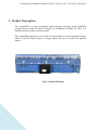
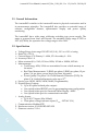
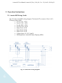
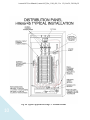
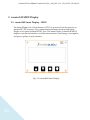
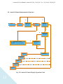
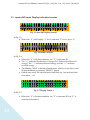
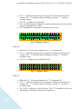
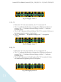
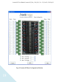
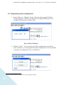
i-meter®45 Specification and User Guide
i-meter®45 User Manual (i-meter®45_Doc_1148_001, Ver. 1.2), Oct 24, 2014 by JL
i-meter®45
CONTENTS
1.
2.
Product Description.................................................................................................................. 3
1.1.
General Information .......................................................................................................... 5
1.2.
Specification ........................................................................................................................ 5
Operation Instructions ............................................................................................................. 6
2.1.
3.
i-meter®45 MDU Display ...................................................................................................... 11
3.1.
3.2.
1.1.
2.
3.
2
i-meter®45 Wiring Guide ................................................................................................. 6
i-meter®45 Smart Display – MDU ................................................................................. 11
i-meter®45 Smart Display operation flow chart ............................................................. 12
i-meter®45 Smart Display individual screens .............................................................13
i-meter®45 Programming Software ...................................................................................... 18
2.1.
Creating a configuration file ........................................................................................... 18
2.2.
Programming meter configuration................................................................................ 21
2.3.
Introduction ...................................................................................................................... 23
2.4.
Electrical connection ........................................................................................................ 24
2.5.
Register Mapping .............................................................................................................24
Appendix 1 -- Optional Pulse Output Board .....................................................................29
i-meter®45 User Manual (i-meter®45_Doc_1148_001, Ver. 1.2), Oct 24, 2014 by JL
1. Product Description
The i-meter®45 is a next generation multi-customer metering system (MCMS)
product based on MP-636 series of meters, by Intellimeter Canada Inc. (ICI). It is
installed directly inside an electric panel.
The i-meter®45 represents a new level of functionality in revenue grade electricity
meters. It has 45 current inputs, 3 voltage inputs, and up to a total of 45 separate
meters.
Fig. 1-1 i-meter®45 meter
3
i-meter®45 User Manual (i-meter®45_Doc_1148_001, Ver. 1.2), Oct 24, 2014 by JL
Fig. 1-2 i-meter®45 21_CT board
Fig. 1-3 i-meter®45 Smart Display – MDU
4
i-meter®45 User Manual (i-meter®45_Doc_1148_001, Ver. 1.2), Oct 24, 2014 by JL
1.1. General Information
The i-meter®45 is similar to the i-meter®636 meter in physical construction and in
its measurement principles. The i-meter®45 also provides an extended range of
software configurable features, alphanumeric display and power quality
monitoring.
The i-meter®45 has a wide range solid-state switching type power supply. The
meter is powered from Line1 and Neutral. The standard voltage range is 120V to
347V (60/50Hz), the operation low voltage range is 69 to 380V.
1.2. Specification
a.
b.
c.
d.
e.
f.
g.
h.
i.
j.
k.
l.
5
Voltage Range: Auto range 120-347VAC (L-N), -20% to +10% of rating
Rated VA: <12VA
Current Range: CTs Primary 0 – 600A, CTs Secondary 0 – 0.1A
Accuracy Class: 1.0
Meter constant (K h ): 1Wh, 1VAh or 10Wh, 10VAh or 100Wh, 100VAh
Measurements:
• Total Energy: kWh, kVAh are accumulated in non-volatile memory on
the meter
• Real Time Measurements: V (RMS) per phase, I (RMS) per phase, W per
phase, VA per phase, power factor per phase, frequency
• Power Quality: Per phase V & I Total harmonic Distortion (THD), Per
phase V & I individual harmonic order up to 12th
Service type: 1Φ2W, 1Φ3W, 2Φ3W, 3Φ4W (Programmable)
Digital Inputs/Outputs:
• Up to 45 optical isolated pulse outputs
• One optical isolated RS232C port for programming meter configuration
• One optical isolate port for i-meter®45 Smart Display – MDU
• One optical isolate port for communication module
Analog Inputs:
• Up to 45 CT inputs (Max 100mA)
• Three phase voltage reference inputs (V max : 347VAC L-N)
Communication: Modbus RTU
Hardware version: 101-01282 BD. REV-DE
Firmware version: V1.0.4
i-meter®45 User Manual (i-meter®45_Doc_1148_001, Ver. 1.2), Oct 24, 2014 by JL
2. Operation Instructions
2.1. i-meter®45 Wiring Guide
Fig. 2-2 is the i-meter®45 wiring diagram. The branch CTs connect to Port A, B, C,
D using a ribbon cable.
• Port A: CT1 – CT12
• Port C: CT13 – CT21
• Port B: CT22 – CT33
• Port D: CT34 – CT42
• Main CTs L1: CT43
• Main CTs L2: CT44
• Main CTs L3: CT45
• Voltage Input: L1, L2, L3 and N
• DISP(optional): i-meter®45 Smart Display (MDU)
Fig. 2-2 i-meter®45 wiring diagram
6
i-meter®45 User Manual (i-meter®45_Doc_1148_001, Ver. 1.2), Oct 24, 2014 by JL
Fig. 2-3a and Fig. 2-3b are typical applications using 21CT boards. The first wire of
the ribbon cable (Red) must be plugged in Pin 1 of the i-meter®45 board and 21CT
board. The main CT X1 must be connected to proper pins. Refer to Fig. 2-1.
Fig. 2-4 is a typical application using CT terminal boards. It allows you to use any
type of CTs that have a maximum 0.1A (100mA) secondary current.
See Appendix 1 for connection of the optional pulse output board.
7
i-meter®45 User Manual (i-meter®45_Doc_1148_001, Ver. 1.2), Oct 24, 2014 by JL
Fig. 2-3a Typical Application Using 21CT Boards
8
i-meter®45 User Manual (i-meter®45_Doc_1148_001, Ver. 1.2), Oct 24, 2014 by JL
Fig. 2-3b Typical Application Using 21CT Boards
9
i-meter®45 User Manual (i-meter®45_Doc_1148_001, Ver. 1.2), Oct 24, 2014 by JL
Fig. 2-4 Typical Application Using CT Terminal Boards
10
i-meter®45 User Manual (i-meter®45_Doc_1148_001, Ver. 1.2), Oct 24, 2014 by JL
3. i-meter®45 MDU Display
3.1. i-meter®45 Smart Display – MDU
The Smart Display has a 20×4 character LCD. It is powered from the meter by an
isolated DC/DC converter. The communication between the meter and Smart
Display is an optical isolated RS232C port. The Smart Display (i-meter®45 MDU)
displays customer information, real time measurements, total energy consumption,
and power quality of each customer.
Fig. 3-1 i-meter®45 Smart Display
11
i-meter®45 User Manual (i-meter®45_Doc_1148_001, Ver. 1.2), Oct 24, 2014 by JL
3.2. i-meter®45 Smart Display operation flow chart
N
Screen 1
Y
SELECT
Key-In?
Screen 2
BACK
Key-In?
Screen 3
Y
N
N
SELECT
Key-In?
Y
UP: Next Meter
DOWN: Previous Meter
Y
UP/DOWN
Key-In?
N
Screen 4
SELECT
Screen 5
Screen …
Screen 10
Screen 11
Fig. 3-2 i-meter®45 Smart Display Operation Chart
12
i-meter®45 User Manual (i-meter®45_Doc_1148_001, Ver. 1.2), Oct 24, 2014 by JL
1.1. i-meter®45 Smart Display individual screens
X
X
X
X
X
X
X
X
X
X
X
X
X
X
X
X
X
X
X
X
X
X
X
X
X
X
X
X
X
X
X
X
X
X
X
X
X
X
X
X
X
X
X
X
X
X
X
X
X
X
X
X
X
X
X
X
X
X
X
X
X
X
X
X
X
X
X
X
X
X
X
X
X
X
X
X
X
X
X
X
Fig. 3-3 Start Up Display Screen 1
In Fig. 3-3:
• Where the “X” shall display “1” for 2s, and then “2” for 2s, up to “9”
M
M
M
M
X
X
X
X
X
X
X
X
Y
Y
Y
Y
̶
̶
̶
̶
Y
Y
Y
Y
Y
Y
Y
Y
Y
Y
Y
Y
Y
Y
Y
Y
Y
Y
Y
Y
Y
Y
Y
Y
Y
Y
Y
Y
Y
Y
Y
Y
Y
Y
Y
Y
Y
Y
Y
Y
Y
Y
Y
Y
Y
Y
Y
Y
Y
Y
Y
Y
Y
Y
Y
Y
↔
↔
↔
↔
Fig. 3-4 Home- Screen 2
In Fig. 3-4:
• Where the “X” is the meter number, the “Y” is customer ID.
• The “↔” indicates the direction of energy flow (Delivered or Received
energy). The “→” indicates delivered energy, and the “←” indicates
received energy.
• The blinking “MXX” is default selected meter, which you are able to read
all measurements by pressing “SELECT” button.
• Default auto scroll: the selected meter shall blink for 5 seconds and then
next meter … etc.
M X
C C
T O
C f
In Fig. 3-5:
•
13
X
C
T
g
̶
C
A
#
Y
C
L
=
Y
C
:
0
Y
C
N
0
Y
C
N
0
Y
C
N
0
Y
C
N
,
Y
C
N
Y
C
N
u
Y
C
N
n
Y
C
.
l
Y
C
N
o
Y
C
N
c
Y
C
k
k
Y Y
C C
W h
e d
↔
C
Fig. 3-5 Display Screen 3
Where the “X” is the meter number, the “Y” is customer ID, the “C” is
customer Information.
i-meter®45 User Manual (i-meter®45_Doc_1148_001, Ver. 1.2), Oct 24, 2014 by JL
•
•
•
•
The “↔” indicates the direction of energy flow (Delivered or Received
energy). The “→” indicates delivered energy, and the “←” indicates
received energy.
The “N” is number 0-9, total kWh.
The “unlocked/locked” indicates the meter sealing status, see the sealing
section (i-meter®45_Doc_XXX).
The “Cfg#=0000” is reserved for manufacture use only.
M X
X
T
T
O
Y
̶
L
:
Y
N
N
Y
N
N
Y
N
N
Y
N
N
Y
N
N
Y
N
N
Y
N
N
Y
.
.
Y
N
N
Y
N
N
Y
k
k
Y Y
W h
V A
Y
↔
h
Fig. 3-6 Display Screen 4
In Fig. 3-6:
•
•
•
Where the “X” is the meter number, the “Y” is customer ID.
The “↔” indicates the direction of energy flow (Delivered or Received
energy). The “→” indicates delivered energy, and the “←” indicates
received energy.
The “N” is number 0-9, total kWh & kVAh.
M X
A
B
C
X
:
:
:
̶
Y
N
N
N
Y
N
N
N
Y
N
N
N
Y
.
.
.
Y
N
N
N
Y
V
V
V
Y
Y
N
N
N
Y
N
N
N
Y
N
N
N
Y
.
.
.
Y
N
N
N
Y
A
A
A
Y
Y
↔
Fig. 3-7 Display Screen 5
In Fig. 3-7:
•
•
•
14
Where the “X” is the meter number, the “Y” is customer ID.
The “↔” indicates the direction of energy flow (Delivered or Received
energy). The “→” indicates delivered energy, and the “←” indicates
received energy.
The “A,B,C” represent A, B and C phase. The “N” is number 0-9, they are
instantaneous voltages & currents of each phase.
i-meter®45 User Manual (i-meter®45_Doc_1148_001, Ver. 1.2), Oct 24, 2014 by JL
M
W
W
W
X
A
A
A
X
T
T
T
̶
T
T
T
Y
Y
A
B
C
Y
Y
:
:
:
Y
S
S
S
Y
N
N
N
Y
N
N
N
Y
N
N
N
Y Y
N .
N .
N .
Y
N
N
N
Y
N
N
N
Y
N
N
N
Y
k
k
k
Y ↔
W
W
W
Fig. 3-8 Display Screen 6
In Fig. 3-8:
•
•
•
•
Where the “X” is the meter number, the “Y” is customer ID.
The “↔” indicates the direction of energy flow (Delivered or Received
energy). The “→” indicates delivered energy, and the “←” indicates
received energy.
The “A,B,C” represent A, B and C phase. The “N” is number 0-9; they are
instantaneous active power of each phase.
The “S” shall show “ ” for positive wattage, and “-” for negative
wattage.
M X
V
V
V
X
A
A
A
̶
Y
Y
A
B
C
Y
Y
:
:
:
Y
N
N
N
Y
N
N
N
Y
N
N
N
Y Y
N .
N .
N .
Y
N
N
N
Y
N
N
N
Y
N
N
N
Y
k
k
k
Y
V
V
V
Y
A
A
A
↔
Fig. 3-9 Display Screen 7
In Fig. 3-9:
•
•
•
Where the “X” is the meter number, the “Y” is customer ID.
The “↔” indicates the direction of energy flow (Delivered or Received
energy). The “→” indicates delivered energy, and the “←” indicates
received energy.
The “A,B,C” represents A, B and C phase. The “N” is number 0-9; they
are instantaneous apparent power of each phase.
M X
X ̶
Y
V O L
A M P
P F
Y
T
Y
Y
Y Y
A
A
A
Y
:
:
:
Y
Y
Y Y
N N
N N
S
Fig. 3-10 Display Screen 8
15
Y Y
N .
N .
N .
Y
N
N
N
Y ↔
V
A
N
i-meter®45 User Manual (i-meter®45_Doc_1148_001, Ver. 1.2), Oct 24, 2014 by JL
In Fig. 3-10:
Where the “X” is the meter number, the “Y” is customer ID.
The “↔” indicates the direction of energy flow (Delivered or Received
energy). The “→” indicates delivered energy, and the “←” indicates
received energy.
• The “N” is number 0-9; they are instantaneous voltage, current and
power factor of A phase.
• The “S” is the sign of power factor. The negative PF is “Leading”, and
positive PF is “Lagging”.
•
•
M X
X ̶
Y
V O L
A M P
P F
Y
T
Y
Y
Y
B
B
B
Y
Y
:
:
:
Y
Y
Y Y
N N
N N
S
Y Y
N .
N .
N .
Y
N
N
N
Y ↔
V
A
N
Fig. 3-11 Display Screen 9
In Fig. 3-11:
Where the “X” is the meter number, the “Y” is customer ID.
The “↔” indicates the direction of energy flow (Delivered or Received
energy). The “→” indicates delivered energy, and the “←” indicates
received energy.
• The “N” is number 0-9; they are instantaneous voltage, current and
power factor of B phase.
• The “S” is the sign of power factor. The negative PF is “Leading”, and
positive PF is “Lagging”.
•
•
M X
X ̶
Y
V O L
A M P
P F
Y
T
Y
Y
Y
C
C
C
Y
Y
:
:
:
Y
Y
Y Y
N N
N N
S
Fig. 3-12 Display Screen 10
16
Y Y
N .
N .
N .
Y
N
N
N
Y ↔
V
A
N
i-meter®45 User Manual (i-meter®45_Doc_1148_001, Ver. 1.2), Oct 24, 2014 by JL
In Fig. 3-12:
Where the “X” is the meter number, the “Y” is customer ID.
The “↔” indicates the direction of energy flow (Delivered or Received
energy). The “→” indicates delivered energy, and the “←” indicates
received energy.
• The “N” is number 0-9; they are instantaneous voltage, current and
power factor of C phase.
• The “S” is the sign of power factor. The negative PF is “Leading”, and
positive PF is “Lagging”.
•
•
M X
A
B
C
X
T
T
T
̶
H
H
H
Y Y
D
D
D
Y
Y Y
V ̶
V ̶
V ̶
Y
N
N
N
Y
N
N
N
Y
N
N
N
Y Y
%
%
%
Y
I
I
I
Fig. 3-13 Display Screen 11
Y
̶
̶
̶
Y
N
N
N
Y
N
N
N
Y
N
N
N
↔
%
%
%
In Fig. 3-13:
Where the “X” is the meter number, the “Y” is customer ID.
The “↔” indicates the direction of energy flow (Delivered or Received
energy). The “→” indicates delivered energy, and the “←” indicates
received energy.
• The “N” is number 0-9; they are Total Harmonic Distortion (THD)
voltage and current of each phase.
•
•
17
i-meter®45 User Manual (i-meter®45_Doc_1148_001, Ver. 1.2), Oct 24, 2014 by JL
2. i-meter®45 Programming Software
i-meter®45 software V1.4 can be installed and run successfully in Windows XP and
Windows 7. It is easy for you to create the configuration for programming and
exporting CSV file. Excel 2007 or newer is recommended.
RUN “Setup.exe” to install the software.
2.1. Creating a configuration file
a. Run – C:\...\Intellimeter Canada Inc\imeter45, you shall see start window
below,
Fig. 4-1 imeter45 Start Window
b. Click “New” in Fig. 4-1, you shall see the Phase Configuration Window (Fig.
4-2). You can configure the meter phasing according to your electrical panel.
Click “Verify” to see if your configuration is correct. If it is not verified, you
should check it again. Or click “Cancel” to cancel it. If is verified, click
“Next” to save the configuration or program the meter.
Fig. 4-2 is a default 42 single phase meters and 1 three phase meter (main
meter) configuration.
18
i-meter®45 User Manual (i-meter®45_Doc_1148_001, Ver. 1.2), Oct 24, 2014 by JL
Fig. 4-2 i-meter®45 Phase Configuration Window
19
i-meter®45 User Manual (i-meter®45_Doc_1148_001, Ver. 1.2), Oct 24, 2014 by JL
c.
Click “Next” after the configuration has being verified, you shall see “Meter
Detail Entry” window (Fig. 4-3).
You should be able to 1:
• Program both the main meter and branch meter (Customer meter) CT
ratio, meter constants 2 (1, 10 or 100);
• Program Customer Identification (max 15 characters);
• Program Customer Information (max 20 characters);
• Save the configuration file for future use.
Fig. 4-3 i-meter®45 Meter Details Entry Window
It is not necessary to enter every item below now. You can always do it later, at your convenience.
However, the CT ratios must be programmed.
1
2
You do not need to program VAh constants, which is the same value as Wh.
20
i-meter®45 User Manual (i-meter®45_Doc_1148_001, Ver. 1.2), Oct 24, 2014 by JL
2.2. Programming meter configuration
a. Setup COM port – Click the “Setup”, and then select proper COM port.
Connect the meter “PRGM” port (J10) to the computer RS232 port 3 via a
standard DB9 extension or ribbon cable.
Fig. 4-4 Select COM port
b. Click the “Load” – You can select to load the configuration from disk or
meter. And then, you can program the meter configuration. You are still able
to modify the configuration if you would like to.
3
You need a USB to RS232 serial adapter if you are using the USB port.
21
i-meter®45 User Manual (i-meter®45_Doc_1148_001, Ver. 1.2), Oct 24, 2014 by JL
Fig. 4-5 Select Load Source
c. Click the “Program Meter” – The meter shall be programmed to the
configuration you select if the meter is unlocked.
d. Electronic Sealing “Lock”– This feature is reserved for certain Sates or
Countries that require extra security once programmed and verified. Contact
ICI for assistance on this option.
IMPORTANT NOTE: ONCE THE METER HAS BEING SEALED, YOU CANNOT
PROGRAM ANY PARAMETER ANY MORE. THIS STEP SHOULD BE DONE
ACCORDING TO SEALING PROCEDURE BY CERTIFIED TECHNICIAN.
22
i-meter®45 User Manual (i-meter®45_Doc_1148_001, Ver. 1.2), Oct 24, 2014 by JL
i-meter45 ModBus Module
2.3. Introduction
The i-meter®45 ModBus module enables the meter to communicate on a ModBus
system. It presents real time measurements, such as voltage, current, THD etc. The
normal mode of the module supports RTU ModBus communication over an RS-485
network. Within 30 seconds of power up, the module will enter the normal mode of
operation that supports ModBus communication. By default, the module
communicates at 9600 bps, 8 data bits, no parity and 1 stop bit (8N1). The
communication parameters and ModBus ID may be changed through the ModBus
registers or through the Recovery Mode.
23
i-meter®45 User Manual (i-meter®45_Doc_1148_001, Ver. 1.2), Oct 24, 2014 by JL
2.4. Electrical connection
2.5. Register Mapping
Table 5-1 Configuration Parameters
Modbus
Address
40003
41002
Name
Format
Access
Default
Firmware Version
Address
UINT16
UINT16
R/W
41003
Baud Rate
Enumated
R/W
1
3 = 9600
bps
Note
24
1. Address - 41002: Changes to the ModBus address takes effect
immediately. The next command must use the changed
address, otherwise the module will not respond.
2. Baud Rate - 41003: 3 = 9600 bps; 4 = 19200 bps; 5 = 38400 bps;
6 = 57600 bps; 7 = 115200 bps. The Baud Rate takes effect after
power cycling.
i-meter®45 User Manual (i-meter®45_Doc_1148_001, Ver. 1.2), Oct 24, 2014 by JL
Table 5-2 Meter 0 Information
Modbus
Address
41100
41101
41103
41105
41107
41109
41111
41113
41115
41117
41119
41121
41123
41131
41133
41135
41143
41145
41149
41155
41157
41161
41163
Note
Name
Format
Unit
Default
Acitve Phases
Bit map
x1
Voltage A
UINT32
mV
Voltage B
UINT32
mV
Voltage C
UINT32
mV
Current A
UINT32
mA
Current B
UINT32
mA
Current C
UINT32
mA
Watts A
INT32
0.01 W
Watts B
INT32
0.01 W
Watts C
INT32
0.01 W
Volt-Amp A
INT32
0.01 VA
Volt-Amp B
INT32
0.01 VA
Volt-Amp C
INT32
0.01 VA
Power Factor A
INT32
0.001 Units
Power Factor B
INT32
0.001 Units
Power Factor C
INT32
0.001 Units
kWh
UINT32
Wh
kVAh
UINT32
VAh
Frequency
UINT32
0.01 Hz
Voltage Average
UINT32
mV
Meter Total Current
UINT32
mA
Meter Total Watts
UINT32
0.01 W
Meter Total VA
UINT32
0.01 VA
1. Active Phases - 41100: 0x0001 - Meter uses phase A; 0x0002 Meter uses phase B; 0x0004 - Meter uses phase C.
2. Voltage Average - 41155: Average of the voltage from each
phase.
3. Meter Total Current - 41157: Average of the current from
each phase.
4. Meter 0 is assigned to the main meter if you program the
configuration with main meter.
Table 5-3 Meter x Information
25
Modbus
Address
Name
Format
Unit
4xx00
Acitve Phases
Bit map
x1
Default
i-meter®45 User Manual (i-meter®45_Doc_1148_001, Ver. 1.2), Oct 24, 2014 by JL
4xx01
Voltage A
UINT32
mV
4xx03
Voltage B
UINT32
mV
4xx05
Voltage C
UINT32
mV
4xx07
Current A
UINT32
mA
4xx09
Current B
UINT32
mA
4xx11
Current C
UINT32
mA
4xx13
Watts A
INT32
0.01 W
4xx15
Watts B
INT32
0.01 W
4xx17
Watts C
INT32
0.01 W
4xx19
Volt-Amp A
INT32
0.01 VA
4xx21
Volt-Amp B
INT32
0.01 VA
4xx23
Volt-Amp C
INT32
0.01 VA
4xx31
Power Factor A
INT32
4xx33
Power Factor B
INT32
4xx35
Power Factor C
INT32
4xx43
kWh
UINT32
Wh
4xx45
kVAh
UINT32
VAh
4xx49
Frequency
UINT32
0.01 Hz
4xx55
Voltage Average
UINT32
mV
4xx57
Meter Total Current
UINT32
mA
4xx61
Meter Total Watts
UINT32
0.01 W
4xx63
Meter Total VA
UINT32
0.01 VA
Note
26
0.001
Units
0.001
Units
0.001
Units
1. The "xx" = 12+ n, where n = 0, 1 ... 44. For an example, meter
24 (n = 23), xx = (12+23) = 35, so the start address of meter 24
shall be 43500;
2. Active Phases - 4xx00: 0x0001 - Meter uses phase A; 0x0002 Meter uses phase B; 0x0004 - Meter uses phase C.
3. Voltage Average - 4xx55: Average of the voltage from each
phase.
4. Meter Total Current - 4xx57: Average of the current from
each phase.
i-meter®45 User Manual (i-meter®45_Doc_1148_001, Ver. 1.2), Oct 24, 2014 by JL
Table 5-5 Harmonic Register Map
Modbus
Address
Name
Format
47xxx
Meter
Enum
47xxx+1
THD
UINT16
0.01%
47xxx+2
Fundamental
UINT16
0.01%
UINT16
0.01%
UINT16
0.01%
UINT16
0.01%
UINT16
0.01%
UINT16
0.01%
UINT16
0.01%
UINT16
0.01%
UINT16
0.01%
UINT16
0.01%
UINT16
0.01%
UINT16
0.01%
47xxx+3
47xxx+4
47xxx+5
47xxx+6
47xxx+7
47xxx+8
47xxx+9
47xxx+10
47xxx+11
47xxx+12
47xxx+13
27
2nd
Harmonic
3rd
Harmonic
4th
Harmonic
5th
Harmonic
6th
Harmonic
7th
Harmonic
8th
Harmonic
9th
Harmonic
10th
Harmonic
11th
Harmonic
12th
Harmonic
Unit
47yyy
Meter
Enum
47yyy+1
THD
UINT16
0.01%
47yyy+2
Fundamental
UINT16
0.01%
47yyy+3
2nd
Harmonic
UINT16
0.01%
Description/Format
The meter that this element is
associated with
Total harmonic distortion for this
waverform
Fundamental component for this
waveform
2nd harmonic component for this
waveform
3rd harmonic component for this
waveform
4th harmonic component for this
waveform
5th harmonic component for this
waveform
6th harmonic component for this
waveform
7th harmonic component for this
waveform
8th harmonic component for this
waveform
9th harmonic component for this
waveform
10th harmonic component for this
waveform
11th harmonic component for this
waveform
12th harmonic component for this
waveform
The meter that this element is
associated with
Total harmonic distortion for this
waverform
Fundamental component for this
waveform
2nd harmonic component for this
waveform
i-meter®45 User Manual (i-meter®45_Doc_1148_001, Ver. 1.2), Oct 24, 2014 by JL
47yyy+4
47yyy+5
47yyy+6
47yyy+7
47yyy+8
47yyy+9
47yyy+10
47yyy+11
47yyy+12
47yyy+13
Note
28
3rd
Harmonic
4th
Harmonic
5th
Harmonic
6th
Harmonic
7th
Harmonic
8th
Harmonic
9th
Harmonic
10th
Harmonic
11th
Harmonic
12th
Harmonic
UINT16
0.01%
UINT16
0.01%
UINT16
0.01%
UINT16
0.01%
UINT16
0.01%
UINT16
0.01%
UINT16
0.01%
UINT16
0.01%
UINT16
0.01%
UINT16
0.01%
3rd harmonic component for this
waveform
4th harmonic component for this
waveform
5th harmonic component for this
waveform
6th harmonic component for this
waveform
7th harmonic component for this
waveform
8th harmonic component for this
waveform
9th harmonic component for this
waveform
10th harmonic component for this
waveform
11th harmonic component for this
waveform
12th harmonic component for this
waveform
1. The "xxx" = 000, 010, ..., (000 + 10n), where (n+1) is the number of CTs
or Current inputs, n = 0, 1, ..., 44.
2. The "yyy" = 460 (Voltage A), 480 (Voltage B), 500 (Voltage C),
i-meter®45 User Manual (i-meter®45_Doc_1148_001, Ver. 1.2), Oct 24, 2014 by JL
3. Appendix 1 -- Optional Pulse Output Board
29