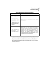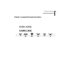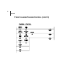
1
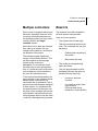
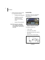
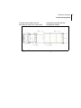
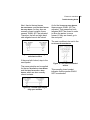
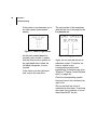
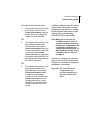
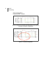
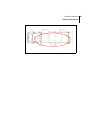
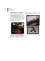
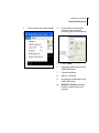
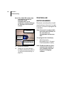
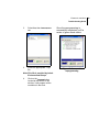
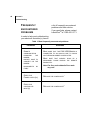
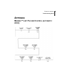
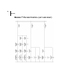
ELECTRONIC
CONTROLLERS
TROUBLESHOOTING
GUIDE
9/2/03
Part # : 90330
Electronic controllers
Troubleshooting Guide
Table of Content
Chapter
Introduction
Contacting Labrie Environmental Group ....................2
How it works ..................................................................2
Single controller .........................................................2
Multiple controllers .....................................................3
Benefits ..........................................................................3
Location .........................................................................4
Chapter 1
Safety
Safety Conventions .......................................................7
General Safety Notions .................................................8
Responsibilities of the Employer ................................9
Responsibilities of the Employee .............................10
Chapter 2
Troubleshooting
Configuration sheets ..................................................11
Error code interpretation ............................................12
iii
iv
Table of Contents
Blinking LED ............................................................12
Code signification ....................................................12
Communication status ........................................................13
Internal error ....................................................................... 13
Floating output ................................................................... 13
Over current output ............................................................ 13
How to use logic diagrams ........................................14
Symbols ...................................................................14
Reading ...................................................................17
Troubleshooting by using a computer ......................22
Installing the debugging software ............................23
Connecting the material ...........................................23
Diagnostic connectors ........................................................26
Launching the software ...........................................27
Screen details ..........................................................28
Legend ............................................................................... 29
How to display all the signal names ................................... 31
In the field troubleshooting ......................................32
Example ............................................................................. 32
Pin out ................................................................................ 37
Remote troubleshooting ..................................................... 40
Controller reprogramming .........................................42
Electronic controllers
Troubleshooting Guide
Frequently encountered problems ............................44
Chapter
Appendix
Minimax™ Left Packer Control (automatic mode) ...47
Minimax™ Packer Control (left and right) ................48
Front Loader Packer Control .....................................49
Debugging Software Installation (for Windows XP/
2000) .............................................................................52
Final steps for Windows XP only .........................64
Final steps for Windows 2000 only ......................69
v
vi
Table of Contents
Electronic controllers
Troubleshooting Guide
INTRODUCTION
Thanks to all technological progresses
made throughout the past few years,
the world of electrical and electronic
systems has evolved in a fulgurant
way. In fact, the electrical and
electronic components are now more
reliable and efficient than ever. Also,
they generally allow to reduce the
operating costs, the complexity and the
weight of numerous systems.
As one of the leader in the refuse truck
manufacturing industry, Labrie
Environmental Group decided to take
advantage of the technology and all
the benefits it presents by
implementing electronic controllers in
some of its trucks.
Therefore, the purpose of this
publication is to explain clearly the
electronic controllers functions and
also to support the maintenance
personnel in their troubleshooting. It
contains all the essential informations
needed to perform the maintenance
and troubleshooting of the electronic
controller(s) installed in the truck.
We hope that you’ll appreciate this
manual.
If you have some problems with a
Labrie unit, please contact your
distributor first. He should be able to
help you and give you all technical
informations you need.
1
2
How it works
CONTACTING LABRIE
ENVIRONMENTAL GROUP
LabriePlusTM
3630 Stearns Drive
Oshkosh, WI 54904
Parts, Service and Warranty
(during business hours)
Technical Support Service
(24 hours)
Toll free: 1-800-231-2771
Telephone: 1-920-233-2770
General Fax: 1-920-232-2496
Sales Fax: 1-920-232-2498
Mailing address:
P.O. Box 2785
Oshkosh, WI 54903-2785
Web site: www.labriegroup.com
E-mail: [email protected]
HOW IT WORKS
Single controller
The electronic controller controls,
partially or completely depending on
the vehicle model, the logic of the truck
(packer sequence, interlocks, lights,
etc.). All the functions are now
integrated in one device, reducing the
number of wires, the complexity of the
system and replacing all the relays
formerly used to perform all the logical
functions, without changing anything in
the operation principles.
One of the numerous benefits of this
controller is that it allows to quickly add
new functions to the truck only by
reprogramming the system.
This controller also allows to make the
diagnostic, in the field or remotely, of
the system by using a computer (the
proper software must be installed).
That way, you can see the status of all
the inputs and outputs on your
computer screen.To simplify
troubleshooting even more, some
controllers display error codes, which
may indicate the cause of the problem.
Electronic controllers
Troubleshooting Guide
Multiple controllers
BENEFITS
When a truck is equipped with several
electronic controllers, these are used
to transmit informations between all
the electrical systems, on top of all the
functions listed in the Single
controller section.
The electronic controllers installed in
the truck present many benefits.
Here are a few examples :
•
They replace the old relay logic.
•
There’s less electrical wires on the
truck. The controllers use only few
harnesses.
When there’s more than one controller,
they make up a network. We can
compare this network to a conference
call between a few people.
The controllers speak together by
using a communication protocol. This
can be compared to the language
spoken by the conference
participants.To communicate, each
controller uses a receiver/transmitter
chip. In a conference call, each person
uses a telephone, which transforms
the voice into electrical pulses.
To be received and interpreted by the
good controller, each message should
indicate where it comes from, its
importance and its destination. That’s
why each controller has been assigned
a node number. In a conference call,
the speech timber indicates who is at
the origin of the message and the rank
of the speaker determines the priority
of his message, that is to say the order
in which the messages are processed.
•
Reducing the complexity of
the system
•
May reduce the costs
•
They make the troubleshooting
easier and faster.
•
They are programmable to allow
presetting functions that were not
possible with the relay logic.
•
It’s easy to add new
functions
•
It is simple to modify truck
logic at Labrie
Environmental Group,
distributor or client facilities
3
4
How it works
•
All the inputs and outputs are tied
to a computerized controller
•
Enabling remote diagnostic
•
Possibility to see all the
electrical inputs and
outputs via a computer
screen
•
Number of fuses reduced
Note:The electronic controllers
don’t change the interlocks
nor the theory of operation of
the truck.
LOCATION
Depending on the truck configuration,
the controllers can be located at
different places.
Figure 1. Electronic controller
The possible locations are:
•
In the console
•
At the back of the vehicle
•
On each side of the truck, near the
block valve
•
Under the truck, on the chassis
Figure 2. Controller possible
locations
Electronic controllers
Troubleshooting Guide
To know exactly where are the
controllers on your truck, refer to the
schematics provided with the
configuration sheets.
Figure 3. Example of schematic indicating the controllers location
5
6
How it works
Electronic controllers
Troubleshooting Guide
SAFETY
Since Labrie Environmental Group
sells heavy duty vehicles, their use
entitles a number of safety issues.
Such issues, along with all necessary
safety instructions and conventions,
are presented in this section of the
Manual.
SAFETY CONVENTIONS
DANGER
INDICATES
AN
IMMINENTLY
HAZARDOUS SITUATION WHICH, IF
NOT AVOIDED, WILL RESULT IN
DEATH OR SERIOUS INJURY.
WARNING
INDICATES
A
POTENTIALLY
HAZARDOUS SITUATION WHICH, IF
NOT AVOIDED, COULD RESULT IN
DEATH OR SERIOUS INJURY.
CAUTION
INDICATES
A
POTENTIALLY
HAZARDOUS SITUATION WHICH, IF
NOT AVOIDED, MAY RESULT IN
MINOR OR MODERATE INJURY.
7
8
CHAPTER 2
Safety
GENERAL SAFETY NOTIONS
It is important to state that despite
Labrie Environmental Group’s
commitment to provide its customers
with the most reliable vehicles, the
main safety feature remains in the
user's commitment to respect all safety
notations expressed in this guide and
labels on the vehicle as well as use the
product responsibly.
Note:The following are safety
notions that are related to the
use of Labrie Environmental
Group’s trucks.
IMPORTANT
READ
AND
THOROUGHLY
UNDERSTAND
THE
CURRENT
MANUAL BEFORE PERFORMING
ANY
ADJUSTMENT
ON
THE
VEHICLE.
THOROUGH
OF
THE
UNDERSTANDING
OPERATOR MANUAL IS ALSO
MANDATORY BEFORE OPERATING
THE VEHICLE.
DANGER
ALWAYS BE AWARE OF THE
VEHICLE’S SURROUNDINGS TO
MAKE SURE NO PEDESTRIANS,
PASSERSBY, BYSTANDERS, OR
OTHER PEOPLE OR VEHICLES
ARE IN ANY WAY EXPOSED TO
ANY DANGER CAUSED BY THE
USE OF THE TRUCK.
Electronic controllers
Troubleshooting Guide
Responsibilities of
the Employer
It is the employer’s responsibility:
•
•
•
•
•
To ensure the operation of the truck
is in accordance with all safety
requirements and codes, including
all applicable regulations, the
Occupational Safety and Health
Act (OSHA) and the American
National Standards Institute
(ANSI).
To ensure the employees are
qualified for the operation of the
equipment and take all safety
measures before working with this
equipment.
To properly maintain all mobile
equipment to meet all provincial/
state and federal safety standards.
To supply adequate instructions
and training for the safe use of the
vehicle before assigning the
employee to such equipment.
To keep the vehicle maintained and
properly adjusted to meet the
manufacturer’s standards and
recommendations. For help or
more information, contact the
manufacturer or any authorized
representative.
•
To keep record of any breakdowns
or malfunctions of the vehicle as
well as any inspection and
maintenance.
•
To ensure the repair of any failures
or malfunctions that may affect the
safe use of the vehicle is always
performed before it is used again.
•
To meet the appropriate lighting
requirements for night shift work (if
permitted).
•
To regularly accompany the
operator of the vehicle and take
measures to ensure the smooth
and safe operation of the vehicle.
•
To make sure that the backup
alarm works properly while the
vehicle is in reverse.
•
To take the necessary measures
that follow a damage or
malfunction report from any
employee.
•
To establish and ensure the
application of a “Lockout/Tagout
Procedure” at the time of any
inspection, repair or maintenance
to the vehicle, regardless of
whether it takes place on the road
or in the garage.
9
10
CHAPTER 2
Safety
Responsibilities of
the Employee
It is the employee’s responsibility:
•
To enforce all safety measures to
meet the requirements established
by the employer.
•
To operate the truck only after
having received instructions and
training.
•
To immediately report to the
employer or supervisor about any
damage or malfunction of the
vehicle.
•
To make sure that there is nobody
near the vehicle before activating
any of the controls and be
prepared to stop everything upon
the existence of possible danger.
•
To wear a grounding bracelet when
manipulating the modules. Static
electricity can damage the inputs
and outputs.
Electronic controllers
Troubleshooting Guide
TROUBLESHOOTING
IN CASE OF PROBLEM
CONFIGURATION SHEETS
If an electrical or electronic problem
occurs, please refer to the electrical
diagrams provided with the truck.
The configuration sheets provided
with the truck contain tools that will
help you troubleshooting the
electronic controllers.
If the electrical diagrams reveal that
there’s an electronic controller
involved in the faulty system, apply
the following procedure:
1.
Perform a visual inspection of
the truck. Sometimes, the cause
of a problem can be easily
detected.
2.
If the problem persists and
there’s a controller in the cab
console, open the console to
reach the controller and read its
display.
3.
Write down the error code. Refer
to “Error code interpretation” on
page 12.
4.
If there’s no error code or if the
controller is not equipped with a
display, refer to the logic
diagrams provided with the truck
to perform troubleshooting.
Refer to “How to use logic
diagrams” on page 14.
These configuration sheets contain:
•
Tables that describe the inputs and
outputs (refer to “Table describing
inputs and outputs” on page 38)
•
The pin out of all the connectors
(refer to “Controller connectors (pin
out)” on page 39).
•
The general logic diagrams (to see
an example, refer to “Minimax™
Packer Control (left and right)” on
page 48)
•
The controllers location on the
truck (refer to “Example of
schematic indicating the controllers
location” on page 5)
11
12
CHAPTER 2
Troubleshooting
ERROR CODE
Code signification
INTERPRETATION
Four types of messages can be
displayed:
To know what an error code means,
it is necessary to know how to
interpret it.
Blinking LED
When the LED is green and
blinking, that means everything is
running well and there’s a message
communicated.
If the LED is solid green, that
means that everything is running
well but that there’s no message
communicated.
If the LED is flashing red or red and
green, that means that there’s an
internal error and that it is
necessary to reprogram the
controller.
•
Communication status
•
Internal error
•
Floating output
•
Over current output
Electronic controllers
Troubleshooting Guide
Communication status
Internal error
• The code begins by the letter n.
• The second position LED indicates the controller number.
• The last two digits indicate the
status of communication
• The code begins by 0 or 3.
• Call LabriePlusTM.
•
on means it is active
•
of means that it is inactive
Floating output
A floating output can be caused by
a cut wire or an unplugged device.
• The code begins by 1.
• The second digit indicates the
controller number.
• The last two digits represent the
output number
Over current output
Figure 4. Controller 1 is active
An overcurrent output can be
caused by a short-circuit or a
defective device.
• The code begins by 2.
• The second digit indicates the
controller number.
• The last two digits represent the
output number.
Figure 5. Controller 2 is inactive
Figure 6. The curent at the output
#10 of the controller 1 exceeded the
rated value.
13
14
CHAPTER 2
Troubleshooting
Note:The input and output numbers
and their corresponding
function are listed in the
configuration sheets provided
with the truck (refer to
“Configuration sheets” on
page 11). To know which
function corresponds to the
output number displayed,
refer to these configuration
sheets.
Figure 7. Example of configuration
sheet
HOW TO USE LOGIC
DIAGRAMS
Symbols
With each truck are provided not
only configuration sheets but also
logic diagrams. The logic diagrams
are simplified schematics that will
help you troubleshooting the
systems controlled by the
controller(s). If your truck is
equipped with a particular option
that doesn’t figure on the logic
diagrams, please refer to the
electrical schematic provided with
the truck.
Electronic controllers
Troubleshooting Guide
First, let’s see what the different
symbols of these logic diagrams
mean.
The following represents the
normally open contact (N.O.) of a
switch, meaning that the function
has to be activated in order to have
a signal at the output:
Figure 8. Normally open contact
The next one represents the
normally closed contact of a switch,
meaning that the function shall not
be activated in order to have a
signal at the output:
Figure 9. Normally closed contact
The following symbol can
interpreted two different ways:
If there’s an output number under it
(e.g. 02.3), that means that this is
the end of the circuit.
If there’s no number under it, that
means that the diagram continues
on another page (see Figure 10.
“Symbol indicating that the circuit
continues on another page”). To
know exactly where it continues,
you only have to find the
corresponding symbol on the other
page (see Figure 11. “Symbol
15
16
CHAPTER 2
Troubleshooting
indicating where the circuit
continues”).
Figure 10. Symbol indicating that
the circuit continues on another
page
Figure 11. Symbol indicating where
the circuit continues
Electronic controllers
Troubleshooting Guide
Reading
Here is an example that will help
you understanding how to read the
logic diagrams.
Note:This example refers to a
Minimax™ Co-Mingle
equipped with three control
stations (in the cab, on the
left-hand side and on the
right-hand side of the
truck).The goal of this
exercise is to explain the
principles of a logic diagram.
Let’s assume that, in the Automatic
Mode, the left-hand side packer is
not moving forward when you push
on the GREEN BUTTON .
Note:If your controller is not
equipped with a display or if
there’s no code displayed,
you’ll have to refer to the
electrical diagrams to
troubleshoot the system.
As we have to see at first glance if
all the the conditions are met, let’s
start the analyse at the end of the
Left Packer Control diagram
(reading from right to left).
Refer to “Minimax™ Left Packer
Control (automatic mode)” on
page 47 and take a look at the last
symbol of the circuit (LEFT PACKER
FORWARD SIGNAL).You can see that it’s
written O2.2 under it.
The first letter indicates if it is an
input (I) or an output (O). The
following digit indicates the node
number and the last one, the pin
number. So, O2.2 means that it is
an output located at pin #2 of the
node #2.
Note:In Bootloader, the node #2 will
be identified as node #1
(always substract 1 from the
node number displayed in the
DMS software.
Figure 12. Output at the end of a
circuit
17
18
CHAPTER 2
Troubleshooting
Note:This identification will
facilitate the troubleshooting.
To know the details of an
output or an input, refer to the
configuration sheets provided
with the truck (see Figure 7.
“Example of configuration
sheet”).
won’t take a look at the circuit
it refers to. To see the detailed
circuit corresponding to this
point, refer to the page where
the corresponding symbol is
(see Figure 13.
“Corresponding symbol”).
If you step back to the left, you can
see a point called FLAG RESET LEFT
PACKER.
As this represents a normally
closed contact (see Figure 9.
“Normally closed contact”), this
condition SHALL NOT be activated,
meaning in that case that the
packer MUST NOT be reset.
You can see that there’s no
indication below that symbol,
meaning it refers to another part of
the circuit. The other part it refers to
explains which conditions has to be
met to reset the packer.
Note:As we assume that this
condition is not activated, we
Figure 13. Corresponding symbol
Electronic controllers
Troubleshooting Guide
Next, there’s the LEFT TAILGATE
UNLOCKED SENSOR and the RIGHT TAILGATE
UNLOCKED SENSOR. As they also are
normally closed contacts, these
sensors SHALL NOT be activated.
Therefore, the left and right-hand
side tailgates have to be locked.
As for the TAILGATE UNLOCKED SENSORS,
these sensors SHALL NOT be
activated. That means that both
tailgates MUST be closed in order
to allow the packer to move
forward. If they are closed, go to
the next point.
The next condition to be met is the
LEFT PACKER EXTENDED SENSOR.
Figure 14. Left and right tailgate
unlocked sensors
If they are both locked, step to the
next symbol.
The same principle can be applied
for the LEFT TAILGATE FULLY OPEN SENSOR
and the RIGHT TAILGATE FULLY OPEN
SENSOR, which are also normally
closed contacts.
Figure 15. Left and right tailgate
fully open sensors
Figure 16. Left packer extended
sensor
This normally closed contact
indicates that the packer SHALL
NOT be extended.
19
20
CHAPTER 2
Troubleshooting
If the packer is not extended, go to
the next symbol (CHUTE TO RIGHT
SENSOR).
The next symbol of this sequence
(and the last one of this page) is the
FLAG GREEN BUTTON.
Figure 17. Chute to right sensor
As the CHUTE TO RIGHT SENSOR is a
normally open contact, it means
that the chute must be placed on
the right-hand side to allow the
left-hand side packer to move
forward.
If the chute is on the right-hand
side, step to the next point.
Figure 18. Flag green button
Again, we can see that there’s no
indication under it. Therefore, we
have to search for the
corresponding symbol (with
parenthesis) on another page (see
“Minimax™ Packer Control (left and
right)” on page 48).
Once the corresponding symbol
has been found, let’s continue from
right to left.
We can see that the circuit is
subdvided in three lines. To activate
the output, the conditions of one of
these lines MUST be met.
Electronic controllers
Troubleshooting Guide
Let’s take a look at these lines:
1.
The operator has to push on the
green button on the console
(PACKER FORWARD SWITCH, CAB) and
neither the left nor right packer
control has to be activated.
OR
2.
The operator has to push on the
green button located on the
left-hand side control station
(PACKER FORWARD SWITCH, LEFT), the
left-hand side packer control has
to be selected (LEFT PACKER
CONTROL SELECTOR), the right-hand
side packer control shall NOT be
selected and the right-hand side
door MUST be closed.
OR
3.
The operator has to push on the
green button located on the
right-hand side control station
(PACKER FORWARD SWITCH, RIGHT),
the right-hand side packer
control has to be selected (LEFT
PACKER CONTROL SELECTOR), the
left-hand side packer control
shall NOT be selected and the
left-hand side door MUST be
closed.
If all the conditions are met to allow
the left-hand side packer working
properly but that there’s no voltage
at the left-hand side packer output,
replacing the corresponding
controller CAN be a possibility.
Note:When you’re not sure if a
condition is met or not or if
you want to check the wiring
between two components, use
a voltmeter to measure the
voltage at particular points. To
take measures directly on the
controller, refer to “Pin out”
on page 37.
If there’s no voltage at a particular
point of the circuit, the mechanics
will have to troubleshoot deeply the
problematic component.
Important: The controllers don’t
change neither the
operation principles nor
the safety sytems of the
truck.
21
22
CHAPTER 2
Troubleshooting
Note:In this example, the chute is a
good way to troubleshoot the
system. In fact, it is the chute
position that determines
which packer will be used. If
you place the chute on the left
and that the right-hand side
packer is working properly,
you won’t have to
troubleshoot the elements
both systems have in
common.
Note:Each element of the logic
diagrams are identified with a
letter and numbers that
indicate their nature (output or
input), their controller and to
which pin number they
correspond.
Important: The pin out of the
controller connectors are
provided with the truck
(configuration sheets).
TROUBLESHOOTING BY
USING A COMPUTER
It is possible to troubleshoot the
electronic controllers in the field or
remotely by using a computer.
However, it is necessary to get the
proper material to do it.
Neccesary material:
•
Computer with Windows XP/2000
Operating System
•
Debugging Software CD
•
CAN USB modem
•
USB cable
•
Diagnostic cable kit
Important: It is mandatory to do a
training course before
troubleshooting the system
by using a computer and
all the material listed
above. Call Labrie
Environmental Group to
enroll for training classes.
Electronic controllers
Troubleshooting Guide
Note:Communicate with Labrie
Environmental Group for more
details on the material needed.
Installing the
debugging software
To install the software:
Figure 19. CAN USB Modem with
cables
•
Put the CD in the computer
•
Follow the installation instructions
on screen. See “Debugging
Software Installation (for Windows
XP/2000)” on page 52.
Connecting the
material
To connect the material for in the
field troubleshooting, perform the
following steps:
1.
Connect the computer to the
CAN USB modem and the CAN
USB modem into the NODE 1
controller.
Note:If there’s an electronic
controller in the console, this
is where you have to plug the
CAN USB modem (in the
appropriate port). If there’s no
controller in the cab console,
refer to the configuration
23
24
CHAPTER 2
Troubleshooting
sheets to know where is
located the NODE 1 controller.
Figure 20. Example of a schematic indicating where are the different
controllers (4 modules configuration)
Figure 21. 2 modules configuration
Electronic controllers
Troubleshooting Guide
Figure 22. 3 modules configuration
25
26
CHAPTER 2
Troubleshooting
Diagnostic connectors
with 3 or 4 pins (depending on the
truck model).
Depending on the truck model, you
can find several diagnostic
connector types. On some vehicles,
the diagnostic connector is located
on the console. In that case, it is a
AMP type connector.
a
As for the modules located on each
side of the vehicle, their diagnostic
connectors can be Deutsch type
Electronic controllers
Troubleshooting Guide
Launching the
software
1.
Launch the debugging software:
Start - Program - Delastek Delastek multiplex system
2.
Don’t enter any password (it is
only for programming).
3.
Load the appropriate file by
clicking on the OPEN icon (upper
left side of the window, beside
the SAVE icon). Make sure that
the NODES tab is open.
Note:Each truck has its particular
file. You’ll find the five-digit
file number in the console or
on the module(s).
4.
Click on the VIEW button to see all
the input/output signals.
Figure 23. VIEW button
27
28
CHAPTER 2
Troubleshooting
Screen details
Once the appropriate file is
downloaded, here is an example of
what will appear on your computer
screen:
Figure 24. Typical screen of the debugging software
The rectangle represents the
controller. The node number is
located in the upper left corner of
the rectangle.
On each side of the rectangle are
two series of numbers, which
represent the inputs (left), the
outputs (right) and their
corresponding pin number.
Electronic controllers
Troubleshooting Guide
Legend
•
Yellow diamond
To help you troubleshooting the
controller, you will find various
symbols that indicate the state of
each input/output.
Let’s take a look at these symbols:
•
Green diamond
The yellow diamond shows a
hardware output that is
undercurrent (open load).
•
Black square with white outline
The green diamond indicates an
enabled hardware output.
•
Red diamond
The black and white square
indicates an activated logic output.
The red diamond indicates a
hardware output that is
short-citrcuited (over current).
29
30
CHAPTER 2
Troubleshooting
•
White square
To each output or input number
corresponds a green line. If this line
is long, that means that the output/
input is programmed. If the green
line is short, that means that the
output/input is unprogrammed.
The white square indicates an
activated hardware input
Figure 25. Input/output green lines
When there’s no symbol at all
beside a programmed pin number,
that means that the input/output is
disabled.
When a number appears beside an
input/output, that means that the
input/output is analog or PWM
(pulse width modulation).
If the signal is blinking, it
corresponds to a flashing light on
the truck.
Electronic controllers
Troubleshooting Guide
How to display all the
signal names
If you want to know the name of all
the inputs and outputs, just press
on the space bar.
Figure 26. Signal names
All the signal names will appear in
yellow.
31
32
CHAPTER 2
Troubleshooting
In the field
troubleshooting
The debugging software is like a
big multimeter used to know the
state of each input/output. This tool
has been created to help you
troubleshooting the truck more
quickly and easily.
Note:This tool doesn’t find
automatically the cause of a
problem. It was created to help
you troubleshooting the truck
systems by presenting the
state of all the inputs and
outputs.
Example
To clearly understand this example,
refer to the screen shots below and
to “Front Loader Packer Control” on
page 49 (Appendix).
Scenario
The packer of your LabrieTM Front
Loader doesn’t move forward when
you push on the green button.
You perform a visual inspection
first, but it doesn’t help you to find
what causes the problem.
You plug your computer on the
controller (see “Connecting the
material” on page 23) and you
launch the debugging software (see
“Launching the software” on
page 27).
By taking a look to the packer
control logic diagram (automatic
mode), you see that the PACKER
FORWARD SIGNAL output number is
O1.1.
You check on your computer
screen and notice that the output
#1 is not activated (see Figure 27.
“Output #1 not activated”).
Electronic controllers
Troubleshooting Guide
As some conditions must be met to
allow the packer moving forward,
you take a look at the logic diagram
to see which functions must be
activated or not.
•
The tailgate has to be closed (input
#11)
•
The tailgate has to be locked (input
#10)
•
The packer shall not be extended
(input #15)
The diagram reveals that:
•
The hopper door has to be closed
(input #13)
•
The packer green button must be
pushed on (input #6)
•
The roof must be open (input #12)
•
•
The Emergency stop button shall
not be pushed on (input #5)
The pump must be activated
(output #16) by turning on the PTO
switch (input #9)
•
The packer shall not be reset in
any way
Figure 27. Output #1 not activated
33
34
CHAPTER 2
Troubleshooting
Let’s take a closer look at the
outputs and inputs shown on the
screen:
Figure 28. No signal at the PACKER FORWARD output
Electronic controllers
Troubleshooting Guide
You have to check if all the
conditions mentionned above are
met. Let’s assume that the packer
is not reset in any way.
•
The roof is open (input #12)
•
The packer is not extended (input
#15)
Note:This condition shall not be
met, that’s why it is not
activated on the computer
screen.
•
The packer green button is
activated (input #6)
•
The tailgate is closed (input #11)
Note:As the TAILGATE UNLOCKED
condition (I1.11) shall not be
met (see Figure 9. “Normally
closed contact”, “Front
Loader Packer Control” on
page 49 and “Front Loader
Pump” on page 51), that’s why
this input is not activated on
the computer screen.
•
The tailgate is locked (input #10)
Note:This condition shall not be
met, that’s why it is not
activated on the computer
screen.
•
The hopper door is closed (input
#13)
•
The Emergency stop button is not
activated (input #5)
•
The pump is not activated (output
#16) and the PTO switch (input #9)
is not turned ON.
As we can see, the pump is not
turned ON. That can be the cause of
the problem. Let’s see the result
when the pump is turned ON.
35
36
CHAPTER 2
Troubleshooting
Figure 29. Packer working properly
As you can see, the PTO switch is
turned ON (input #9), the pump is
activated (output #16) and there’s a
signal at the output #1.
If the packer stills not moving
forward after that, the problem is
located between the controller and
the packer.
Note:There’s a possibility for the
output to be defective even if
the software indicates that
there’s a signal at this output.
To make sure that the output
is correct, measure its
voltage.
Electronic controllers
Troubleshooting Guide
If there’s no voltage at this output,
replace the controller. If there’s 12V
at this output, check all the wires
and components between the
packer and the output of the
controller to find the cause of the
problem.
Pin out
To know which connector and pin
numbers correspond to each one of
the inputs/outputs, refer to the
configuration sheets provided with
the truck. You’ll find tables that
describe in details all the inputs and
outputs.
37
38
CHAPTER 2
Troubleshooting
Figure 30. Table describing inputs and outputs
The first column (I/O) contains all
the input and output numbers. The
inputs begin by “I” and outputs by
“O”.
The second column indicates if the
input/output is analog (A) or digital
(D).
The third column (Pos/Neg)
indicates if the input/output is
positive or negative (contact to
ground).
Electronic controllers
Troubleshooting Guide
Positive means that the input/
output is activated by applying 12V.
Negative means that the input/
output is activated by applying 0V
(ground).
The fourth column indicates the
maximum current rating of the
module and the current rating set
by Labrie Environmental Group.
If the set current of a particular
function is 2A and that its maximum
current rating is 5A, the fuse will trip
off if the device draws more than
2A.
The fifth column presents the
connector number.
The sixth column contains the
connector pin number
corresponding to each input/output.
The next-to-last column gives the
wire number corresponding to each
input/output.
Finally, the last column contains a
description of the inputs/outputs.
To know where are located each
pin and connector, check the
position number indicated directly
on the connector or refer to the
configuration sheets, which contain
views representing the different
controller connectors.
Figure 31. Controller connectors (pin out)
39
40
CHAPTER 2
Troubleshooting
Remote troubleshooting
2.
Plug the other end of the CAN
USB modem on a direct phone
line.
3.
Call Labrie Environmental Group
and give the phone number to
the person who will troubleshoot
remotely.
To perform remote troubleshooting,
the process is almost the same as
the in the field troubleshooting
(refer to “In the field
troubleshooting” on page 32). The
procedure is divided in two parts:
one procedure for the person who
is troubleshooting remotely and one
procedure for the maintenance
personnel in the field.
Procedure for the maintenance
personnel:
1.
Plug one end of the CAN USB
modem on the diagnostic
connector.
Procedure for the person who is
troubleshooting remotely:
Figure 32. Diagnostic connector
1.
Connect the CAN USB modem
to a phone line and to your
computer.
2.
Start the debugging software
(refer to “Launching the
software” on page 27).
Electronic controllers
Troubleshooting Guide
3.
Click on TOOLS and select OPTIONS.
4.
At the bottom of the window,
enter the customer phone
number (given by the customer).
5.
Click on SEND.
6.
Unplug the USB cable from the
CAN USB Modem.
7.
Close the software.
8.
Wait for 2 seconds.
9.
Plug back the USB cable to the
CAN USB Modem.
10.
WITHOUT DELAY, press and
hold the modem button for 3
seconds.
41
42
CHAPTER 2
Troubleshooting
Note:If the CAN USB modem light
stop flashing, repeat the
procedure. If the
communication is not
established, another LED may
be flashing in the CAN USB
modem.
Push on the CAN USB
button before this LED
stops flashing
When On, the phone
communication is
established with another modem
CONTROLLER
REPROGRAMMING
Electronic controllers allow to add
new functions to the truck. In order
to do so, you have to reprogram the
controllers.
Note:If the truck is equipped with
more than one controller, all
the controllers are
reprogrammed at the same
time.
To reprogram the controller(s):
When this LED is ON, the communication is established with the
module or the laptop. When OFF,
the communication is interrupted
11.
Launch the software.
12.
Debug as if you were doing in
the field troubleshooting (refer to
“In the field troubleshooting” on
page 32).
1.
Start the program
BootLoader.exe (C:\Program
Files\Delastek\Boot Loader).
Note:The BootLoader.exe file is
automatically installed on
your computer when you
install the debugging
software.
Electronic controllers
Troubleshooting Guide
2.
Select FILE, then OPEN EQUATION
FILE.
3.
Select the appropriate “.cmp”
file.
Note:This file is provided by Labrie
Environmental Group.
4.
Click on the PROGRAM button
located at the bottom of the
window. It will program all the
controllers in the truck.
Once the reprogramming is
successfully completed, you’ll a
series of green check marks.
Figure 33. Successful
reprogramming
43
44
CHAPTER 2
Troubleshooting
FREQUENTLY
a list of frequently encountered
problems and their solution.
ENCOUNTERED
If you need help, please contact
LabriePlusTM at 1-800-231-2771.
PROBLEMS
In order to help you troubleshooting
your electronic controller(s), here is
Table 1: Most frequently encountered problems
Problems
Solutions
REMOTE
COMMUNICATION
PROBLEMS.
THE
MODEM
DOESN’T WANT TO
CONNECT OR THE
MODEM
DISCONNECTS BY
ITSELF
MAKE SURE THAT THE CAN USB MODEM IS
CONNECTED TO AN ANALOG LINE TO WHICH
NO EXTENSION NUMBER IS DEDICATED.
MAKE SURE THAT NOBODY PICKS UP A
SECONDARY PHONE DURING THE REMOTE
DIAGNOSTIC.
DEFECTIVE
POWER OUTPUT(S)
REPLACE THE CONTROLLER.1
Note:Fax lines and residential lines work
very well
DEFECTIVE
CONTROLLER
INPUT(S)
REPLACE THE CONTROLLER.2
Electronic controllers
Troubleshooting Guide
Table 1: Most frequently encountered problems
Problems
Solutions
THE
CONTROLLER
IS
DEPROGRAMMING
BY ITSELF (THE
CONTROLLER LED
TURNS RED OR IS
BLINKING RED AND
GREEN)
REPROGRAM
THE CONTROLLER IN THE FIELD
OR REMOTELY.
MAKE
THE
SOFTWARE IS
AN
DETECTING
OPEN LIMIT SWITCH
SURE THAT THE GREASE APPLIED ONT
THE LIMIT SWITCH CONTACTS IS DIALECTRIC
GREASE ONLY. BECAUSE THE MODULE IS
SENSITIVE TO HIGH IMPEDANCE, AN EXCESS
AMOUNT OF NORMAL GREASE ON THE
CONNECTORS MIGHT BE INTERPRETED AS A
CLOSED CIRCUIT BY THE MODULE.
1. To know if an output is defective, you have to verify it by using a the debugging software
in diagnostic mode. Before, all the conditions MUST be met in order to activate the output. If a positive output (see the configuration sheets to know if an output is positive or
negative) is activated on the screen but that you measure 0 volt (ground) on its corresponding pin, the output is probably defective. If a negative output seems activated on
the screen but that you measure the supply voltage (about 12 volts) on its pin, the output
is probably defective too.
45
46
CHAPTER 2
Troubleshooting
2. To know if an input is defective, you have to verify it by using a the debugging software
in diagnostic mode. Before, all the conditions MUST be met in order to activate the
input. If a positive input (see the configuration sheets to know if an input is positive or
negative) is not activated on the screen but that you measure 12 volts on its pin, the input
is probably defective. If a negative input is not activated on the screen but that you measure 0 volt (ground) on its pin, the input is probably defective too.
Electronic controllers
Troubleshooting Guide
APPENDIX
MINIMAX™ LEFT PACKER CONTROL (AUTOMATIC
MODE)
47
48
Appendix
MINIMAX™ PACKER CONTROL (LEFT AND RIGHT)
Electronic controllers
Troubleshooting Guide
FRONT LOADER PACKER CONTROL
49
50
Appendix
FRONT LOADER PACKER CONTROL (CONT’D)
Electronic controllers
Troubleshooting Guide
FRONT LOADER PUMP
51
52
Appendix
DEBUGGING SOFTWARE INSTALLATION (FOR
WINDOWS XP/2000)
This guide will help you to easily install the debugging software. It is
important to follow each step in the order indicated below.
Before beginning:
•
Please close all running applications.
•
An “administrator” environment is necessary to proceed to this installation. If
it’s not the case, the application will ask you the “administrator password”.
•
Anti-virus programs must be deactivated before beginning the installation.
Some anti-virus programs prevent the installation of some drivers. Reactivate
the anti-virus once the installation is done.
•
For help, contact your network administrator.
•
The program execution will be ended if you don’t have one of these operating
systems:
•
Windows 98 SE
•
Windows 2000
•
Windows XP
Electronic controllers
Troubleshooting Guide
The software installation will start automatically after the insertion of the CD in
your CD_ROM drive. Follow the instructions on the screen.
1.
Click on OK to accept the installation of the Kvaser software (required for the
CAN USB Modem).
53
54
Appendix
2.
Click on NO at the following question.
Electronic controllers
Troubleshooting Guide
3.
Click on NEXT to start the installation.
55
56
Appendix
4.
Click on NEXT.
Electronic controllers
Troubleshooting Guide
5.
Keep the default installation directory (recommended) or choose a different
location and then click on NEXT.
Note:When using a different CAN USB modem, you don’t have to repeat
these steps. The software will detect the modem automatically.
57
58
Appendix
6.
Select NO, DON’T TRY TO REMOVE OLD DRIVERS, and click on NEXT.
Electronic controllers
Troubleshooting Guide
7.
Click on NEXT to begin the installation.
59
60
Appendix
8.
The installation of “Kvaser Can” drivers is finished. Click on OK.
Electronic controllers
Troubleshooting Guide
9.
Click on NEXT to launch the software installation.
61
62
Appendix
10.
Click on INSTALL to begin the installation.
Electronic controllers
Troubleshooting Guide
11.
You can now connect the CAN USB Modem (DMS COM) to the USB port.
Click on FINISH when done.
Note:The FOUND NEW HARDWARE WIZARD window may appear over this one before
you have time to click on FINISH. However, it is important to exit the
installation wizard before continuing. If this happens, make sure to
click on FINISH (see window below) without cancelling the new window.
63
64
Appendix
Final steps for Windows XP only
1.
Windows XP will detect the new hardware and the FOUND NEW HARDWARE
window will appear on the screen. Select NO, NOT THIS TIME and click on
NEXT to continue.
WIZARD
Note:If your computer is equipped with Windows 2000, refer to “Final steps
for Windows 2000 only” on page 69.
Electronic controllers
Troubleshooting Guide
2.
Select INSTALL FROM A LIST OR SPECIFIC LOCATION (ADVANCED), and click on NEXT to
continue.
65
66
Appendix
3.
Select SEARCH FOR THE BEST DRIVER IN THESE LOCATIONS AND ONLY CHECK SEARCH
Click on NEXT. If Windows didn’t found the
driver, you can try Program Files\Delastek\Delastek Multiplex
System\Drivers FTDI\FTD2xx.sys path on your CD-ROM or your installation
driver.
REMOVABLE MEDIA (FLOPPY, CD-ROM...).
Electronic controllers
Troubleshooting Guide
4.
When the following warning appears, click on CONTINUE ANYWAY.
67
68
Appendix
5.
Click on FINISH to complete the installation of the new hardware.
You are now ready to use the debugging software with the CAN USB Modem!
To launch the system, click on the DMS.EXE icon that you have now on your
desktop.
Electronic controllers
Troubleshooting Guide
Final steps for Windows 2000 only
1.
Windows 2000 will detect the new hardware and the FOUND NEW HARDWARE
WIZARD window will appear on the screen. Click on NEXT to continue.
69
70
Appendix
2.
Click on SEARCH FOR A SUITABLE DRIVER FOR MY DEVICE (RECOMMENDED) and then on
NEXT.
Electronic controllers
Troubleshooting Guide
3.
Select CD-ROM DRIVES and click on NEXT.
71
72
Appendix
4.
To install the driver found by Windows for this device, click on NEXT.
Electronic controllers
Troubleshooting Guide
5.
Click on FINISH to complete the installation of the new hardware.
You are now ready to use the debugging software with the CAN USB Modem!
To launch the system, click on the DMS.EXE icon that you have now on your
desktop.
73
74
Appendix