1
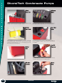
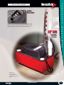
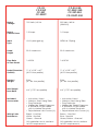
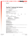
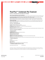
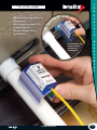
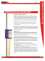
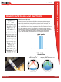
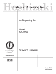
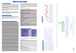
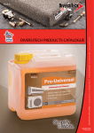
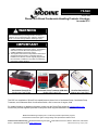
75-560
August, 2009
DiversiTech Brand Condensate Handling Products Literature
for model PTC
WARNING
Gas supply shall be shut-off and the electrical power
disconnected before proceeding with the conversion.
Failure to do so could result in fire, explosion, electrical
shock, or the unit starting suddenly resulting in injury.
IMPORTANT
1. The use of this manual is specifically intended for a
qualified installation and service agency. All installation
and service of these kits must be performed by a
qualified installation and service agency.
2. The supplier instructions that ship with the DiversiTech
accessories must be used in conjunction with the
Installation and Service manual originally shipped with
the unit heater, in addition to any other accompanying
component supplier literature.
Condensate Pump CP-22
Modine Item Code 57869
Condensate Pump Treatment SCM-186-6
Modine Item Code 57871
Overflow Switch SOS-1
Modine Item Code 57927
This PDF is a compilation of DiversiTech created literature pieces for the Condensate Pump, Condensate Pump
Treatment, and Condensate Drain Line Overflow Switch, and is current as of August, 2009.
For updated literature or additional information, please visit the DiversiTech website at www.diversitech.com.
DiversiTech products supplied by Modine will ship with vendor supplied installation instructions.
Modine Manufacturing Company has a continuous product improvement program,
and therefore reserves the right to change design and specifications without notice.
Commercial Products Group • Modine Manufacturing Company • 1500 DeKoven Avenue • Racine, Wisconsin, USA 53403
Phone: 1.800.828.4328 (HEAT) • www.modine.com
© Modine Manufacturing Company 2009
DiversiTech Condensate Pumps
C
O
N
D
E
N
S
A
T
E
Shatterproof stainless steel hang tabs have hole-and-slot design for easy
mounting. Tabs are located on convenient 8” centers.
Red, yellow, and green indicator lights show the pump status. Green for
power applied, yellow for pump running, and red for high level alarm.
A float manufactured from foamed polyethylene is a simple, chemical and
environmentally resistant, long lasting float. Rather than mold a trapped
air float from a material that sinks, or use an expanded polystyrene (EPS)
float, the DiversiTech float simply floats.
Four inlets versus two or three on other pumps provide the
greatest installation versatility. Inlet holes have a reinforced wall
for durability.
M
A
N
A
G
E
M
E
N
T
Rubber feet dampen vibration which reduces noise.
An elastomeric motor mounting gasket dampens vibration.
38
A pan tablet dispenser is included free with every pump. Perfectly
compatible with DiversiTech’s Pro-Treat® pan tablets.
Removable check valve for easy cleaning.
800.995.2222
C
This information is available as a contractor handout.
Order item number LIT-FLY-PUMP.
O
N
D
E
N
S
A
T
1/4” quick connect terminals provide easy connection to the built-in overflow
switch. Three terminals are provided allowing the installer flexibility to connect
air handler shut-down and optional alarm as needed. Switch features SPDT
isolated contacts ready for connection to building automation systems.
E
M
A
N
A
G
E
M
E
N
T
Suitable for use
with condensate from
condensing boilers and
high efficiency (condensing)
furnaces.
www.diversitech.com
39
Condensate
Pump
Installation and
Safety Instructions
CP-22
CP-22LP
CP-22T
CP-22LPT
CP-22-230
CP-22LP-230
CP-22T-230
CP-22LPT-230
Rated
Voltage
120 Volts / 60 Hz
220 Volts / 60 Hz
(208-230)
Rated
Current Draw
1.9 Amps
1.0 Amps
Input
Type
USA 3-prong plug
NEMA 6-15 plug
Head
Height
22 ft. maximum
22 ft. maximum
Flow Rate
at Zero Head
1.6 GPM
1.6 GPM
Product Dimensions
(LxWxH)
11.8” x 5.9“ x 6.7”
(4.9“H low profile)
11.8” x 5.9“ x 6.7”
(4.9“H low profile)
Product
Weight
5 lbs.
(4.7 lbs. low profile)
5 lbs.
(4.7 lbs. low profile)
Inlet Height
from Base
4.4” (1.75” low profile)
4.4” (1.75” low profile)
Included
Accessories
• Instruction Sheet
• Stainless Steel Hang Tabs
• Plug Protector
• Algaecide Tablet Dispenser
• 4’ Remote Shutoff Leads
with Insulated Terminals
• Polyethelene Inlet Covers (3)
• Instruction Sheet
• Stainless Steel Hang Tabs
• Plug Protector
• Algaecide Tablet Dispenser
• 4’ Remote Shutoff Leads
with Insulated Terminals
• Polyethelene Inlet Covers (3)
Wiring Color
References
Black - Live/Hot
White - Neutral
Green - Ground
Brown - Live/Hot
Blue - Neutral
Green/Yellow - Ground
All installations must conform
to NEC requirements
All installations must conform
to NEC requirements
General Information
Thank you for the purchase of this DiversiTech condensate pump. This
pump is designed to automatically remove the condensate water that
collects from appliances such as air conditioners, high-efficiency furnaces
and de-humidifiers.
The pump has a built-in tank that collects the water from the appliance.
When the water collected reaches sufficient level inside the pump tank,
the pump switches on and pumps the water to a remote location for
disposal. When the tank is sufficiently empty the pump automatically
switches off.
The pump is capable of lifting water to its rated height and is equipped
with a check valve that prevents water from flowing back into the tank
when the pump shuts off.
The pump is outfitted with lights that show the status of power available,
motor running and high water (alarm) conditions.
The pump is also equipped with a switch that activates when the water in
the tank reaches an overflow condition. The overflow safety switch may
be connected to turn off the appliance if the high water condition occurs.
The switch also has an alarm terminal that may optionally be connected to
an audible alarm or remote indicator light to indicate a trouble condition.
Pump should be stored indoors.
The chosen location should be clean and dry.
Unpacking
CHECK FOR
SHIPMENT
DAMAGE
Carefully open the carton to avoid damage to the pump. Do not use a
knife or other sharp object that may scratch the pumps cover. After
opening carton, look for damage. If damage is found file a claim with the
freight carrier.
CAUTION: Be sure to remove the cardboard insert. It is used to protect the
float during shipment. Failure to remove the insert will cause the pump to
run continuously.
Power Source
Supply voltage and frequency must match what is shown on the pump
nameplate. Source voltages lower than rated supply can reduce performance and cause the pump to overheat.
Pump Installation
The pump must be level and should be placed on a solid surface or floor.
The pump has rubber feet to reduce noise and keep it in place during
operation.
Do not use this pump in the presence of spraying or standing water, it may
cause a shock. This pump is not suitable for use in Class I or Class II
(explosive gas or dust locations).
Do not cover the pump air vents. The pump is air cooled. Do not cover
the vent holes located on the top or sides of the pump housing. The pump
may be operated continuously as long as the air vents are not covered.
Mounting
The condensate pump is equipped with metal mounting tabs which allow the
tank to be screwed to a wall or equipment side panel. The screw-to-screw
distance is 8”. When mounting into drywall or concrete walls the screws must
have anchors which provide the necessary support in the wall material.
The pump top is reversible. It may be turned around to allow easy access to
the pump outlet, pan tab tray or power connection as may be required by
the particular installation.
Inlets
4 inlet holes are located in the top deck of the pump. Flexible vinyl tubing
or PVC may be connected to any of the pump inlets. Pop out covers are
provided to cover unused inlets. Be sure to cover the unused holes to
prevent the pump from collecting debris or insects.
Tubing installed into the inlet holes must be straight. The tubing must not
bend inward where it will interfere with the pump or float mechanism.
When using rigid tubing such as PVC, be sure to cut the end at an angle.
This will allow the condensate water to drain freely and keep the tubing
end from being blocked by the tank bottom.
It may be desirable to use a “P” or “U” trap between the AC unit and the
condensate pump to provide a liquid barrier to air flow from the air conditioner. These types of “traps” always contain some water which blocks the
flow of air from the AC unit which is wasteful and can cause other problems such as accelerated algae growth.
Outlets and Tubing Conections
The pump is equipped with a combination barb-type fitting and check
valve. The fitting allows the connection of 3/8” flexible vinyl tubing such as
DiversiTech “CVT” clear vinyl. Attach the tubing by pressing it over the
barb fitting and secure with a screw type hose clamp.
Route the tubing up and away from the pump; avoid compressing or
kinking the tubing. The tube route should be the shortest possible distance
from the pump to the building exterior or other drain location. For best
results the distance that the water must go UP should be shorter than the
distance that it goes DOWN. With the longer DOWN tubing, the length will
help siphon the condensate from the tank, speeding the pump out time.
Pro-Treat® Tabs
The pump features a dispenser which holds DiversiTech Pro-Treat pan
treatment tablets. The dispenser may be filled with multiple tablets to aid in
keeping the pump, tank and outlet tubing slime free.
Pump Electrical Connections
Connect the pump power to a properly grounded outlet capable of
providing power that exceeds the requirements listed on the pump nameplate. Avoid the use of extension cords wherever possible. The pump must
be operated by a continuous source of power and must not be connected
to switched outlets or other power supplies that may be inadvertently or
automatically turned off.
All aspects of the installation must
conform to requirements of the NEC,
and any applicable local codes.
Safety Switch
The pump safety switch should be used
on 24V Class II control circuits only. The
pump safety switch connections are
available on standard ¼” quick connect
terminals located on the top cover.
Two wires with pre-crimped connectors may be plugged onto the
COMMON and RUN terminals and wired into the 24 Volt thermostat circuit
to shut off A/C systems should an overflow condition occur. The Safety
Switch operates with or without power provided to the pump. Optional
alarm or remote trouble light connection
The third terminal of the safety switch closes when the water exceeds the
high level limit. This terminal be connected to a light or buzzer to indicate
system trouble.
Pump Operation
Apply power by plugging in the pump. Check for green LED indication the
power is available. Test float and safety switch by filling the tank or manually operating the float. (see disassembly below)
Test Safety Switch operation (if used) to be sure that the A/C system shuts
down and the red ALARM LED lights when the float is raised to the upper
part of its travel.
Leak Check: Operate the pump by filling tank to trigger operation. Pump
RUN will be indicated by the yellow RUN LED.
Homeowner Instruction: Instruct the homeowner about the pump's general
operation, how to add Pro-Treat tablets, and to look for the ALARM LED if
they think that there is system trouble.
Pump Maintainance and Disassembly
Always disconnect power before performing maintenance. Pump and
deck may be removed from the tank by pushing tabs located on the tank
sides away from the deck while lifting on the pump cover.
Periodically inspect the Pump tank to assure it is free of accumulated dirt or
sludge. Do not use solvent cleaners. Clean Tank with soap and warm
water only. The check valve may be removed for cleaning or replacement by unscrewing with a 9/16 wrench. (illustration)
Clean inlet and outlet piping. Tubing may be cleared
of slime or debris instantly with a Wagner brand
Gallo Gun tool and Swoosh cartridges.
Add Pro-Treat Tabs to the tablet tray.
Reassemble system and check
for correct operation.
Limited Warranty
All pumps manufactured by or for DiversiTech Corporation (the Company) and sold by the Company under the DiversiTech brand are
warranted to be free of defects in workmanship and materials for a
period of 24 months from date of sale from the distributor to the
contractor. The Company will credit, repair or replace, at its option, any
Pump if deemed defective within this time period. All products returned
to the Company must include a return authorization issued by the
Company. The returned product should be suitably packaged and
shipped prepaid from the point of shipment to the point designated in
the Company's return authorization.
This warranty is a limited warranty and shall be in lieu of any other
warranties, expressed or implied, including, but not limited to, any
implied warranty of merchantability or fitness for a particular purpose.
There are no other warranties that extend beyond the description of
the face hereof. The liability of the Company arising out of it's supply of
said products, or their use shall not in any case exceed the cost of
correcting defects in the products as set forth above. The Company
shall not be liable for any costs or damage incurred by its customers in
the removal or replacement of defective products from units in which
the products have been assembled. In no event shall the company be
liable for loss of profits, indirect, consequential, or incidental damages.
SAFETY WARNING
FOLLOW ALL SAFETY INFORMATION TO REDUCE POTENTIAL ELECTRICAL SHOCK.
DISCONNECT POWER BEFORE SERVICING UNIT. PUMP MUST BE PROPERLY GROUNDED.
NEVER USE THE PUMP TO MOVE FLAMMABLE LIQUIDS.
NEVER USE THE PUMP IN AN EXPLOSIVE GAS ENVIRONMENT,
OR WHERE GAS FUMES OR VAPOR MAY BE PRESENT.
ALWAYS DISCONNECT THE POWER PRIOR TO MOVING,
ADJUSTING OR SERVICING THE PUMP OR ATTACHED SYSTEMS.
©2008 DiversiTech Corporation
PRINTED IN CHINA
Diversitech Corporation
6650 Sugarloaf Parkway
Suite 100
Duluth,GA 30097
800.995.2222
FAX 770.593.8600
MATERIAL SAFETY DATA SHEET
Total Pages: 2
MSDS# Flow-Plus
Date: 04/01/09
Flow-Plus™ Condensate Pan Treatment
SECTION 1. PRODUCT AND COMPANY IDENTIFICATION
Manufactured by: Specialty Chemical Manufacturing
A DiversiTech Company
1633-B High Bridge Road
Quincy, FL 32351
EMERGENCY Phone No.: 1+800.434.9300 Chem-Tel (Chemical Emergencies Only)
Phone Number for Information: 850-875-1716 Fax: 850-627-2699
Date Revised: April 2009
Prepared by: Anthony Jernigan
SECTION 2. HAZARDOUS INGREDIENTS INFORMATION
INGREDIENT
Alkyl dimethylbenzyl
ammonium chloride
CAS No.
OSHA
PEL
68424-85-1
ACIGH
TLV
OTHER
STEL
% or Range
None established
SECTION 3. PHYSICAL/CHEMICAL CHARACTERISTICS
Boiling Point: N/A
Specific gravity (H2O = 1): 1.03
Vapor pressure (mm Hg): N/A
Melting Point (Pour Point): 175° F
Vapor Density (Air = 1): Same as water
Evaporation Rate (Water = 1): N/A
Solubility in water: Water soluble
Appearance and odor: Waxy blue solid with a wintergreen odor
SECTION 4. FIRE AND EXPLOSION HAZARD DATA
Flash Point (Method Used): None
Flammable Limits: None
Extinguishing media: Not applicable
Special Fire Fighting Procedures: None
Unusual Fire and Explosion Hazards: None
SECTION 5. REACTIVITY DATA
Stability-Stable Conditions to avoid: None
Incompatibility (Materials to avoid): Strong oxidizers
Hazardous Decomposition or Byproducts: May evolve carbon monoxide, carbon dioxide, and other unidentified fragments if this product is involved in a fire.
Hazardous Polymerization: Will not occur.
SECTION 6. HEALTH HAZARD DATA
Routes of Entry: Inhalation: No (mists) Skin: No Ingestion: Yes Eyes: No
Health Hazards (acute and chronic): The toxicological properties of this compound have not been fully tested. Analogous compounds are essentially
non-toxic.
Carcinogenicity: NTP? No IARC Monographs? No OSHA Regulated? No
Signs and symptoms of exposure:
Inhalation: Not applicable
Skin: Irritation or other physiological effects are unlikely from contact or prolonged exposure.
Ingestion: Do not take internally. Low toxicity on ingestion. May cause nausea or diarrhea.
Eyes: May cause temporary eye irritation.
Medical Conditions Aggravated by Exposure: Contact may exacerbate existing skin disorders.
Emergency and First Aid Procedures:
Eyes: Flush with water for 15 minutes. Consult a physician if irritation persists
Skin: Remove contaminated clothing. Wash the affected area with soap and water. Launder or dry clean clothes before reuse.
Inhalation: Remove affected individual to fresh air.
Ingestion: DO NOT induce vomiting. Force fluids. Administer activated charcoal tablets.
DiversiTech Corporation
6650 Sugarloaf Parkway
Duluth, GA 30097
Page 1 of 2
Chemical Emergency: P 800-255-3924
P 678.542.3600
F 678.542.3700
MATERIAL SAFETY DATA SHEET
Flow-Plus™ Condensate Pan Treatment
SECTION 7. PRECAUTIONS FOR SAFE HANDLING AND STORAGE
STEPS TO BE TAKEN IF MATERIAL IS SPILLED OR RELEASED:
Remove contaminated garments promptly. Remove unnecessary personnel from the area. If this product is wet with water, it becomes very slippery. Use care
to avoid falling when walking on floors where wet product is present. If the product is spilled, sweep or pick up and return to the container, if uncontaminated.
Product that is contaminated with hazardous material should be treated on the basis of the hazardous contaminant.
WASTE DISPOSAL METHODS: Incinerate this material and all associated wastes, or bury in an approved landfill in accordance with governmental
regulations. Dispose of product that is contaminated in a manner that is appropriate for the hazardous contaminant. Observe all local, state, and federal
regulations when disposing of recovered materials. If the stated options for disposal are unavailable, consign the material to a licensed hazardous waste
contractor for proper disposal
HANDLING AND STORAGE: Keep containers closed when not in use. Store this product in a dry, cool, well-ventilated area. Empty containers may retain
residue. All containers should be disposed of in an environmentally safe manner, and in accordance with all governmental regulations. Keep this and all
chemicals out of the reach of children.
SECTION 8. CONTROL MEASURES
Respiratory Protection (Specify Type): Not required
Ventilation: Local exhaust is recommended when used in enclosed areas.
Protective Gloves: Neoprene or other materials may used be to minimize contact with sensitive skin.
Eye protection: Not required for normal use.
Other Protective Clothing: Not required for normal use.
Work Hygienic Practices: Use proper industrial hygiene practices to minimize exposure. Wash hands after handling this material, and before eating or smoking.
SECTION 9. ADDITIONAL INFORMATION
Transportation Information:
DOT HAZARD LABEL: None
DOT Description: Cleaning Compound, Liquid, NOS (Non-hazardous)
TSCA: All ingredients are TSCA approved.
SARA TITLE III Reporting Requirements:
Section 302: EHS reporting not required
Section 304: Hazardous releases reporting not required
Section 311: Community Right To Know reporting is required if the inventory is above the Threshold Planning Quantity.
Section 312: R-T-K Inventory data reporting is not required.
Section 313: Emissions and release reporting may be required for users of this product within the manufacturing sector. This does not apply to service companies.
10. MANUFACTURED FOR:
Diversitech
6650 Sugarloaf Parkway, Suite 100
Duluth, GA 30097
Phone 1+678.542.3600
EMERGENCY Phone No. 1 800-255-3924 Chem-Tel (Chemical Emergencies Only)
11. REFERENCE NUMBER AND DATE OF ISSUE:
COSHH Safety Data Sheet: Flow-Plus
Issued 04/01/2009
This information is, to the best of our knowledge and belief, accurate and reliable as of the date completed. However no representation, warranty or guarantee is made as to its
accuracy, reliability or completeness. It is the user’s responsibility to satisfy himself as to the completeness and suitability of such information for his own particular use. We do not
accept liability for any loss or damage that may occur from the use of this information, nor do we offer any warranty against patent infringement.
DiversiTech Corporation
6650 Sugarloaf Parkway
Duluth, GA 30097
Page 2 of 2
Chemical Emergency: P 800-255-3924
P 678.542.3600
F 678.542.3700
Safety Overflow Switch (SOS™)
C
O
N
What is the
Safety Overflow
Switch (SOS™)?
D
E
N
S
A
D
T
esigned for use on 3/4” PVC condensate drain line, the SOS snaps easily over existing drain
line tubing and can be glued in place using PVC cement.
E
The SOS electronically senses water near the inside wall
of the PVC drain tubing. By locating the SOS with its body
away from the normal flow, it can detect a possible overflow
condition when the PVC drain line becomes full with water.
Like a culvert, a condensate drain line is normally mostly empty
with a small amount of water flowing in the lower parts of
the horizontal run. Since the SOS’s sensor component only
covers part of the tubing, a low volume of flowing water
does not activate the switch. The pipe must be full
or near full to activate the switch. The SOS can be
mounted horizontally, vertically, or at any angle.
M
A
N
A
G
E
M
The SOS works with 24 VAC control circuits and typical
contactors. When not detecting water, it is normally
closed and allows normal air conditioner operation.
When water nears the SOS’s sensor, the switch triggers
and the control circuit is opened. Then, the LED indicator
lights to show that there may be system trouble.
E
N
T
Furnished complete with switch, 5’ (1.5 meter)
18 AWG, 2 wire lead, and a 3/4” PVC male
fitting adapter for direct coupling to a primary
pan drain line connection.
40
800.995.2222
C
This information is available as a contractor handout.
Order item number LIT-FLY-COND.
O
N
• SOS electronically senses water in the
AL
T
A
N
S
A
N
• SOS snaps easily over existing
E
IO
condensate drain line.
D
T
• SOS is designed for use on 3/4” PVC
E
PVC drain tubing.
N
R
E INSTA
T
LL
A
T
drain line tubing.
E
M
Furnished with a tube
adapter for direct
connection to a
secondary port.
A
N
A
G
E
M
E
N
T
www.diversitech.com
41
March 2009
CONDENSATE DRAIN LINE SWITCHES
Safety Overflow Switch (SOS)
The SOS-1 is a patent pending drain line switch that operates by sensing an electrical
property of water called Dielectric Constant. When a material, which does not conduct
electricity, is slid between the two parallel metal plates of a capacitor, the capacitance
value will usually increase. The ratio of the capacitance before and after the material is
placed between the two plates, is equal to the dielectric constant of the center material.
The dielectric constant of a vacuum is 1.00. Dry air is 1.0006. Distilled Water is 80.
The SOS Switch uses a sensor which has been made by curving the metal plates of a
special clip-on capacitor. These plates are clipped onto the PVC (or other plastic or
non-conducting) drain line.
P
R
O
D
U
C
T
O
V
E
R
V
I
E
W
When there is little or no water present inside the PVC drain the dielectric constant is very
low; near that of air or the PVC plastic of the pipe. As the pipe fills with water, the dielectric
constant and the capacitance increase. The SOS Switch compares the capacitance value
from the sensor to a reference value, and if that value is exceeded, the SOS Switch opens
and turns the AC compressor off.
The Magic Formula:
The table to the right lists the dielectric constant of some common materials. Note that
water has a high dielectric constant. Water and objects containing mostly water dramatically increase the capacitance when inserted between the capacitor plates. Other types of
materials do not significantly affect the capacitance.
If it is only sensitive to water, why does it trip when I touch it?
The skin of the human finger is thin and the human blood under the skin makes a nice
electrical conductor. The outside surface area of the human body is also large compared to
the scale of the SOS Switch. The act of touching a human finger to a metal surface will
cause a sizable capacitance change. Touching the center electrode of the SOS causes it to
sense the added capacitance and, like water in the PVC, will cause the SOS switch to trip
to the off position.
Why is the SOS Switch is better than mechanical level switches?
• The SOS Switch detects water and is not significantly affected by debris which can foul
mechanical type switches.
• The SOS Switch does not have moving parts or touching electrical contact points that
may be subject to failure from corrosion, acid, and vibration.
• The SOS Switch does not require tees, penetrations or cutting into the drain line in any
way. There is nowhere for system air to leak or blow-by the switch and a vent is not
normally required. The SOS Switch simply snaps onto existing PVC condensate drains.
• Once tripped, the SOS Switch locks out the system until the problem is solved. A handy
yellow LED located on the SOS switch top helps the homeowner or technician locate the
problem area. The LED indicates ”check drain” before condensate buildup becomes a
problem.
www.diversitech.com
1.800.995.2222
P 678.542.3600
F 678.542.3700
P
R
O
D
U
C
T
March 2009
CONDENSATE DRAIN LINE SWITCHES
O
V
E
R
V
I
E
W
What Powers the SOS Switch?
The SOS Switch is super-efficient and very smart. It tests the water level 120 times each
second (at the start of each AC power cycle) (60 sets of complete positive and negative
cycles = 120). The SOS Switch is wired in series with the contactor. Since the SOS Switch
draws a very small fraction of an Amp, it does not cause the contactor to energize – the
contactor simply passes all of the voltage to the SOS. At the beginning of each AC power
cycle, the line voltage is zero. As the voltage rises the SOS switch sensor circuitry starts to
operate. If it detects that there is no water present, it shorts itself out and passes the power
to the load (compressor contactor). Since the switch is closed and the power consuming
part of the SOS is shorted out, the SOS does not draw any power for the rest of the power
cycle. If the sensor detects that there is water, it remembers and tests for a few more
cycles. If the water remains, the switch never turns on and the system is locked out.
Typical Capacitor
2 metal plates with seperator “dialectric” in between
SOS Switch Sensor
3 Rounded Plates
Low Water and Debris
Do Not Intercept Field
www.diversitech.com
1.800.995.2222
High Water
Completely Intercept Electrostatic Field
P 678.542.3600
F 678.542.3700