1
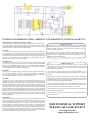
Other Available RF Products
Transmitter/Receiver Sets:
TX-99K1- 300MHz AM RF LC-based single-button transmitter with encoder
TX-99K2- 300MHz AM RF LC-based Two-button transmitter with encoder
TX-99 V3.0- 300MHz AM RF LC-based transmitter
RE-99 V3.0A- 300MHz AM RF super regenerative receiver
TX-66 V3.0- 310MHz AM RF transmitter with SAW resonator
RE-66 V3.0A- 310MHz AM RF super-regenerative receiver
Encoder/Decoder Sets:
TX-01- 12-bit encoder motherboard ( 8-bit address/4-bit data )
RE-01- 12-bit decoder motherboard ( 8-bit address/4-bit data )
RE-01_013101
Applications:
Wireless Control
Garage Door Opener
Remote Data Acquisition
Car Alarm/Keyless Entry
12-BIT DECODER
MOTHERBOARD
Operation Information
The RE-01 latching data outputs are TTL level (0 = Low = 0V,1 = High = 5V). The term
latching means that whatever data sent to the data outputs remain on the output pins until
new data are sent, even after the incoming transmission stops. Switches 9-12 must be
"on" in order to use the RE-01 data outputs. If switches 9-12 are "off", all data output
wires will be disconnected from the data pins on the decoder IC, and no data will appear
on the output wires. The momentary relay on the RE-01 board closes when a valid
address is received, and unlike the data outputs, only remains active until the incoming
transmission stops.
RE-01
Address bits are set according to the positions of switches 1-8. If an address switch is
"on", the corresponding address bit will be sent low. If an address switch is "off", the
corresponding address bit will be sent high. The RE-01 address switch settings must
match the address switch settings of the compatible encoder board, TX-01 in order to
achieve accurate data transmission.
The RE-01 accepts a serial TTL level data input. This input should be connected to the
data output on any MING receiver board (RE-66 or RE-99). Power is supplied to the
selected receiver by way of the 3-pin connector located on the RE-01.
Testing and Troubleshooting
The RE-01 is a 12-bit decoder board. It is ideal for almost any application needing a
wireless control system. When used with the TX-01 encoder motherboard, TX-99 or
TX-66 transmitter board, and RE-99 or RE-66 receiver board, the RE-01 offers 4 bits
of data providing up to 16 different codes. 8 bits of address ensure that data sent from
your transmitter/encoder is passed on to the RE-01 data outputs, and all stray data are
rejected. The 8-bit address also allows up to 256 individually addressed receivers to
be used with a single transmitter. This set works well in applications such as
gathering data from remote sensors or controlling remotely located objects such as
lights, valves, motors or just about anything else.
Specifications
ELECTRICAL
Operating Voltage: 12VDC
Operating Current:
Depends on receiver used
Frequency:
Depends on receiver used
Circuit Type:
Depends on receiver used
ENVIRONMENTAL
Operating Temp:
0°C to 40°C
Storage Temp:
-20° to 80°C
PHYSICAL
Length:
3-1/4” (82.55mm)
Width:
2-3/8” (60.33mm)
Height:
3/8” (9.53mm)
Weight:
1.2oz (.042gms)
Certain problems can arise when working with RF products. If the transmitter or receiver
boards are not accurately tuned, or possibly defective, the desired signal may never reach
its destination. At the same time, if the address of the encoder board does not match the
address of the decoder board, or either board is defective, again, the desired signal may
never reach its destination. It is sometimes very difficult to tell what the actual problem is.
The following instructions should be helpful.
The first thing to be tested are the encoder motherboard (TX-01) and decoder
motherboard (RE-01). These will become very useful in testing, and if necessary, tuning
the transmitter and receiver. To check the TX-01 and RE-01 you must remove the
transmitter and receiver from these boards. Make sure both motherboards are connected
to the same power supply, and connect the data-pin on the TX-01 to the data-pin on the
RE-01 (located on the 3-pin connector) with a piece of wire. With both addresses
matched and power applied, the Valid ID relay on the RE-01 should be closed. If the relay
is not closed, and your power supply is above 9VDC, contact your vendor and request
replacements.
Now that you have determined your TX-01 and RE-01 boards are functioning accurately,
the transmitter and receiver can be tested. Attach the transmitter to the encoder board and
apply power. Attach the receiver to the decoder board, position them about 50 feet away
from the encoder/transmitter boards, and apply power. If the address of the encoder
matches the address of the decoder, and the power supply is at least 9VDC for both the
TX-01 and RE-01, the Valid ID relay on the RE-01 should be closed. If the relay is not
closed, an attempt should be made to tune the receiver board.
The frequency of the receiver board can be modified by carefully turning the variable
capacitor located on top of the receiver board. This should be done with a plastic or
ceramic screw-driver. The variable capacitor looks a lot like a flat head screw and has a
half-turn range. This means that if you have adjusted the capacitor more than one half of a
turn in either direction, you will have gone through the entire range of the capacitor and
should have picked up the signal. Continue slowly turning the capacitor until the Valid ID
relay closes. This procedure can be repeated at various distances up to 100 feet away from
the transmitter. The guaranteed operating distance of these sets is 50 feet, but with a little
attention and a wire antenna, these boards are capable of about 100 feet. If you are unable
to achieve the guaranteed distance of 50 feet, or if you feel that tuning these boards is
beyond your ability, please contact your vendor for replacements. These boards are tuned
from the factory and should have at least a 50 foot range. Tuning is only recommended
when greater distances are required or in the event that a board appears to be defective.
GENERAL INFORMATION THAT APPLIES TO OUR REMOTE CONTROL PRODUCTS
BREAKDOWN OF A REMOTE CONTROL SYSTEM:
A remote control system is any system with controls or commands delivered to the main unit
from a distance, in this case by way of radio frequency transmission. The remote system we
will discuss includes an encoder, transmitter, receiver, and decoder. All of these parts must be
used in order to attain a complete link. See descriptions below.
ENCODER:
An encoder is a circuit in which a code or signal presented in one format can be changed to a
format compatible with the circuitry it interfaces with. In the case of the TX-01 the format
delivered by the user is a 12 bit parallel code consisting of 8 address bits and 4 data bits. This
code must be changed to a serial format in order to become compatible with the transmitter's
input. This is the job of the TX-01 encoder motherboard, or more specifically, the HT12E
encoder IC found on the TX-01 encoder motherboard.
TRANSMITTER:
A transmitter is a circuit with an output sent through the air by, sound or electromagnetic
waves at a specific frequency. In the case of the TX-99, the output is an amplitude modulated
radio frequency of 300MHz. The transmitter receives a coded signal from the encoder and
uses that signal to modulate its 300MHz carrier. In simple terms, the output of the transmitter
is an electromagnetic representation of the input data code.
RECEIVER:
A receiver is a circuit capable of accepting and processing light, sound, or electromagnetic
waves of a specific frequency. In the case of the RE-99, the 300MHz radio frequency
signal sent by the transmitter is received, and the incoming data extracted from that signal.
The extracted data is then sent out in serial format to the decoder board.
DECODER:
A decoder is a circuit in which a coded signal of a specific format (usually that of its
compatible encoder) is received and changed to a format compatible with the circuitry it
interfaces with (usually the format originally presented to the encoder is the same format used
for the output of the decoder when used in wireless systems, but not always). In the case of the
RE-01, the incoming code is a 12 bit serial format. This code must be checked to ensure that
the first 8 bits (address bits) match the address of the decoder IC. This is the job of the RE-01
decoder motherboard, or more specifically, the HT12D decoder IC found on the RE-01
decoder motherboard. If the incoming 8 bit address is correct, the last 4 bits of the 12 bit code
(data bits) are passed on to the data outputs of the RE-01, and the Valid ID relay closes and
remains closed until the incoming signal is no longer present. The 4 data bits, however, latch
and remain in whatever state they were set to by the last transmission, until they are changed
by the next transmission.
DATA CODES:
A data code is a set of numbers or letters representing some form of information. In the case of
the encoders and decoders described above, the data code consists of a combination of four 1s
and/or 0s representing 16 possible states. If a +5V signal is applied to one of the four data
lines, or if the data line is left floating ( not connected ) , this is considered a 1. If +0V (or
ground) is applied to one of the four data lines, this is considered a 0. By using different
combinations of 1s and 0s on the four data lines, 16 separate control commands can be sent.
IC’s are available, such as the 74HC154, which can turn the 4 bit data output of the RE-01
into a more user friendly output, giving you the option to select 1 of 16 different output pins to
activate per transmission. If the 4 bit data code is being sent to a micro-controller, or if less
than 4 different commands are needed, these extra IC’s are not needed.
IMPORTANT NOTE:
The bandwidth utilized on our RF modules was intended for experimental use in
applications that require only short burst transmissions. Our RF boards must be used
with their intended motherboards (TX-01 & RE-01) and cannot be used for
continuous serial data applications.
Ming Microsystem’s RF products are designed for experimental use and are not
FCC approved. It is the responsibility of the user to verify compliance with FCC
regulations on their own application and obtain an FCC approval number for the
final product which is to be marketed.
LIMITED WARRANTY
This product is warranted against manufacturing defects in materials and
workmanship for 30-days from the date of purchase. Within this period, Ming
Microsystem will, at its option, repair or replace the product, or any part thereof,
without charge for parts and labor.
This warranty does not apply in the following cases: Improper installation, misuse,
failure to follow installation and operating instructions, alteration, abuse, accident or
tampering.
Ming Microsystem is not responsible or liable for indirect, special, or consequential
damages arising out of or in connection with the use or performance of the product or
other damage with respect to any economic loss, loss of property, loss of revenues or
profit, or costs of removal, installation or reinstallation.
Except as provided herein, Ming Microsystem makes no express warranties, and any
implied warrant of merchantability or fitness for particular purpose is limited in its
duration to the duration of the written limited warranties set forth herein.
There will be charges rendered repairs to the product made after the expiration of the
aforesaid 30-days warranty period.
This warranty gives you specific legal rights and you may have other rights which
vary from state to state.
FOR TECHNICAL SUPPORT
PLEASE CALL (626) 961-6273
www.ming-micro.com
[email protected]