1
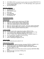
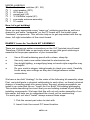
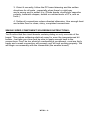
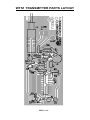
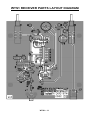
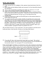
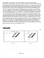
Wireless Trip Sensor Ramsey Electronics Model No. WTS1 Guard your perimeter and catch those folks trying to sneak up on you with this neat little kit. • Transmitter fits in an included PVC tube • Receiver can be 300ft. from transmitter. • Works with your laser pointer or ambient light. • Powered by any 9 - 12 VDC source. • Uses analog and digital circuitry in a simple, robust design. • Complete and informative instructions guide you to a kit that works the first time, every time. • Learn about simple RF transmitter/receiver pair. WTS1 • 1 PARTIAL LIST OF AVAILABLE KITS: RAMSEY TRANSMITTER KITS • FM10A, FM25B FM Stereo Transmitters • AM1, AM25 Transmitter RAMSEY RECEIVER KITS • FR1 FM Broadcast Receiver • AR1 Aircraft Band Receiver • SR2 Shortwave Receiver • AA7 Active Antenna • SC1 Shortwave Converter RAMSEY HOBBY KITS • SG7 Personal Speed Radar • SS70A Speech Scrambler/Descrambler • TT1 Telephone Recorder • SP1 Speakerphone • MD3 Microwave Motion Detector • TFM3 Tri-Field Meter • LC1 Inductance-Capacitance Meter RAMSEY AMATEUR RADIO KITS • HR Series HF All Mode Receivers • QRP Series HF CW Transmitters • VLF1 Low Frequency SWL Converter • QRP Power Amplifiers RAMSEY MINI-KITS Many other kits are available for hobby, school, scouts and just plain FUN. New kits are always under development. Write or call for our free Ramsey catalog. WTS1 WIRELESS TRIP SENSOR Ramsey Electronics publication No. WTS1 Rev. 1.1 January 2003 COPYRIGHT 2003 by Ramsey Electronics, Inc. 590 Fishers Station Drive, Victor, New York 14564. All rights reserved. No portion of this publication may be copied or duplicated without the written permission of Ramsey Electronics, Inc. Printed in the United States of America. WTS1 • 2 Ramsey Publication No. WTS1 Manual Price Only $5.00 KIT ASSEMBLY AND INSTRUCTION MANUAL FOR Wireless Trip Sensor TABLE OF CONTENTS Introduction to the WTS1 .................................. 4 WTS1 Circuit Description .................................. 4 “Learn-As-You-Build” Kit Assembly ................... 5 Parts List ........................................................... 6 Parts Layout Diagram ...................................... 10 Schematic Diagram......................................... 12 Assembly Steps ............................................... 14 Setup and Testing ........................................... 18 Troubleshooting Guide ..................................... 19 Ramsey Kit Warranty ....................................... 23 RAMSEY ELECTRONICS, INC. 590 Fishers Station Drive Victor, New York 14564 Phone (585) 924-4560 Fax (585) 924-4555 www.ramseykits.com WTS1 • 3 INTRODUCTION Do friends keep sneaking up behind you to make some rude noise and make you jump out of your skin? Do nosey people keep showing up uninvited and causing you to change your plans for the evening? You need a way to warn you of these visitors so you have time to prepare. You’re in luck; a way has been found! The Ramsey WTS1 will protect you! Just hide the sensor somewhere that an intruder’s shadow will pass over it and place the receiver in a convenient location nearby. When your “guest” shows up, an obnoxious alarm will warn you. No more embarrassing moments of being caught unawares. In addition to a secure perimeter, you also get the benefit of learning some basics of an RF transmitter/receiver pair. You’ll notice that two PC boards came with your kit. One is the transmitter, and one is the receiver. They are both single sided and have fairly loosely spaced parts so you shouldn’t have much trouble soldering them up. Especially not with our exquisite step by step parts placement instructions. Before we begin let us take a brief stroll down theory lane and learn a bit about RF transmitters and receivers, shall we? WTS1 CIRCUIT DESCRIPTION Before we begin dissecting the circuit, let’s have a look at the “big picture” and see what it is that we’re trying to accomplish. What we want is to have a transmitter that is sensitive to the light level around it and a receiver that sounds an alarm when alerted by the transmitter. Take a look at the schematic for the transmitter. Infrared phototransistor Q5 responds to the light falling on it. If everything is dark, Q5 is off, resistor R6 biases Q3 and Q4 on, which pulls the transmit enable pin 14 of the HT12E low. The HT12E is an encoder that sends out a code number to the receiver. This allows you to have more than one transmitter in the same area. Now take a look at the receiver schematic. The antenna wire feeds RF that comes from the transmitter into the MICRF001BN receiver IC. The MICRF001BN converts the RF to a digital signal which it sends to the HT12D decoder IC. The HT12D then compares the code number in the signal with its own code number setting. If the two numbers match, it signals the rest of the circuit to sound the alarm. + WTS1 • 4 RAMSEY Learn-As-You-Build KIT ASSEMBLY There are numerous solder connections on the WTS1 printed circuit board. Therefore, PLEASE take us seriously when we say that good soldering is essential to the proper operation of your transmitter! • • • • Use a 25-watt soldering pencil with a clean, sharp tip. Use only rosin-core solder intended for electronics use. Use bright lighting, a magnifying lamp or bench-style magnifier may be helpful. Do your work in stages, taking breaks to check your work. Carefully brush away wire cuttings so they don't lodge between solder connections. We have a two-fold "strategy" for the order of the following kit assembly steps. First, we install parts in physical relationship to each other, so there's minimal chance of inserting wires into wrong holes. Second, whenever possible, we install in an order that fits our "Learn-As-You Build" Kit building philosophy. This entails describing the circuit that you are building instead of just blindly installing components. We hope that this will not only make assembly of our kits easier, but help you to understand the circuit you’re constructing. For each part, our word "Install" always means these steps: 1. Pick the correct part value to start with. 2. Insert it into the correct PC board location. 3. Orient it correctly, follow the PC board drawing and the written directions for all parts - especially when there's a right way and a wrong way to solder it in. (Diode bands, electrolytic capacitor polarity, transistor shapes, dotted or notched ends of IC's, and so forth.) 4. Solder all connections unless directed otherwise. Use enough heat and solder flow for clean, shiny, completed connections. SINGLE SIDED COMPONENT SOLDERING INSTRUCTIONS: You’ll notice that the circuit board contains plating on only one side of the board. This makes soldering relatively easy for even the inexperienced kit builder. Just take your time and be sure to apply enough heat to the connections. Don’t be too afraid of overheating a component, most are fairly hardy and a weak connection will prevent your kit from working properly. WTS1 • 5 In all RF kits it is a good idea to keep the components as close to the board as you can and trim off the excess lengths of the component legs. This minimizes stray inductance that might throw off the frequency of some oscillator in your kit. WTS1 PARTS LIST Sort and “check off” the components in the boxes provided. We do our best to pack all our kits correctly but it is possible that a mistake has occurred and we missed a part. Note that there are 2 boards; the bigger receiver board, and the smaller transmitter board. Please note that physical descriptions of parts are for those currently being shipped. Sometimes the parts in your kit may have a different appearance but still have the same values. TRANSMITTER BOARD RESISTORS 2 470 ohm resistor [yellow-violet-brown] (R1,R2) 1 2.2K ohm resistor [red-red-red] (R5) 2 47K ohm resistor [yellow-violet-orange] (R3,R7) 1 270 ohm resistor [red-violet-brown] (R8) 2 1M ohm resistor [brown-black-green] (R4,R6) 1 10K ohm resistor [brown-black-orange] (R9) CAPACITORS 4 .001 uF ceramic disc capacitors [marked 102] (C1,C2,C3,C4) 1 10 pF ceramic disc capacitor [marked 10] (C7) 1 2 pF ceramic disc capacitors [little green marked 2.2] (C5) 1 100 pF ceramic disc capacitor [marked 101] (C6) 1 10uF electrolytic capacitor (C8) INDUCTORS 1 43 nH [air coil]] (L1) SEMICONDUCTORS Note: Chips may have other numbers and letters on them; the important numbers are those listed in brackets. 1 2 2 1 HT-12E [HT-12E] encoder (U1) 2SC2498 or 2SC2570A PNP bipolar transistor [marked C2570A or C2498] (Q1,Q2) 2N304 NPN transistor [marked 2N3904] (Q3,Q4) 2N3906 PNP bipolar transistor [marked 221334] (Q6) WTS1 • 6 1 1 1 433.42MHz SAW resonator [round metal can marked RFM R02112] Infrared phototransistor [clear T1 3/4 LED package, with a green dot on the bottom] (Q5) mini red LED (D1) MISCELLANEOUS 1 9V battery snap 1 antenna wire 1 4AA battery holder 1 PVC pipe 2 PVC endcaps 1 pushbutton switch 1 IC socket for U1 RECEIVER BOARD RESISTORS 2 270 ohm resistors [red-violet-brown] (R7,R8) 1 10K ohm resistor [brown-black-orange] (R5) 1 100K ohm resistor [brown-black-yellow] (R3) 1 470K ohm resistor [yellow-violet-yellow] (R6) 1 56K ohm resistor [green-blue-orange, may have white body] (R4) 1 68K ohm resistor [blue-gray-orange, may have white body] (R1) 1 470 ohm resistor [yellow-violet-brown] (R2) CAPACITORS 2 .01 uF ceramic disc capacitors [marked 103] (C1,C9) 3 .1 uF ceramic disc capacitors [marked 104] (C2,C8,C11,C12) 2 10 pF ceramic disc capacitors [marked 10] (C5,C6) 1 .001 uF ceramic disc capacitor [little green, marked 102] (C7) 3 10 uF electrolytic capacitors (C3,C10,C14) 1 1 uF electrolytic capacitor (C4) 1 220 uF electrolytic capacitor (C13) INDUCTORS 2 43 nH inductors [air coil] (L2, L1) SEMICONDUCTORS 1 2SC2498 PNP bipolar transistor [marked C2570 or C2498] (Q1) 1 78L05 low power 5 volt regulator [marked 78L05] (VR1) 2 74HC132N quad 2 input Schmitt trigger NAND gate [marked M74HC132B1] (U1,U4) 1 MICRF001BN receiver/data demodulator [marked MICRF001BN] (U2) 1 HT12D decoder [marked HT12D] (U3) 2 LEDs (D1, D2) WTS1 • 7 MISCELLANEOUS 2 Pushbutton switches (S1, S2) 1 mini speaker (SP1) 1 RCA jack (J1) 1 power jack (J2) 1 3.3149MHz crystal (X1) 1 pre-made antenna assembly 1 IC socket Now, let's get building! Since you may appreciate some “warm-up” soldering practice as well as a chance to put some “landmarks” on the PC board we’ll first install some “hardware” components. This will also help us to get acquainted with the updown, left-right orientation of the circuit board. RAMSEY Learn-As-You-Build KIT ASSEMBLY There are numerous solder connections on the VLF1 printed circuit board. Therefore, PLEASE take us seriously when we say that good soldering is essential to the proper operation of your transmitter! • • • • Use a 25-watt soldering pencil with a clean, sharp tip. Use only rosin-core solder intended for electronics use. Use bright lighting, a magnifying lamp or bench-style magnifier may be helpful. Do your work in stages, taking breaks to check your work. Carefully brush away wire cuttings so they don't lodge between solder connections. We have a two-fold "strategy" for the order of the following kit assembly steps. First, we install parts in physical relationship to each other, so there's minimal chance of inserting wires into wrong holes. Second, whenever possible, we install in an order that fits our "Learn-As-You Build" Kit building philosophy. This entails describing the circuit that you are building instead of just blindly installing components. We hope that this will not only make assembly of our kits easier, but help you to understand the circuit you’re constructing. For each part, our word "Install" always means these steps: 1. Pick the correct part value to start with. 2. Insert it into the correct PC board location. WTS1 • 8 3. Orient it correctly, follow the PC board drawing and the written directions for all parts - especially when there's a right way and a wrong way to solder it in. (Diode bands, electrolytic capacitor polarity, transistor shapes, dotted or notched ends of IC's, and so forth.) 4. Solder all connections unless directed otherwise. Use enough heat and solder flow for clean, shiny, completed connections. SINGLE SIDED COMPONENT SOLDERING INSTRUCTIONS: You’ll notice that the circuit boards contain plating on only one side of the board. This makes soldering relatively easy for even the inexperienced kit builder. Just take your time and be sure to apply enough heat to the connections. Don’t be too afraid of overheating a component, most are fairly hardy and a weak connection will prevent your kit from working properly. We will begin our assembly with the transmitter (the smaller board). WTS1 • 9 WTS1 TRANSMITTER PARTS LAYOUT WTS1 • 10 WTS1 RECEIVER PARTS LAYOUT DIAGRAM WTS1 • 11 WTS1 • 12 WTS1 • 13 WTS1 TRANSMITTER PC BOARD ASSEMBLY STEPS 1. Install an IC socket for U1, HT12E encoder IC. Then pop the HT12E in the socket. Make sure the notch on one end of the chip lines up with the notch on the board drawing. The IC socket is for a modification you can make to your kit that is discussed at the end of this manual. 2. Install Q4, 2N3904 transistor, at one end of U1. Be sure the flat side faces D1 like in the board drawing. 3. Install Q3, 2N3904 transistor, just to the left of Q4.Q3 and Q4 form a Darlington pair that gives the WTS1 its high sensitivity to light. 4. Install R6, 1M ohm resistor [brown-black-green], next to Q3. 5. Install R3, 47K ohm resistor [yellow-violet-orange], above Q3. 6. Install D1, red LED, just to the right of Q4. Make sure the flat edge lines up with the flat side of the drawing on the board. 7. Install Q5, infrared phototransistor, between Q4 and Q3. This is the detector that senses the ambient light level. This part has a green dot on the underside next to the shorter of the two leads. The short lead should be installed in the hole closest to Q3. 8. Install R4, 1M ohm resistor [brown-black-green], on the right side of U1. 9. Install R2, 470 ohm resistor [yellow-violet-brown]. 10. Install C6, 100 pF ceramic disc capacitor [marked 101]. 11. Install C4, .001 uF ceramic disc capacitor [marked 102], right above U1. 12. Install R9, 10K ohm resistor [brown-black-orange]. 13. Install R5, 2.2K ohm resistor [red-red-red]. 14. Install Q6, the PNP transistor [marked 221334]. Follow the PC board silkscreen for orientation of the flat side of this transistor. 15. Install R7, 47K ohm resistor [yellow-violet-orange]. 16. Install R1, 470 ohm resistor [yellow-violet-brown]. 17. Install C1, .001 uF ceramic disc capacitor [marked 102]. 18. Install C3, another .001 uF ceramic disc capacitor [marked 102]. 19. Install X1, surface acoustic wave resonator [marked RFMR02112]. This generates the 433MHz RF carrier. WTS1 • 14 20. Install Q1, the 2SC2570A or 2SC2498 transistor, next to X1. 21. Install Q2. the 2SC2570A or 2SC2498 PNP bipolar transistor, next to Q2. Q1 and Q2 drive the transmitting antenna. 22. Install L1, 43nH inductor [air coil]. 23. Install C8, 10 uF electrolytic capacitor next to L1. Observe polarity! The “+” side of the capacitor must line up with the “+” side on the board drawing. The “-” side of a capacitor is usually labeled with a band. The “+” is the other side. 24. Install C7, 10 pF ceramic disc capacitor [marked 10], adjacent to Q2. 25. Install C5, 2 pF ceramic disc capacitor [marked 2.2]. 26. Install R8, 270 ohm resistor, [red-violet-brown]. 27. Install C2, .001 uF capacitor, [marked 102]. 28. Install SW1, pushbutton switch, next to C2. 29. Install the 9V battery snap. Solder the red wire into the “+” hole and the black wire into the “-” hole. 30. Cut a 5 inch piece of the thin wire and solder one end into the antenna hole marked ANT1. 1/4 wavelength at this frequency is approximately 6.5 inches. That’s it! Now the transmitter is complete. There isn’t really any way to test it without the receiver, so….. WTS1 RECEIVER PC BOARD ASSEMBLY STEPS 1. Begin by installing S1 and S2, pushbutton switches. Line them up with the drawing on the board and seat them flush to the PC board before soldering them into place. 2. Install D1, red LED, next to S1. Line up the flat edge with the flat part of the drawing on the board. 3. Install D2 in the same way next to S2. 4. Install SP1, mini speaker, in between D1 and D2. It doesn’t have polarity; it can go in either way. 5. Install C14, 10 uF electrolytic capacitor, next to D2. Be sure to observe polarity. WTS1 • 15 6. Install R7, 270 ohm resistor [red-violet-brown]. 7. Install VR1, 78L05 voltage regulator, next to R7. It looks like a transistor and must be placed with the flat side facing in the right direction. It should face SP1. This provides 5 V power for the receiver. 8. Install C11, .1 uF ceramic disc capacitor [marked 104], on the left side of SP1. 9. Install R8, 270 ohm resistor [red-violet-brown], next to C11. 10. Install R5, 10K ohm resistor [brown-black-orange], down and to the left of R5. 11. Install U1, 74HC132N quad 2 input Schmitt trigger NAND gate [marked 74HC132B1], next to R5. Be sure the notch at one end of the IC lines up with the notch on the drawing on the board. This chip contains logic gates that control the alarm. 12. Install C13, 220 uF electrolytic capacitor. WARNING: If the one you get is a red/brown can, be EXTRA SURE that it is in the right way. These tend to explosively disassemble if put in backwards. Plus and minus are both marked on the top of these. 13. Install an IC socket for U3, HT12D decoder IC, under U1. Then place the HT12D in the socket. Again, watch the notch alignment. 14. Install R1, 68K ohm, resistor [blue-gray-orange], next to U3. 15. Install C4, 1 uF electrolytic capacitor across from R1. Watch the polarity! 16. Install X1, 3.3149MHz crystal next to C4. It can go in either way. X1 is part of the clock oscillator for U2, MICRF001BN 17. Install U2, MICRF001BN receiver/data demodulator IC, next to C3. This receives the RF transmission from the transmitter board, removes the carrier wave, and outputs a digital signal. 18. Install L1, 43 nH inductor [air coil]. 20. Install C5, 10 pF ceramic disc capacitor [marked 10]. 21. Install C2, .1 uF ceramic disc capacitor [marked 104]. 22. Install C8, .1 uF ceramic disc capacitor [marked 104]. 23. Install R3, 100K resistor [brown-black-yellow], next to C5. 24. Install U4, another 74HC132N quad 2 input Schmitt trigger NAND gate, with yet more logic gates to control the alarm [marked M74HC132B1], next WTS1 • 16 to C8. Once again, line up the notch. 25. Install C12, .1 uF ceramic disc capacitor [market 104], above U1 26. Install R6, 470K ohm resistor [yellow-violet-yellow], next to C12. 27. Install C10 10 uF electrolytic capacitor, at the end of U1. Watch polarity again. 28. Install R4, 56K resistor [green-blue-orange], under U1 29. Install C9, .01 uF ceramic disc capacitor [marked 103], under R4. 30. Install Q1, the last 2SC2570 or 2SC249B PNP bipolar transistor [marked C2498], under R3. The flat face should face R3. 31. Install C1, .01 uF ceramic disc capacitor [marked 103], left of Q1. 32. Install R2, 470 ohm resistor [yellow-violet-brown], under C1. 33. Install C7, .001 uF ceramic disc capacitor [marked 102], next to Q1. 34. Install L2, 43 nH inductor [air coil], next to C7. 35. Install C6, 10 pF ceramic disc capacitor [marked 10]. 36. Install J1, RCA jack at the bottom of the board, Don’t be afraid to gob up the solder on this one. It will give the contacts extra mechanical strength. 37. Install J2, power jack, at the lower right hand corner of the board. Go ahead and gob again. 38. Install C3, 10uF electrolytic capacitor. Watch that polarity! 39. Using a scrap piece of component lead or other thin wire, install JMP1. Form the wire or lead into the form of a staple and solder it in place. That’s it! Now it’s time to test out the WTS1. WTS1 • 17 SETUP AND TESTING First, connect the 12V adapter to the receiver board and plug it into the wall. Pop 4 AAs into the battery holder and connect it to the transmitter board’s 9V connector. Turn on the transmitter by pushing the switch out. Out is on, in is off. Turn on the receiver board by pushing switch S2 in. Make sure the antenna wire on the transmitter board is routed so that it lies on the board as little as possible. It should run down the bottom of the board and hang off the end, not go over U1 and the rest of the components. Plug the antenna you made into the RCA jack on the receiver board so that it sticks up in the air. You need to set the code number that the transmitter and receiver will use. Next to U3 on the receiver board and next to U1 on the transmitter board there are a bunch of holes that look like another chip is supposed to go there. These are for a jumper to set the code number. You have 256 possible code numbers. For those of you interested in binary, the hole columns each have a number and all the columns together make up a binary number. A jumper in hole 0 is number 2^0, or 1. All you need to know is, if you only have 1 kit, put a jumper in the first set of holes and also in the first set of holes on the transmitter board. Cover the IR led on the transmitter board with your hand. The red led should light and an obnoxious noise should emanate from the speaker on the receiver board. You can push S1 to reset the alarm. If the red led lights, but there is no obnoxious noise, the receiver is not picking up the transmitter’s signal. Move the two closer together and keep trying. Also make sure the transmitter’s antenna is routed as described. Once you get it working, it’s time to decide where to place your receiver and transmitter boards. The PVC pipe we included with your kit is to put your transmitter and battery holder in, to give it a more finished look and provide some weather resistance. If you want to use this, poke the infrared phototransistor out of the hole in one of the PVC endcaps. While holding the phototransistor so it WTS1 • 18 doesn’t slip out, slide the battery holder and circuit board into the PVC tube. Be sure the antenna lies straight down the tube and doesn’t come up over the circuit board. Push the end cap onto the tube. Now push the other endcap onto the tube. For a waterproof setup you can buy some silicone RTV at the hardware store and seal up the area around the phototransistor. You can then stretch some electrical tape around the area where the endcaps meet the tube. Of course, to turn the unit on and off you’ll have to take off the tape and retape it later. A good hiding place for your transmitter is somewhere in a dimly lit area where a shadow will fall on it when someone passes between it and a distant light source. The receiver can be put anywhere that is convenient, as long as it isn’t outside of the transmitter’s range. Some experimenting will be required to find just the right spot. You can also shade the phototransistor with a little piece of tape or by having something positioned to block light from falling directly on it. This may be necessary if the transmitter is in a bright area and the alarm keeps going off TROUBLESHOOTING GUIDE If the transmitter board’s light doesn’t come on when the infrared phototransistor is completely dark, there is a construction error on the transmitter. Check U1’s orientation, and then Q1, Q2, Q3, Q4, and Q5. After that, check all the electrolytic caps, and finally that all the parts are in the right places on the board. Also be sure that U1 on the transmitter board is the HT12E, and that U3 on the receiver board is the HT12D, and that you haven’t switched them by accident. If the transmitter board’s LED comes on but the alarm doesn’t sound on the receiver board make sure the transmitter board’s antenna isn’t lying across the board as described earlier. Also try playing with the antenna by moving it around a bit, like in the old days before digital cable tv, ha ha. You can also move the transmitter and receiver closer together. The range varies a lot depending on whether you are inside or outside, and what lies between the two (walls, trees, large metal objects etc.). If all this doesn’t work check the parts orientation in the same way as you did with the transmitter board. MODIFICATIONS For the Ramsey kit builders who have now become “power builders” there is a modification you can make to juice up your WTS1. Please be aware that you may accidentally break your kit by setting up this mod, so it should be for experienced kit builders only. This mod will allow one receiver to respond to up to 4 transmitters, and indicate which transmitter activated it. In this way you could have up to 4 transmitters in different places in your house and when one WTS1 • 19 is activated, your receiver will sound its alarm and also tell you which transmitter was activated. To begin, let’s take a look at a little theory involving the operation of the transmitter and receiver. Pins 10, 11, 12, and 13 of U1 on the transmitter board are data pins that are normally grounded in the kit. When the transmitter is activated, the logic state of these pins is transmitted to the receiver and is output on the corresponding pins on U3, the HT12D decoder IC. This “copying” of logic states, (voltages) can be exploited in the following way. For example, if on the HT12E on the transmitter board, pins 10, 11, and 12 are grounded, and pin 13 is tied to +5V, the state of these pins will appear on the corresponding pins on the HT12D, on the receiver board. So pins 10, 11, and 12 will also be 0 volts, and pin 13 will be +5V. All this is useful in this way: suppose you solder a little LED between pin 13 and ground. Now when it is tripped and activated (+5V) the LED will light . So, how does all this tell you which transmitter was activated? What you do is tie a different pin to +5V for each transmitter board. One board has pin 10 tied to +5V, one has pin 11 tied, one pin 12, and one 13. Now on your receiver board solder an LED between pins 10, 11, 12, and 13 on the HT12D and ground. When a transmitter is activated, the appropriate LED will light up on the receiver board. To solder onto the pins of the ICs, carefully remove them from their sockets, bend up the pins you want to solder, and reinsert the ICs. CONCLUSION We WTS1 • 20 sincerely hope that you will enjoy the use of this Ramsey product. As always, we have tried to compose our manual in the easiest, most “user friendly” format that is possible. As our customers, we value your opinions, comments, and additions that you would like to see in future publications. Please submit comments or ideas to: Ramsey Electronics Inc. Attn. Hobby Kit Department 590 Fishers Station Drive Victor, NY 14564 or email us at: [email protected] And once again, thanks from the folks at Ramsey! WTS1 • 21 WTS1 • 22 The Ramsey Kit Warranty Please read carefully BEFORE calling or writing in about your kit. Most problems can be solved without contacting the factory. Notice that this is not a "fine print" warranty. We want you to understand your rights and ours too! All Ramsey kits will work if assembled properly. The very fact that your kit includes this new manual is your assurance that a team of knowledgeable people have field-tested several "copies" of this kit straight from the Ramsey Inventory. If you need help, please read through your manual carefully, all information required to properly build and test your kit is contained within the pages! However, customer satisfaction is our goal, so in the event that you do have a problem, take note of the following. 1. DEFECTIVE PARTS: It's always easy to blame a part for a problem in your kit, Before you conclude that a part may be bad, thoroughly check your work. Today's semiconductors and passive components have reached incredibly high reliability levels, and its sad to say that our human construction skills have not! But on rare occasions a sour component can slip through. All our kit parts carry the Ramsey Electronics Warranty that they are free from defects for a full ninety (90) days from the date of purchase. Defective parts will be replaced promptly at our expense. If you suspect any part to be defective, please mail it to our factory for testing and replacement. Please send only the defective part (s), not the entire kit. The part(s) MUST be returned to us in suitable condition for testing. Please be aware that testing can usually determine if the part was truly defective or damaged by assembly or usage. Don't be afraid of telling us that you 'blew-it', we're all human and in most cases, replacement parts are very reasonably priced. 2. MISSING PARTS: Before assuming a part value is incorrect, check the parts listing carefully to see if it is a critical value such as a specific coil or IC, or whether a RANGE of values is suitable (such as "100 to 500 uF"). Often times, common sense will solve a mysterious missing part problem. If you're missing five 10K ohm resistors and received five extra 1K resistors, you can pretty much be assured that the '1K ohm' resistors are actually the 'missing' 10 K parts ("Hum-m-m, I guess the 'red' band really does look orange!") Ramsey Electronics project kits are packed with pride in the USA. If you believe we packed an incorrect part or omitted a part clearly indicated in your assembly manual as supplied with the basic kit by Ramsey, please write or call us with information on the part you need and proof of kit purchase. 3. FACTORY REPAIR OF ASSEMBLED KITS: To qualify for Ramsey Electronics factory repair, kits MUST: 1. NOT be assembled with acid core solder or flux. 2. NOT be modified in any manner. 3. BE returned in fully-assembled form, not partially assembled. 4. BE accompanied by the proper repair fee. No repair will be undertaken until we have received the MINIMUM repair fee (1/2 hour labor) of $25.00, or authorization to charge it to your credit card account. 5. INCLUDE a description of the problem and legible return address. DO NOT send a separate letter; include all correspondence with the unit. Please do not include your own hardware such as nonRamsey cabinets, knobs, cables, external battery packs and the like. Ramsey Electronics, Inc., reserves the right to refuse repair on ANY item in which we find excessive problems or damage due to construction methods. To assist customers in such situations, Ramsey Electronics, Inc., reserves the right to solve their needs on a case-by-case basis. The repair is $50.00 per hour, regardless of the cost of the kit. Please understand that our technicians are not volunteers and that set-up, testing, diagnosis, repair and repacking and paperwork can take nearly an hour of paid employee time on even a simple kit. Of course, if we find that a part was defective in manufacture, there will be no charge to repair your kit (But please realize that our technicians know the difference between a defective part and parts burned out or damaged through improper use or assembly). 4. REFUNDS: You are given ten (10) days to examine our products. If you are not satisfied, you may return your unassembled kit with all the parts and instructions and proof of purchase to the factory for a full refund. The return package should be packed securely. Insurance is recommended. Please do not cause needless delays, read all information carefully. WTS1 • 23 WTS1 WIRELESS TRIP SENSOR Quick Reference Page Guide Introduction to the WTS1 .................................. 4 WTS1 Circuit Description .................................. 4 Parts List ........................................................... 6 Parts Layout Diagram ...................................... 10 Schematic Diagram ......................................... 12 Troubleshooting Guide ..................................... 19 Ramsey Kit Warranty ....................................... 23 REQUIRED TOOLS • • • • Soldering Iron Ramsey WLC100 Thin Rosin Core Solder Ramsey RTS12 Needle Nose Pliers Ramsey MPP4 or RTS05 Small Diagonal Cutters Ramsey RTS04 <OR> Technician’s Tool Kit TK405 ADDITIONAL SUGGESTED ITEMS • • • Holder for PC Board/Parts Ramsey HH3 Desoldering Braid Ramsey RTS08 Digital Multimeter Ramsey M133 RAMSEY ELECTRONICS, INC. 590 Fishers Station Drive Victor, New York 14564 Phone (585) 924-4560 Fax (585) 924-4555 WTS1 • 24 www.ramseykits.com TOTAL SOLDER POINTS 164 ESTIMATED ASSEMBLY TIME Beginner .............. 6 hrs Intermediate ........ 3 hrs Advanced ............. 2 hrs