1
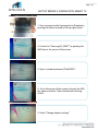
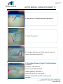
November 12
2012
This manual outlines the step-by-step installation of the Samsung
Vignette including the flooring, the wiring, the back wall, the
vignette table, the Samsung devices, the Vanguard security, and
the device configurations with supplied and required tools and
contents.
Technical Assistance
1.855.441.6965
Installation Assistance
Samantha Wheeler
T: 1.866.441.1877 x 313
C: 416.805.9357
UPON COMPLETION OF INSTALLATION
PLEASE CALL 1.855.441.6965
TO CONFIRM ALL DEVICES HAVE BEEN INSTALLED
PROPERLY AND ARE CONNECTED
Vignette
Installation
Manual
Page | 1
ADDENDUM
Section
Page
Step #
Revision
Date
Installing Vignette
Table
12
Entire Section
(Original Page
14)
MOVED:
Section moved before
installing and connecting
Back Wall, Smart TV and
Setting up Network
Oct 29
Connecting Back
Wall
14
Step 6
ADDED:
Turn Power Button “ON” on
Extender and on Power Bar
Oct 29
Samsung Device
Installation: Camera
19
Step 2
ADDED:
Insert SD Memory card into
Camera
Nov 6
Galaxy SIII: Pairing
with SMART TV
28
Step 11
REMOVED: DNS #2
Nov 6
Tablet 2: Pairing with
SMART TV
30
Step 11
Network Prefix Length: 24
ADDED: Must key in
manually
REMOVED: DNS #2
Nov 6
Camera: Wireless
Set-up & Final Install
Steps
37
Entire Section
ADDED:
Camera Wireless Set-up
Nov 6
Attachment/Placement of
Acrylic Holder for TV Remote
Final Step: Call Technical
Assistance to confirm devices
are connected
Page | 2
TABLE OF CONTENTS
Tools & Devices
Contents
Before Beginning Installation
Determining Floor Configuration
Installing Laminate Flooring
Installing Under Floor Wiring
Installing Trim
Installing Vignette Table
Installing Back Wall
Installing SMART TV
Connecting Back Wall
Setting up Network on SMART TV
Samsung Device Installation
Tablet 2 10.1
Camera WB850F
GS III
Laptop Series 9
Connecting Vignette Table
Powering Alarm Box for Vignette Table
GS III: Pairing with SMART TV
Tablet 2: Pairing with SMART TV
Laptop Series 9: Setting up AllShare Play Account
Laptop Series 9: Pairing with SMART TV
Laptop Series 9: Setting up AllShare Play Account
Camera: Wireless Set-up & Final Install Steps
Cleaning & Final Instructions
3
4
5
6
7, 8
9
10
11
12
13
14, 15
16
17, 18
19
20, 21
22
23, 24
25, 26
27, 28
29, 30
31
32, 33
34, 35, 36
37
38
Page | 3
TOOLS & DEVICES
REQUIRED TOOLS*
1. Angle
2. Knife
3. Robertson Screwdriver #8
4. Jig Saw
5. Rubber Mallet
6. Adjustable 10” Chop Saw
7. Hole Saw
8. 2” Masking Tape
9. Flat Moving Dolly
10. Vacuum
11. Garbage Bags
12. Windex
13. Cleaning Cloths
DEVICES*
1. 60” or 75” Samsung Smart TV
2. TV Remote
3. Samsung Camera WB850F
4. Samsung Tablet 10.1
5. Samsung Galaxy S III Phone
6. Samsung Laptop Series 9
7. Samsung Audio Dock
8. Samsung Audio Dock Remote
*Store to supply
9.
*Installers to bring on-site
SUPPPLIED TOOLS*
1. Brown Magic Marker (for E Cap touch up)
2. Floor Assembly Kit
*HOLMAN to provide
Page | 4
CONTENTS
1
2
6
8
7
3
11
12
SKID CONTENTS
1. 5ft - ¼” Round Wood Trim
2. 6ft Aluminum Trim
(2-way tape on top and bottom)
3. 12ft Roll of flexible E Cap Moulding
4. 4ft Chocolate Oak Laminate Planks
5. 4ft Chocolate Oak Laminate Dado
Planks (for under floor wiring)
6. 2 – 20ft Power Extension Cords
7. 2 – 25ft Ethernet Cables
8. 1 – 25ft HDMI Cable
9. 1 – 7ft Ethernet Cable
10. Table Template Jig
11. 2 Square Block Wooden Stabilizers
12. 1 U-Shape Wooden Stabilizer
13. 6 AA Batteries
14. 1 Audio Cable
15. SD Memory Card for Camera
16. Back Wall
17. Vignette Table (with keys)
CCONTENTS
1. TV Bracket
2. 75” TV Attachments
a. 1 Wood
b. 2 Foam Standoffs
3. Acrylic Holder (TV Remote)
4. Tablet Security Bracket
5. Phone Security Bracket
6. Laptop Security Bracket
7. 2 Coupler Cables - Camera and Phone
8. 1 Coupler Cable - Tablet
9. Security Allen Kit
10. Tamper Proof Bit
11. Holman Phillips Screwdriver
10.
1
4
3
7
8
5
9
2b
10
11
Page | 5
BEFORE INSTALLATION
1. Confirm install date 1 – 2 days in advance
2. Obtain store contact name and number for day of
installation
3. Arrive to store on time
4. Wear proper attire - clean Holman shirt and pants
PLEASE NOTE: WORK AREA MUST BE
COMPLETELY CLEANED BEFORE LEAVING JOB
SITE (Please see Final Instructions/Cleaning Page 35)
Foul language and unprofessional conduct will not
be tolerated.
Questions to Ask Store Manager Before Beginning:
1. Whether flooring materials can be cut in store. If
not, ask where there may be a suitable place to cut
materials i.e. loading dock or outside back of store.
2. Whether there is garbage disposal onsite. If so, ask
if it can be used to dispose of all garbage from
installation.
3. If there is a current display in location of Samsung
Vignette find out where display is to be moved and
clear space before beginning installation.
Page | 6
FLOOR CONFIGURATION
**CONFIRM FLOOR CONFIGURATIONS ON-SITE
BEFORE BEGINNING INSTALLATION**
T-TYPE: 2 Walls & 2 Open Ends
Size: 11.5ft Sq
5ft 1/4" Round: 5 pcs
6ft Aluminum Trim: 8 pcs
12ft E Cap Roll: 2
Dado Planks: 4 | Boxes of Laminate: 8
E-TYPE: 3 Walls & 1 Open End
Size: 10ft x 12ft
5ft 1/4" Round: 7 pcs
6ft Aluminum Trim: 8 pcs
12ft E Cap Roll: 1
Dado Planks: 4 | Boxes of Laminate: 7
H-TYPE: 1 Wall & 3 Open Ends
Size: 11.5ft x 10ft
5ft 1/4" Round: 2 pcs
6ft Aluminum Trim: 7 pcs/ 3ft: 1 pc
12ft E Cap Roll: 3
Dado Planks: 4 | Boxes of Laminate: 7
Room-TYPE: 3 Wall & 1 Open End
Size: 11ft x 10ft
5ft 1/4" Round: 7 pcs
6ft Aluminum Trim: 8 pcs
12ft E Cap Roll: 1
Dado Planks: 4 | Boxes of Laminate: 7
HTI-TYPE: 1 Small Wall - 4 Open Ends
Size: 11ft x 8ft
6ft Aluminum Trim: 7 (place 2" from small wall)
12ft E Cap Roll: 4 (to be used on all sides)
Dado Planks: 4 | Boxes of Laminate: 6
Page | 7
INSTALLING LAMINATE FLOORING
1. Place aluminum trim around perimeter of space
2. Remove backing on 2-way tape on underside of
aluminum trim and apply to carpet firmly
3. Corners of aluminum trim must be square for
proper application of flooring
4. Start installing laminate planks from back left
corner making sure all planks run vertically to back
wall
5. Remove backing on 2-way tape on top side of
aluminum trim
5. Stick laminate plank on 2-way tape with tongue
facing against the wall
6. Leave a 1/8” gap between laminate and edge of
aluminum trim when sticking plank to trim
7. Laminate planks must be cut to fit each size of
flooring configurations
8. Once floor is halfway complete, prepare Dado
planks for underfloor wiring
Page | 8
INSTALLING UNDER FLOOR WIRING
1. Measure centre point of floor and add 24" to the
right of center point
3. Use this measurement for placement of Dado
Planks used for under floor wiring
2. Cut main hole at 4”L x 1.5”W using hole saw and jig
saw in 1 Dado Plank to feed wires through floor
a) For 12ft floor - cut hole at 42inches from the front
b) For 10ft floor - cut hole at 30inches from the front
end
4. Cut a 4”L x 1.5”W hole at back end of 1 Dado plank
to feed wires through floor at back of wall
5. Measure and cut Dado planks to fit length of floor
6. Temporarily tape Dado planks together using
masking tape on top of laminate of Laminate - be sure
holes are in proper locations
5. Turn Dado planks over and begin placing wires in
allotted grooves
7. Leaving a 5ft tail of wire to feed through main hole
arrange 5 cables as follows:
Page | 9
INSTALLING UNDER FLOOR WIRING
8. HDMI Cable in middle of center groove with 2
Ethernet Wires on either side
9. 1 Extension Cord in the left groove with female
end connecting to the Table (Modem)
10. 1 Extension Cord in the right groove with male
end connecting to the Table (ISP Switch)
11. Tape cables to grooves of planks with masking
tape to secure
end
12. Flip Dado planks over and feed all 5 cables
through main hole and back holef
13. Remove temporary tape on top of laminate
before installing wired planks in floor
14. Continue to intall the remaining laminate
planks until floor is complete - be sure holes are in
proper locations
Page | 10
INSTALLING TRIM
1. Cut all ¼” Round Trim and E Cap on a 45 degree
angle to be sure edges fit together at corners
2. Add ¼” Round Trim to all sides of flooring that rest
against a wall
2. Use brown magic marker to touch up visible
corners of 1/4" Round Trim
3. Add flexible E Cap Moulding to all edges of flooring
that are not directly against a wall
4. Add finishing nails to ¼” Round Trim where
necessary – at the discretion of installer
5. Vacuum entire space and floor before installing
Vignette Back Wall and Table
Page | 11
INSTALLING VIGNETTE TABLE
1. Place Table Template Jig directly on floor against
main hole sitting under 5ft wire tails
2. Peel backing on 2-way tape and stick U-Shape
Block at opposite end of wires making sure it is flush
with end of jig
3. Peel plastic protective cover off of Vignette Table
and dispose of garbage
4. Place table over template making sure U-Shape
Block is centered and positioned under right leg of
Table
5. Press inside panel of left leg to open door
6. Peel backing on 2-way tape on Square Block
Stabilizers and place in either corner
7. Wires to run under left leg of Table as shown
8. Remove Table Template Jig
Page | 12
INSTALLING BACK WALL
1. Peel plastic protective cover off of Back Wall and
dispose of garbage
2. Center Back Wall to floor and leave 2ft behind to
access wiring
3. Remove any signage on walls if visible once back
wall is in place
4. To remove angle cap on top of Back Wall use the #8
Robertson Screwdriver
5. Slide back panels up to expose powerbar and
extender to connect all under floor wiring from Vignette
to TV and back wall
Page | 13
INSTALLING SMART TV
6. Secure 2 TV brackets to back of TV using metric
bolts
7. TV hook already attached to back wall as shown
8. TV hook to be moved down to lower holes if
hanging at 75" TV
Use top holes for 50" TV
Use bottom holes for 75" TVer from GS III to Disc
Sensor
9. Note: When moving TV hook to lower holes when
hanging 75" TV be sure to add wood standoff behind
hook and foam spacers at bottom to support TV
10. TV is ready to be hung
Page | 14
CONNECTING BACK WALL
1. Plug power bar located at the back of the
Samsung Backwall into wall outlet
2. Plug Samsung Smart TV into backwall power bar
using Smart TV power cord
3. Plug Samsung Audio Dock into backwall power
bar using Audio Dock power cord.
4. Using the cables coming from under the floor at
back hole, connect to the following:
5. 2 Extensions Cords
a. Male End - Plug directly into wall outlet behind
back wall
b. Female End - Plug into Extender Power Adapter
6. Turn Power Button "ON" on Extender and on
Power Bar
7. Connect Ethernet Cable from Samsung Smart TV
(labeled LAN) to Extender (labeled LAN 1)
Page | 15
CONNECTING BACK WALL
7. Connect HDMI cord into the back of the Samsung
Smart TV. Plug into the input labeled “HDMI IN 1
(DVI)”
8. 2 Ethernet Cords
9. Connect both Ethernet Cords into back of
extender (LAN 3, LAN 4)
11. Place Audio Dock on front shelf of back wall
under TV and connect
12. Peel backing on security attachment and stick to
back of Audio Dock remote
13. Turn on Samsung Smart TV with TV remote
a. Turn on Samsung Audio Dock by holding down the
play/pause button (►ll ) until you see the icons
cycle through
b. Cycle through each icon by pushing the Function
button ( F ) until there isn’t any icons showing
anymore
Page | 16
SETTING UP NETWORK ON SAMSUNG SMART TV
1. Push “Menu” button on Samsung Smart TV
remote
2. Navigate to Network
3. Click "Network Settings"
4. Push “Start” to connect to Extenderupler from GS
III to Disc Sensor
5. Once the wired network and internet connection
is complete. Select the “IP Settings” button
6. Select “Enter manually” and type in the following
information
7. Push “Ok” to confirm
8. Push “Exit” on Samsung TV Remote to return to
main screen
Page | 17
SAMSUNG DEVICE INSTALLTION: GALAXY TABLET
2
3
1
1. Using the Tamper Proof Bit separate attached
brackets from tablet security Bracket #1
4
3. Remove plastic covering from front and back of
Tablet - Dispose of garbage
4. Slide Tablet into Bracket #1 as shown
4. Replace Bracket #3 using same Tamper Proof
screws
5. Using the left post for the Tablet – separate Disc
Sensor from Retractor
6. Peel backing from Adhesive Pad on Disc Sensor
and stick to Tablet as shown. Make sure sensor is
flush to top of slot.
Page | 18
SAMSUNG DEVICE INSTALLTION: GALAXY TABLET
7. Replace Bracket #2 using same Tamper Proof
screws making sure hole for Disc Sensor Boot is not
covered
8. Place Coupler end that powers Tablet into slot in
Bracket #3
9. Insert Coupler end into Tablet socket and secure
Bracket #3
10. Plug Retractor back into Disc Sensor
11. Using Holman screwdriver attach Disc Sensor Boot
(Cap) to Disc Sensor
12. Plug Coupler from Tablet to Disc Sensor
14. Tablet is ready to be placed onto left post
Page | 19
SAMSUNG DEVICE INSTALLATION: CAMERA
1. Insert battery into camera
2. Insert SD memory card into camera
3. Use the middle post for camera and separate Disc
Sensor from Retractor
4. Peel backing from Adhesive Pad on Disc Sensor as
shown above and stick to bottom right of camera
5. Be sure the Coupler input is facing to the right of
camera and secure Disc Sensor using Security Allen
Key
6. Plug Retractor back into Disc Sensor
7. Using Holman screwdriver attach Disc Sensor Boot
(Cap) to Disc Sensor
8. Plug Coupler from Camera to Disc Sensor
9. Camera is ready to be placed on middle post
NOTE: Camera does not require ALLSHARE Play
Account set-up
Page | 20
SAMSUNG DEVICE INSTALLATION: GS III
1
2
3
1. Using the Tamper Proof Bit separate the custom
metal GS III bracket as shown
2. Insert battery into phone
3. Remove plastic protective cover from front and
back of phone
4. Slide GS III Phone into Bracket #2
5. Screw Bracket #1 using same Tamper Proof
6. Using the right post for the GS III - separate Disc
Sensor from Retractor
7. Peel backing from Adhesive Pad on Disc Sensor and
stick to back of GS III making sure the top of Disc
Sensor is flush with bracket
8. Screw middle bracket into large bracket making
sure Boot screw hole is not covered
Page | 21
SAMSUNG DEVICE INSTALLATION: GSIII
9. Plug Retractor into Disc Sensor
10. Using Holman screwdriver attach Disc Sensor
Boot (Cap) to Disc Sensor
11. Plug Coupler from GS III to Disc Sensor Plug
Coupler from GS III to Disc Sensor
12. GS III is ready to be placed onto right post
Page | 22
SAMSUNG DEVICE INSTALLATION: LAPTOP
1. Loop security lasso through holes in bracket and
feed through table
2. Peel backing on 2-way tape of security bracket
3. Stick security bracket to bottom of laptop at rear so
lip sits at edge of laptop
4. Remove backing on sensor pad and secure to
taptop
5. Loop security lasso that is fed through table around
red screw on security device in table and secure with
security allen key as shown
Page | 23
CONNECTING SAMSUNG VIGNETTE TABLE
1. Inside the Vignette Table
2. Use cables from main hole under floor
3. Run cables up inside of Table leg to connect the
following:
a. Connect HDMI Cable into back of computer
b. Connect 1 Ethernet Cable to Plug-in switch
Page | 24
CONNECTING SAMSUNG VIGNETTE TABLE
c. Connect other Ethernet Cable into back of
Computer
d. Plug male end of extension cord into Reset Swtich
labeled "1"
e. Plug female end of other extension cord into male
end of the UPS
4. Power on Device
Turn on all power to Samsung Vignette Table by
holding down power button to the UPS located in the
left leg of table
Page | 25
POWERING ALARM BOX FOR VIGNETTE TABLE
Accessories Required:
Set of Keys & 6 AA Batteries
1. Carefully open the undercarriage of the Samsung
Vignette and locate the Alarm Box
2. Remove screw that holds the Alarm box cover
down
3. Insert 6 AA Batteries into the Alarm Box
4. Close the Alarm box and screw it back down
5. Plug all the security posts and the power adapter
into the alarm box
Page | 26
POWERING ALARM BOX FOR VIGNETTE TABLE
6. Take the silver keys attached and turn the Alarm
box to the “ON” position
7. Make sure power is connected to the Vignette
Table
**DO NOT LEAVE KEY IN ALARM BOX**
8. Once the key is turned to the "ON" position,
remove the key and hand it off to site manager
9. If key is not removed, it may switch to "OFF"
position and set Alarm Box off
TROUBLESHOOTING
Condition Response
No LEDs are illuminated on the devices in the
Samsung Podium Base
Alarm Box beeps once approximately every
15 seconds.
Alarm Box beeps twice approximately every
15 seconds.
Response
1. Make sure everything is correctly
plugged in.
2. Check the AC outlet that the vignette
is plugged into to ensure power is
available.
Batteries are low or there no batteries
installed in the Alarm Box. Replace with 6x AA
batteries.
Alarm is in the “OFF” position. Check that the
key on the Alarm Box is in the “ON” position.
Key can only be removed when in the “ON”
position.
Page | 27
GALAXY SIII: PAIRING WITH SMART TV
1. Power on TV with remote control
2. Push the “Source” button on the remote control to
navigate to the correct source “HDMI1/DVI.
3. Turn on Galaxy s III with button located on the right side
of the phone
4. Using the Galaxy s III set up the network connection to
the extender
5. Main Menu > Apps
6. Select “Settings”
7. Select “Wifi Settings”
Page | 28
GALAXY SIII: PAIRING WITH SMART TV
8. Select the Wifi Network “SamsungAP_2GEXT”
9. Password = “BnQ29P65”
**Check “Show advanced options”**
10. Under Advanced Options switch IP settings from
“DHCP” to “Static”
11. Fill out the following information for the IP settings:
IP Address: 192.168.0.18
Gateway: 192.168.0.1
Network prefix length: 24
DNS 1: 192.168.0.1
12. Select “Connect” to connect to Samsung AP
Testing:
1. Run "Gallery" App on mobile
2. Select one of images you want to be displayed
3. Press icon and select the TV from the list
Page | 29
TABLET 2: PAIRING WITH SMART TV
1. Power on TV with remote control
2. Push the “Source” button on the remote control to
navigate to the correct source “HDMI1/DVI
3. Turn on Galaxy Tab with button located on the top
left side of the tablet
4. Using the Galaxy Tab set up the Network
connection to the extender.
5. Main Menu > Apps
6. Select “Settings”
7. Select "Wi-Fi Settings"
Page | 30
TABLET 2: PAIRING WITH SMART TV
8. Select the Wifi Network “SamsungAP_2GEXT”
9. Enter Password: “BnQ29P65”
10. Select “Show advanced options” and switch IP
settings from “DHCP” to Static”
11. Scroll down to “IP Address” and fill out the
following information:
IP Address: 192.168.0.17
Gateway: 192.168.0.1
Network prefix length: 24 (Type in manually even if it
appears to be entered - field is empty until keyed in)
DNS 1: 192.168.0.1
12. Select “Connect” to connect to Samsung AP
Page | 31
TABLET 2: SETTING UP ALLSHARE PLAY ACCOUNT
1. Main Menu > Apps
2. Select “AllShare"
3. For testing purposes select an image from the
“Photos” folder
4. Once the image is chosen, select TV as the playback
device
5. Menu option will load on Samsung Smart TV in
bottom left corner. Select “Allow”
Page | 32
LAPTOP SERIES 9: PAIRING WITH SMART TV
1. Turn on power to the Samsung Series 9 laptop by
pushing the button located in the top right corner
2. Connect to “SamsungAP_2GEXT” by pushing the
WiFi bars in the corner of the screen
3. Type in network password “BnQ29P65”
4. Go to the corner of the screen and push the WiFi
bar again and select “Open Network and Sharing
Center”
5. Select “Change adapter settings”
Page | 33
LAPTOP SERIES 9: PAIRING WITH SMART TV
6. Right click on “Wireless Network Connection"
7. Select "Properties"
8. A window will open up. Select Internet Protocol
Version 4 and push properties
9. A window will open up. Select “Use the following
IP Address”
IP Address: 192.168.0.19P address: 192.168.0.19
Subnet mask: 255.255.255.0
Default gateway: 192.168.0.1
Preferred DNS server: 192.168.0.1
10. Once completed, push okay and close all
windows.
Page | 34
LAPTOP SERIES 9: SETTING UP ALLSHARE PLAY ACCOUNT
1. Open up Internet Explorer and go to the following
web address.
http://www.samsung.com/global/allshare/pcsw/
2. Download the Allshare Program
3. Once the download link has been clicked a pop up
will show up on the bottom of the webpage. Select
“Run” and start the installation.
4. A window will pop up asking to make changes to
the computer. Select “Yes”
5. Start installation by choose the language “English
(United States)”. Push “OK”
6. Check the “Accept the terms of the license
agreement” and push next
Page | 35
LAPTOP SERIES 9: SETTING UP ALLSHARE PLAY ACCOUNT
7. When the installation is completed, hit “Finished”
8. Automatically the Allshare program will start up by
opening “Connection Setting Wizard”
9. Make sure the Samsung Smart TV is on before
hitting “Next”
10. Click "Next"
11. Select the Samsung Smart TV and hit “Connect”
Page | 36
LAPTOP SERIES 9: SETTING UP ALLSHARE PLAY ACC
11. Hit “Complete” and the Samsung Series 9 Laptop
has successfully connected to the Samsung Smart TV
12. To test the device. Select as many photos from the
“Pictures” folder and select “Play on another device”.
13. The Samsung Smart TV will show up. Select the
Samsung TV
14. A pop up will show up on the bottom left corner
of the Samsung Smart TV. Select “Allow”
15. Double check all devices to be sure all are
connected and in working order
16. Once everything is double checked and
installation is complete please follow cleaning
instructions as outlined on the next page
Page | 37
CAMERA: WIRELESS SETUP & FINAL INSTALL STEPS
1. To set-up wireless connection for Camera
PLEASE CALL TECHNICAL ASSISTANCE
1.855.441.6965
2. Makse sure all wiring has been neatly placed and
replace back panels by sliding into back wall
3. Using #8 Roberston Screwdriver screw angle cap
back in with screw
4. Once back panels are secured stick TV Remote
Acrylic Holder to top left corner of back panels as
shown (making sure it is not visible from front of
display)
ONCE INSTALLATION IS COMPLETE
PLEASE CALL TECHNICAL ASSISTANCE
1.855.441.6965 TO CONFIRM ALL DEVICES HAVE
BEEN INSTALLED PROPERLY AND ARE CONNECTED
Page | 38
CLEANING & FINAL INSTRUCTIONS
Cleaning Instructions
1. Make sure all protective plastic has been removed
from contents and devices
2. Gently wipe down any dirt, dust, and fingerprints
on contents and devices
Please be cautious of sharp edges will cleaning
(Ensure not to use too much pressure when
cleaning TV Screen to ensure there is no damage)
3. ALL garbage including skid and Table Floor Jig to
be disposed of
PLEASE NOTE: WORK AREA MUST BE
COMPLETELY CLEANED BEFORE LEAVING JOB
SITE AS HOLMAN WILL BE NOTIFIED IF THIS IS
NOT THE CASE
Final Instructions
1. Voluntary Bag Check: All installers must notify
Store Manager upon leaving and present/open their
tool bags voluntarily for a bag check.
2. Device Installation Kit: Please provide the Store
Manager with:
a. Security Allen Key
b. HOLMAN Branded Phillips Screwdriver
c. Tamper Proof Screwdriver
d. Security 2-Prong Bit
before leaving the store.
3. Please complete Sign-off Sheet with photos and
return to Samantha Wheeler at Holman
November 12
2012
Technical Assistance Centre
1.855.441.6965
Tablet &
Series 9
Configuration
Page | 1
TABLE OF CONTENTS
FILE TRANSFER TO TAB2 10.1
INSTALLATION OF SURELOCK
COPYING MEDIA TO TAB2 10.1
COPYING MEDIA TO THE SERIES 9 NOTEBOOK
SERIES 9 POWER OPTIONS
2
4
15
20
24
Page | 2
FILE TRANSFER TO TAB2 10.1
1. Retrieve the USB adapter
for the Tablet and connect
it to the Series 9 Notebook
2. Insert the supplied USB key
into the Series 9 Notebook,
then click “Open folder to
view files”
Page | 3
FILE TRANSFER TO TAB2 10.1
3. Copy the following three files;
samsunglogo1280x800.jpg,
surelock.apk and
surelock.settings (hold the ctrl
key and click on the three
files), then click ctrl-c to copy.
4. Locate GT-P5113, expand this
and paste the three files within
the download folder, by using
ctrl-v
Page | 4
INSTALLATION OF SURELOCK
5. From the Home screen, click the
icon in the upper right corner
6. Click on “Settings” icon
Page | 5
INSTALLATION OF SURELOCK
7. Click on “Security”, then ensure that
Unknown sources is checked.
8. Once complete, click the “back arrow”
9. Select “My files”
Page | 6
INSTALLATION OF SURELOCK
10. Expand the Root
directory>sdcard>Download directory.
Click on SureLock.apk to install.
11. Click on “Install”
Page | 7
INSTALLATION OF SURELOCK
12. Once installation is complete, click
“Open”
13. Click “Ok, Got It!”
Page | 8
INSTALLATION OF SURELOCK
14. Check the box “Use by default for this
location”, then click on SureLock
15. Click on “Accept”
Page | 9
INSTALLATION OF SURELOCK
16. Click “Ok”
17. Tap the SureLock logo 5
times, password window
will open, type “0000”
and click “ok”
Page | 10
INSTALLATION OF SURELOCK
18. Click on “About SureLock”
19. Click on “Activate”,
then enter the code of
“458789”, then click
activate.
Page | 11
INSTALLATION OF SURELOCK
20. Once activated, click “OK”, then click
“Done” at the bottom of the screen.
21. Select
“Import/Export
Settings”
Page | 12
INSTALLATION OF SURELOCK
22. Click on “Import From File”. Then click
the green icon to select the proper file.
23. Click on “Download”
Page | 13
INSTALLATION OF SURELOCK
24. Select “SureLock settings”
25. Click on “OK”
Page | 14
INSTALLATION OF SURELOCK
26. Settings will then import, click “Done”,
once complete. This will bring you back
to the main menu, click “Done” again.
27. The following screen should appear if
SureLock was properly configured.
Page | 15
COPYING MEDIA TO TAB2 10.1
28.From the USB key, double-click on the
folder called “Low Res_2012 Audio
Demo Files”
29. Copy all the content from the
folder called “Low Res_2012 Audio
Demo Files” by selecting all (CTRL
+ A) and copying the files (CTRL +
C).
Page | 16
COPYING MEDIA TO TAB2 10.1
30. Navigate to the Tablet, GT-P5113,
and open the music folder.
31. Paste these files within the Music
folder, ctrl-v
Page | 17
COPYING MEDIA TO TAB2 10.1
32.From the USB key, double-click on the
folder called “NX Pictures” folder
33. Copy all the content from the folder
called “NX Pictures” by selecting all
(CTRL + A) and copying the files (CTRL
+ C).
Page | 18
COPYING MEDIA TO TAB2 10.1
34. Copy these files to the tablet>Pictures
directory, hit ctrl-v to paste these in
the folder
35.From the USB key, double-click on the
folder called “Movies” folder
Page | 19
COPYING MEDIA TO TAB2 10.1
36. Copy all the content from the folder
called “NX Pictures” by selecting all
(CTRL + A) and copying the files (CTRL
+ C).
37. Copy these files to the tablet>Movies
directory, hit ctrl-v to paste these in
the folder
Page | 20
COPYING MEDIA TO SERIES 9 NOTEBOOK
38.From the USB key, double-click on the
folder called “Low Res_2012 Audio
Demo Files”
39. Copy all the content from the folder
called “Low Res_2012 Audio Demo
Files” by selecting all (CTRL + A) and
copying the files (CTRL + C).
Page | 21
COPYING MEDIA TO SERIES 9 NOTEBOOK
40. Next, paste (CTRL + V) all the content
into the “Music” folder located on the
left hand sidebar under “Library”
41. From the USB key - Copy all the
content from the folder called
“Movies” by selecting all (CTRL + A)
and copying the files (CTRL + C).
Page | 22
COPYING MEDIA TO SERIES 9 NOTEBOOK
42. Next, paste (CTRL + V) all the content
into the “Videos” folder located on
the left hand sidebar under “Library”
43. From the USB key - Copy all the
content from the folder called
“Pictures” by selecting all (CTRL + A)
and copying the files (CTRL + C).
Page | 23
COPYING MEDIA TO SERIES 9 NOTEBOOK
44. Next, paste (CTRL + V) all the content
into the “Pictures” folder located on
the left hand sidebar under “Library”
Page | 24
SERIES 9 POWER OPTIONS
45.This portion of the guide is devote to change the settings on the
PC running Windows 8
•Type “power options” anywhere on the Start screen.
•Select “Settings” on the right pane
•An options window will automatically open up, click on Power Options
Page | 25
SERIES 9 POWER OPTIONS
46.Select “Choose when to turn off the display”
•Then switch all the presets to say “Never” (All 6 selections need to be changed)
Page | 26
SERIES 9 POWER OPTIONS
47.Select “Choose what closing the lid does”
•Then switch all the presets to say “Do Nothing” (All 4 selections need to be changed)