1
No.
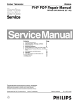
HITACHI
TA 007
42HDF39
SERVICE MANUAL
Caution
Be sure to read this manual before servicing. To ensure safety from fire, electric shock, injury, harmful
radiation and materials, various measures are provided in this Plasma Monitor.
Be sure to read cautionary items described in the manual before servicing.
These servicing instructions are for use by qualified service personnel only. To reduce the risk of electric
shock, do not perform any servicing other than that described in the operating instructions unless you are
qualified to do so.
Service Warning
1. Since the Panel Module and the front Filter are made of glass, handling the broken Module and Filter
carefully and with caution in order not to receive injury.
2. Replacement work should be started after the Panel Module and the AC/DC Power supply have
become sufficiently cool.
3. Special care should be taken when working near the display area in order not to damage its surface.
4. The Panel Module should not be touched with bare hands in order to protect its surface from
blemishes and damage.
5. It is recommended that you use clean soft gloves during the replacement work in order to protect not
only the display area of the Panel Module but also yourself.
Contents
Updated 3/24/06
1. Features -------------------------------------------3
8. Connection diagram ---------------------------- 29
2. Specifications ------------------------------------4
9. Wiring diagram ----------------------------------- 30
3. Component Names -----------------------------5
10. Basic block diagram --------------------------- 31
4. Service points ------------------------------------7
11. Printed wiring board diagram ---------------- 32
5. Adjustment ----------------------------------------8
12. Disassembly diagram ------------------------- 39
6. Troubleshooting --------------------------------13
13. Replacement parts list ------------------------ 41
7. Block diagram ---------------------------------- 27
SPECIFICATIONS AND PARTS ARE SUBJECT TO CHANGE FOR IMPROVEMENT.
Plasma Monitor
Ver. TA 007.2
1
Updated 1/31/07
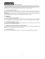
CAUTION FOR SAFETY
Please read this page before repair the monitor.
The following safety precautions are designed to help you stay safe and prevent accidents during the repair
work.
z
z
Please take note of these cautionary flags.
Warning
This means "Potential to sustain injury or even death."
Caution
This means "Potential to sustain breakage or irreparable damage."
Also note these cautionary icons
This means "CAUTION"
This means "MUST"
This means "POTENTIAL ELECTRIC
SHOCK"
This means "DO NOT"
WARNING
Follow instructions.
Must use same types of wires and components.
The cabinet, chassis, and labels are parts
The Monitor uses special tubes and tapes
that require attention. You must follow the
made from insulated materials. Moreover,
caution notes and safety instructions
some materials are kept from making
presented throughout this User Manual to
contact with the PWB for the sake of
prevent damage to them or injury to
safety.Internal leads are kept from hot
yourself.
parts or high voltage parts by means of
clamps or other measures. As such, you
must restored these parts to their original
Prevent electric shock.
conditions in order to prevent electric
Exercise caution while working on the
shock or fire.
device as the Monitor contains high
voltage parts and power supply.It is
possible to sustain severe injury or death Perform safety check when done.
if you accidentally touch the wrong
Every part (such as removed screws,
parts.You must disconnect the power
components, and wiring) must be
supply while servicing, reassembling, or
restored to their prior conditions after
change parts. If you touch a live
servicing.Be sure to check everything
connection it is possible to sustain severe
that was repaired for damage or
injury or death.
mistakes. Also measure the insulated
impedance with a meg-ohm meter to
Use recommended components.
confirm that the impedance value is more
Use only the recommended components
than 4M ohm.If the impedance value is
or componentst that structurally identical
less than 4M ohm, then electric shock or
to the originals. This is to ensure safety
fire may result.
and reliability. Pay special attention to
parts in the parts list and circuit diagrams
Do not try to check the HDCP code and
. If you use
marked with
combination circuit.
non-recommended components, then
Never remove the shield case protecting
electric shock or fire may result.
the HDCP code and combination circuit.
2
PRECAUTIONS
z
Cleaning the monitor's plasma screen panel
Before cleaning the monitor, turn it off and disconnect the power plug from the power outlet. To prevent
scratching or damaging of the plasma screen face, do not knock or rub the surface with sharp or hard objects.
Clean the screen with a soft cloth moistened with warm water and dry with a second soft cloth. If it is not
enough, then use a cloth with mild detergent. Do not use harsh or abrasive cleaners.
z
Cleaning the monitor's cabinet
Use a soft cloth to clean the monitor's cabinet and control panel. When excessively soiled, dilute a neutral
detergent in water, wet and wring out the soft cloth in it, gently clean the cabinet, and then wipe it down with a
dry soft cloth.
Never use acid/alkaline detergents, alcoholic detergents, abrasive cleaners, powder soaps, OA cleaners, car
wax, glass cleaners, and so on. They will cause discoloration, scratches or cracks.
1. Features
z
High definition Plasma display panel
The 42-inch color plasma display panel, with a resolution of 1024 (H) x 1024(V) pixels, creates a widescreen
picture. This panel features a thin form factor and can be hung on a wall with an optional wall mounting kit.
z
High Performance Digital Processor
This panel displays a wide range of personal computer signals from 640 x 400 VESA, 640 x 480 VGA to 1024
x 768, 1280 x 1024 XGA.(RGB Analog input).
z
Easy-to-use remote control and on-screen display system
The included remote control operates all Monitor functions. Futhermore, the on-screen display system shows
the status of the control settings in an easy-to-view fashion.
z
Power saving system
When connected to a VESA DPMS-compliant PC, the monitor cuts its power consumption while idle.
3
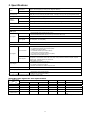
2. Specifications
Panel
Display
dimensions
Approx. 42inches (922 (H) x 522 (V) mm, diagonal 1059mm)
Resolution
1024 (H) x 1024 (V) pixels
Net dimensions
1036 (W) x 773 (H) x 300 (D) mm (With stand);1036 (W) x 713 (H) x 121 (D) mm (Without stand)
Net weight
41 kg (With stand);33.6 kg (Without stand)
Ambient
conditions
Temperatur
Operating: 0°C to 40°C, Storage: -15°C to 60°C
Relative umidity
Operating: 20% to 80%, Storage: 20% to 90% (non-condensing)
Power supply
AC100 - 240V, 50/60Hz
Power consumption/at standby
<350W / <1W
Audio output
Built in 10W + 10W (8 Ω) speakers
(RGB input)
Input signals
Input terminals
‧ANALOG RGB input terminal (D-sub 15-pin)
‧ANALOG RGB/HDMI audio input terminal (3.5mm Stereo Mini Jack)
Video signals
0.7 Vp-p
Sync signals
H/V separate, TTL level [2kΩ ]
H/V composite, TTL level [2kΩ ]
Recommended signal
25 modes
(Video input)
Input terminals
Input signals
Video signals
Output Signal
Recommended signal
‧COMPOSITE VIDEO input terminal (RCA)
L/R COMPOSITE AUDIO input terminal (RCA)
‧S-VIDEO input teminal (RCA)
L/R S-VIDEO AUDIO input terminal (RCA)
‧Y-PB/CB PR/CR input terminal (RCA)
L/R Y-PB/CB PR/CR AUDIO input terminal (RCA)
‧HDMI input terminal (HDMI 19-pin)
Composite video: PAL, SECAM, NTSC3.58, NTSC4.43
Component - YCBCR/YPBPR video: 480i, 576i, 480p, 576p, 1080i/50, 1080i/60, 720p/50, 720p/60
S-Video: PAL, SECAM, NTSC4.43, NTSC3.58
HDMI: HDMI input signal
‧SUBWOOFER output terminal (RCA)
‧TV VIDEO output terminal (RCA)
‧L/R AUDIO output terminal (RCA)
‧OPTICAL OUT DIGITAL AUDIO output terminal
9 modes
(TV RF input)
‧ANALOG RF input terminal (NTSC)
‧DIGITAL RF input terminal (ATSC)
It takes at least 30 minutes to attain the maximum picture quality.
Input signals
z
Input terminals
Applicable video signals for each input terminal
Signal Type
Terminal
RCA
Composite Video
S-Video
Component
HDMI
D-sub
DVD/STB
RGB
ANALOG RGB
{
HDMI
COMPOSITE
S-VIDEO
Y-PB/CB PR/CR
Remarks
{
{
{
1080i/720p/576p/576i/480p/480i
{
inputs.
({: Avaliable)
4
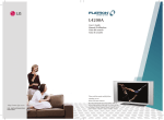
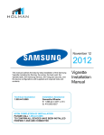
3. Component names
z
Main unit
Control panel
z
z
Al Adjustment buttons are located on the bottom of
the control panel
Indications for each button's function can be found
on the inside of the control panel cover.
1. POWER
2. UP S
3. DOWN T
4. VOL X
4. RIGHT X
5. VOL W
5. LEFT W
6. INPUT
6. EXIT
7. MENU
7. SELECT
Normal Button Action
Button Action when MENU engaged
Power lamp
Remote-control receiver
Main power switch
The main
power switch is
located at the
back, on the
right side.
5
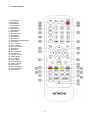
z
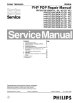
Remote Control
1. Power Button
2. Mute Button
3. Recall Button
4. Quick Buttons
5. PC Buttons
6. Video Buttons
7. NTSC Buttons
8. DTV Button
9. Numbers Button
10. RTN Button
11. Exit Buttons
12. Menu Button
13. Up/Down/Left/Right Button
14. SEL Button
15. Ch +/- Button
16. Vol +/- Button
17. DTV Menu Button
18. Back Button
19. OK Button
20. Fav. ch. Button
21. Info Button
22. PC ADJ. Button
23. Freeze Button
24. C.C. Button
25. Aspect Button
26. P. Mode Button
27. Zoom-/+ Button
28. MTS Button
29. PIP Swap Button
30. PIP Input Button
31. Sleep Button
6
4. Service points
z
Lead-free solder
This product uses lead-free solder (unleaded) to help protect the environment. Please read these instructions
before attempting any soldering work.
Caution: Always wear safety glasses to prevent fumes or molten solder from getting into
the eyes. Lead-free solder can splatter at high temperatures (600℃).
Lead-free solder indicator
Printed circuit boards using lead-free solder are engraved with an "F."
Properties of lead-free solder
The melting point of lead-free solder is 40-50℃ higher than leaded solder.
Servicing solder
Solder with an alloy composition of Sn-3.0Ag-0.5Cu or Sn-0.7Cu is recommended. Although servicing with
leaded solder is possible, there are a few precautions that have to be taken. (Not taking these precautions
may cause the solder to not harden properly, and lead to consequent malfunctions.)
Precautions when using leaded solder
z
Remove all lead-free solder from soldered joints when replacing components.
z
If leaded solder should be added to existing lead free joints, mix in the leaded solder thoroughly after the
lead-free solder has been completely melted (do not apply the soldering iron without solder).
Servicing soldering iron
A soldering iron with a temperature setting capability (temperature control function) is recommended.
The melting point of lead-free solder is higher than leaded solder. Use a soldering iron that maintains a high
stable temperature (large heat capacity), and that allows temperature adjustment according to the part being
serviced, to avoid poor servicing performance.
Recommended soldering iron:
z
Soldering iron with temperature control function (temperature range: 320-450℃)
Recommended temperature range per part:
Part
Soldering iron temperature
Mounting (chips) on mounted PCB
320℃±30℃
Mounting (chips) on empty PCB
380℃±30℃
Chassis, metallic shield, etc.
420℃±30℃
The PWB assembly which has used lead free solder
(1) POWER/EMI PWB, AUDIO POWER PWB, RS-232 PWB, AUDIO PWB, KEY PAD PWB, IR PWB, I/O PWB,
CONNECTOR PWB, SPEAKER CONNECTOR PWB, HDMI PWB
(2) MAIN PWB
(3) ATSC BOX(Digital Tuner Module) / TUNER
(4) POWER MODULE
(5) PDP MODULE (is all lead free solder. X-SUS PWB, Y-SUS PWB, LOGIC PWB, ADDRESS PWB, SDM PWB)
7
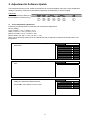
5. Adjustment & Software Update
This model has a factory mode, where the technician can access and adjust some of the color temperature
settings. The factory mode has several different appearances, depending on the input signal.
Preliminary
To access the Factory Mode, the
Plasma Monitor must be running.
z
Color temperature adjustments
Follow the procedures below to make the color temperature adjustments.
Factory setting:
Cool: x=0.268 +/- 0.01, y=0.283 +/- 0.01
Warm: x=0.314 +/- 0.01, y=0.327 +/- 0.01
Netural: x=0.285 +/- 0.01, y=0.293 +/- 0.01
Black & White: x=0.335 +/- 0.01, y=0.343 +/- 0.01
Note: That a colorimetry meter (such as a Minolta CA-200) is required to measure the actual screen color
temperature.
1.
Press MENU button on remote control to display the PDP
OSD menu.
Video
Picture Mode
Brightness
Contrast
Color
Tint
Sharpness
Color Temperature
Reset
Select to color temperature function page under VIDEO
item.
Video
Color Temperature
3.
Press SLEEP button three times to on remote control to
display the adjustment RGB parameter.
4.
Press W X to select Natural or Warm modes.
Video
Color Temperature
Cool
Red
. 0~255
Green
4. 0~255
Blue
. 0~255
2.
8
Natural
0~100
0~100
0~100
0~100
0~31
Cool
Cool
Page intentionally left blank
Page intentionally left blank
Page intentionally left blank
Page intentionally left blank
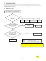
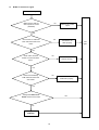
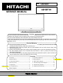
6. Troubleshooting
The flow chart shown below will help you to troubleshoot your Monitor set with it doesn’t display normally.
Each procedure offers a simple way to check for system errors. Before starting, ensure that there is a signal in
and that the Monitor is turned on.
z
Power turn on issue
Power cannot be turn on (LED does not light)
Is the input voltage
applied to Power
supply unit?
(CN61 ①③)
No
AC inlet
Power
switch
AC Fuse 5HTP10
TL.510A 250V
Filter
PWB
Yes
Check if the Power Cord
has been well connected
to TV?
No
Connect the wire
properly.
Test again
Yes
Are the voltages applied
to CN10①⑤⑥ pins and
CN11①③④⑩ pins of
Power supply unit?
No
Power supply unit
Yes
PBC-Main
(CN61) 110V
(CN10)
(CN11)
①L ③W
①+5V ⑤+12V ⑥+12V
①+5V
③+3.3V ④+3.3V ⑩+5V
Note: Voltage shown for CN10 and CN11 are at Power On State.
Power off voltages are 0V, except CN11 Pin 10, this voltage is
always present.
CH 1
13
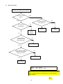
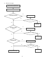
z
No sound issue
Picture is diaplayed. But no sound
Take off the back cover and
check ifl wires of the speakers
terminals have been well
connected to the PCB-Main
and speakers ?
No
Check
No sound
Yes
No
Are the voltages applied to
CN2①② of the power
supply unit?
Power supply unit
Yes
No
Are the signals applied to
P23①②③④ of the
PBC-Main?
PCB-Main or PCB-I/O
Yes
Are there signals on
the speaker terminals?
No
PCB-Audio
Yes
PCB-Speaker
Connector
Speakers
(CN2)
(P23)
14
①+15.5~16V ②GND
①NC
②L ③GND
④R
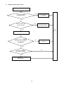
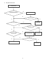
z
No picture issue
Picture is not diaplayed (LED is lighting)
Is the LED red or
green ?
Red
Green
Is it the power
saving mode ?
Is voltage applied to
CN11 ⑩(st-5v) ?
No
Yes
PCB-Main
Yes
Is the voltages of
CN10/CN11 on the
power supply unit?
Power supply
unit
Input signal
cables or
PCB-Main
No
Power supply unit
Yes
No
Are the voltages applied to
CN64①⑩ of the power
supply unit correct?
Power supply unit
Yes
Panel module
(CN10)
(CN11)
①5V ⑤⑥12V
①5V ③④3.3V
⑩st-5V
Note: Voltage shown for CN10 and CN11 are at Power On State.
Power off voltages are 0V, except CN11 Pin 10, this voltage is
always present.
CH 1
15
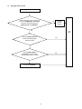
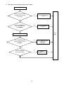
z
Remote Control doesn’t work
Remote controller doesn’t work.
Yes
Try if another Remote
Controller works?
Replace the Remote
Controller.
No
No
Check if batteries are
placed correctly?
Put new batteries to
the remote control
Yes
Test
again
Take off the back cover.
Check if the wire of PCB-IR
has been well connected to
the PCB-Main?
No
Connect the wire
properly.
Yes
Yes
Change the PCB-IR
then check if it works.
No
Change PCB-Main then connect all
wires properly.
16
z
Key pad doesn’t work
Key pad doesn’t work.
Take off the back cover and check if
the wire of PCB-Speaker connectoer
has been well connected to the
PCB-Key Pad and PCB-Main?
Connect
the wire
properly
No
Yes
Test
again
Change PCB-Key Pad and
connect all wires properly.
Check if it works
Yes
Change PCB- Speaker
connectoer and connect all
wires properly. Check if it works
No
Change the PCB-Main.
17
z
No PC signal (Analog RGB)
No PC signal.
No
Check if PC source is
working on other
display?
Check PC by PC
Service Provider
Yes
No
Check if the D-Sub cables
have been well connected
to the PDP?
Connect the D-Sub
cables properly
Yes
Test
again
Yes
Check if the signal
frequency is higher than
1024x768 ?
Adjust the signal
frequency.
Take off the back cover.
No
Change the
PCB-Main
18
z
NTSC TV source no signal
No NTSC TV Signal
Make sure the OSD TV
source option is correct
(Cable/Air)
No
Select to the correct
option
Yes
Check if the TV cable has
been well connected to the
PDP?
No
Connect the TV
cable properly
Yes
No
Check if the “Channel
Search” function has been
done?
Execute the “Channel
Search” function.
Yes
No
Check if the Assembly
PCB-Video has been well
connected?
Connect the Assembly
PCB-Video properly.
Yes
Change the NTSC Tuner
Board and check if it works.
Yes
No
Change the
PCB-Main
19
Test
again
z
DTV source no signal
Cannot receive any digital channel
Turn the TV off
No
Is the multi I/O connector
connected with scaler board
Connect it firmly
No
Is the signal received
Yes
Yes
Problem has
been resolved
No
Is the tuner connected
with antenna / cable
connector
Connect it firmly
No
Is the signal received
Yes
Yes
Problem has
been resolved
Be sure have done
the channel scan
No
Make auto scan
No
Is the signal received
Yes
Yes
Problem has
been resolved
Change the tuner module
20
z
No optical audio sound
No audio service
No
Is the multi I/O connector
connected with scaler board
Connect it firmly
No
Is the audio work
Yes
Yes
Yes
Problem has
been resolved
Is it in “MUTE” mode
No
Press “MUTE” or “VOL+”
so that audio work
No
Yes
No
Be sure this channel
was been locked
Scan this channel by
using “Manual Scan”
Problem has
been resolved
No
Is the audio work
Yes
Yes
Change the tuner module
Problem has
been resolved
21
z
No signal issue (Composite, SV, YCbCr, YPbPr)
No signal
Check if the signal source
is available and been well
connected?
No
Enable source and
connect the signal wire
properly.
Yes
Check if the PCB-I/O has
been well connected to
the PCB-Main?
No
Connect the PCB-I/O
properly.
Yes
Test
again
Take off the back cover.
No
Check if Wire Ass’y 31P
has been well connected to
PCB-Main?
Connect Wire Ass’y 31P
properly to the
PCB-Main.
Yes
No
Change the PCB-I/O
then check the signal
Yes
22
Change
PCB-Main board
z
No HDMI signal issue
No signal
Check if the signal source
is available and been well
connected?
No
Enable source and
connect the signal wire
properly.
Yes
Take off the back cover.
Check if the PCB-HDMI
has been well connected
to the PCB-Main?
No
Connect the
PCB-HDMI properly.
Test
again
Yes
Check if Wire Ass’y 31P
has been well connected to
PCB-Main?
No
Connect Wire Ass’y 31P
properly to the
PCB-Main.
Yes
Change the PCB-HDMI
then check the signal
No
Yes
23
Change
PCB-Main board
z
Software can’t be updated
Can not update software
Check if RS-232 Cable
has been well connected
to the PDP?
No
Connect RS-232
Cable properly.
Yes
Take off the back cover.
Test
again
No
Check if all wires have
been well connected to the
PCB-RS232 & PCB-Main?
Connect the wires
properly.
Yes
Yes
Change the PCB-RS232
and see if it works?
No
Change the PCB-Main.
24
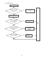
z
Power board issues
1. No power
NO POWER
NO Vs, Va, Vcc, STB
FUSE
NG
impedance check
D001
OK
NG
D001
OK
NG
STB
impedance check
Q003/Q004
check voltage
D020(k)-J051
Over 130V
Q003/Q004/R005 ect
OK
OK
impedance check
Q201
Under 130V
See NO PICTURE &
SOUND
NG
Q200/Q201/Q202/D210
ect
OK
D151, D101 etc
NG
impedance check
Q301
NG
Q301/Q302/Q303/D310
ect
IC101, R005
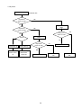
2. No picture and sound
NO PICTURE &
SOUND
NO Vs, Va, Vcc,
NG
FUSE
SEE NO POWER
OK
Vcc
OK
See NO PICTURE
NG
check voltage
D020(k)-J051
Under 130V
IC001, D601~D604, RL001,
PC001, PC003, IC002 etc
25
Over 130V
PC201, PC202, D210
etc
3. No picture
NO PICTURE
NO Vs, Va, Vcc
impedance
check Vs LINE
NG
OK
impedance
check Va LINE
Open connector
CN64
NG
impedance
check Vs LINE
OK
SW ON
OK
Open connector
CN64
NG
Va:no uprise
Vs:down after up
Q303, PC301,
PC302, D310,
etc
Vs:no uprise
Va:down after up
Q501,D510,
Q500,PC501,
PC502,etc
impedance
check Va LINE
OK
D551, D550
NG
D351
26
PDP module Va
NG
PDP module Vs
NG
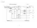
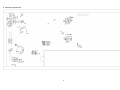
7. Block Diagram
z
Plasma Monitor
27
z
Power Module
28
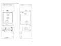
8. Connection Diagram
29
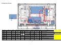
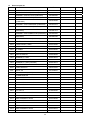
9. Wiring Block Diagram
Item
No.
1
P205
2
3
4
5
Wire
Part No.
HITACHI Part No.
Item
No.
Wire Ass’y W10/10P
E057410010
TE02294
12
P207
P203
Wire Ass’y W11/10P
E057411001
TE02292
13
P212
P201
Wire Ass’y W2/2P
E057402005
TE02291
14
P208
Wire Ass’y W9/9P
E057409002
TE02296
P9003A Wire Ass’y W4/4P
E057404011
TE02305
Wire
Part No.
HITACHI Part No.
Item
Board
FFC 50P+AI
E784650506
TE02751
D
IR Board(PWB-0874)
Part No.
HITACHI Part No.
5097659801
TE03511
Wire Ass’y W5/5P
E057405011
TE02299
E
RS-232 Board(PWB-0832)
5097643008
TS06665
P9001A Wire Ass’y W8/8P
E057408006
TE02304
F
Power/EMI Board(PWB-0905)
5097651912
TS06667
Wire Ass’y W4/4P
E057408005
-
G
Audio Power Board(PWB-0905)
5097651913
TS06666
H
Audio Board(PWB-0807)
5097639914
TS06668
15
P7002A
(This wire is included in PCB-Key pad assembly)
Parts List on page 44
6
P211
Wire Ass’y W5/5P
E057405008
TE02298
16
P215
Wire Ass’y
E057401009
TE02753
I
Speaker Connector Board(PWB-0906)
5097653206
TS06671
7
P814
Wire Ass’y W3/3P
E057403016
TE02755
17
P206
Wire Ass’y W20/20P
E057420004
TE02295
J
HDMI Board(PWB-0892)
5097652105
TS06669
8
P813
Wire Ass’y W3/2P
E057403015
TE02754
Item
Board
Part No.
HITACHI Part No.
K
Tuner Module
5052110027
TE03601
9
P811
Wire Ass’y
E057401008
TE02761
A
Main Board(PWB-0891)
5097652009
TE04071
L
Power Module
6693006618
TS06011
10
P209
Wire Ass’y W4/4P
E507404009
TE02297
B
I/O Board(PWB-0899)
5097651805
TS06662
M
ATSC Connector Board(PWB-0833)
5097642804
TS05977
11
P204
Wire Ass’y W31/30P
E057431012
TE04091
C
Key Pad(PWB-0874)
5097659800
TE03501
N
ATSC Module
5053911108
TS07471
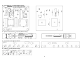
30
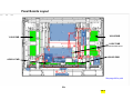
Panel Boards Layout
X-SUS PWB
Y-SUS PWB
LOGIC PWB
located behind Main Board
A-BUS-R PWB
A-BUS-L PWB
See page 44 for p/n's
30a
CH 2
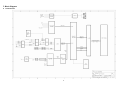
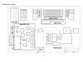
10. Basic Block Diagram
31
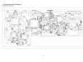
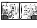
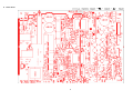
11. Printed Wiring Board Diagram
z
Main Board-Top Side
32
z
Main Board-Bottom Side
33
z
I/O Board-Top Side
z
RS-232 Board-Top Side
● Audio Board-Top Side
34
z
Audio Transfer Board-Top Side(L)/Bottom Side(R)
35
z
Power/EMI Board-Top Side(L)/Bottom Side(R)
z
Speaker Connector Board-Top Side(L)/Bottom Side(R)
z
Key Pad-Top Side(L)/Bottom Side(R)
z
IR Board-Top Side(L)/Bottom Side(R)
36
z
HDMI Board-Top Side(L)/Bottom Side(R)
37
z
Power Board
38
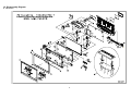
12. Disassembly Diagram
z
Mechanical
39
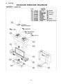
z
Packing
40
13. Replacement Parts List
z
Mechanical & Packing part list
NO. DESCRIPTION
PART NO.
M1
Front Cover Ass'y
5096454886
M2
Function Key
E642851202
M3
Rear Cover Ass'y
5096154886
M4
SPK Cover
E641105000
M5
Power Cap
E641100500
M6
Edge Saddle
E642678500
M7
Tape of al foil(25x580)
E648006524
M8
Tape of al foil(25x980)
E648006525
M9
Tape of al foil(50x20)
E648006506
M10 Sponge (570x7x2.5)
E642018222
M11 Sponge (985x6.5x5.5)
E642018223
M12 Cable Clamp
E640105200
M13 Panel Supporter Mylar
E646522200
M14 Washer
E646522300
M15 NON-WOVEN FABRICS
E642025810
M16 GASKET 585X10X1
E642025339
M17 GASKET 963X10X1
E642025309
M18 GASKET 624X5X1
E642025316
M19 GASKET 1025X5X1
E642025315
M20 GASKET
E642025349
M21 Special Screw
E640223000
M22 Wire Saddle
E640104007
M23 Wire Saddle
E642583500
M24 Wire Saddle
E642583501
M25 Washer
E640229301
M26 SPONGE
E642026417
M27 SPONGE-SPK
E642026418
M28 SPONGE-SPK
E642026419
M29 BASE ASS’Y
5095854857
M30 Tray
I514104256
M31 EPS Bottom (BR)
I524100256
M32 EPS Bottom (BL)
I534054356
M33 EPE Bag
M34 HS Carton
I514100756
M35 EPS Top (TR)
I524100156
M36 EPS Top (TL)
I534100356
M37 Grip Joint
41
M38 Clip PE Bag
I533251157
M39 EPS Bottom(BM)
I524100456
M40 EPE Bag
I534100256
42
z
Electrical part list
NO.
DESCRIPTION
PART NO.
ASSEMBLY PCB-MAIN BOARD (PWB-0891)
5097652009
ASSEMBLY PCB-I/O (PWB-0899)
5097651805
ASSEMBLY PCB-KEY PAD (PWB-0874)
5097659800
ASSEMBLY PCB-KEY IR (PWB-0874)
5097659801
ASSEMBLY PCB-RS-232 BOARD
(PWB-0832)
5097643008
ASSEMBLY PCB-POWER/EMI (PWB-0905)
5097651912
ASSEMBLY PCB-AUDIO (PWB-0807)
5097639914
ASSEMBLY PCB-AUDIO POWER
(PWB-0905)
5097651913
ASSEMBLY PCB-CONNECTOR (PWB-0833)
5097642804
ASSEMBLY PCB-SPEAKER CONNECTOR
(PWB-0906)
ASSEMBLY PCB-HDMI (PWB-0892)
5097653206
5097652105
P301
POWER CORD
E056701000
P302
D-SUB SIGNAL CABLE
E057315500
P303
S-VIDEO CABLE
E057304500
P304
AV CABLE
E057303500
RM01
REMOTE CONTROLLER
E052731079
Y001
USER’S MANUAL
E030039028
Y002
WARRANTY CARD
E030230010
Y003
QUICK SETUP GUIDE
E030039029
Y007
WARRANTY CARD (CANADA)
E030230012
GL01
SCREEN FILTER 42”
5771900152
H001
TUNER MODULE
5052110027
J001
QUICK TIE
5071000531
UA01
ATSC MODULE (w/QAM)
5053911108
UA02
POWER MODULE
6693006618
P201
WIRE ASSEMBLY W2/2P
E057402005
P203
WIRE ASSEMBLY W11/10P
E057411001
P204
WIRE ASSEMBLY W31/30P
E057431012
P205
WIRE ASSEMBLY W10/10P
E057410010
P206
WIRE ASSEMBLY W20/20P
E057420004
P207
FFC 50P+AI
E784650506
P208
WIRE ASSEMBLY W9/9P
E057409002
P209
WIRE ASSEMBLY W4/4P
E057404009
P211
WIRE ASSEMBLY W5/5P
E057405008
P212
WIRE ASSEMBLY W5/5P
E057405011
P215
WIRE ASSEMBLY
E057401009
P811
WIRE ASSEMBLY
E057401008
P813
WIRE ASSEMBLY W3/2P
E057403015
P814
WIRE ASSEMBLY W3/3P
E057403016
43
P9001A WIRE ASSEMBLY W8/8P
E057408006
P9003A WIRE ASSEMBLY W4/4P
E057404011
S811
POWER SWITCH PANASONIC
E054501008
SP01
SPEAKER BOX ASSEMBLY
E055100002
T811
EMI FILTER SOCKET TYPE DIT
E061133007
T811A HEATED SHRINK TUBE
g
h
i
j
k
l
E075500001
CABLE LOGIC-ABUSL
A3(FPF29R-CBL001401)
CABLE LOGIC-XSUS
A3(FPF29R-CBL001411)
CABLE LOGIC-YSUS
A3(FPF29R-CBL001412)
CABLE LOGIC-ABUSR
A3(FPF29R-CBL001421)
CABLE XSUS-YSUS
A3(FPF29R-CBL003601)
CABLE XSUS-ABUSR
A3(FPF29R-CBL003701)
5000100119
5000100120
5000100121
5000100122
5000100123
5000100124
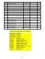
Part Numbers for Boards and Assemblies
FPF29R-ABL0030 ABUS-L PWB
FPF29R-ABR0031 ABUS-R PWB
FPF29R-LGC0057 LOGIC PWB
FPF29R-XSS0037 X-SUS PWB
FPF29R-YSS0038 Y-SUS PWB
FPF42C128128UE5 PDP Panel
5052110027
TUNER MODULE
5053911108
ATSC MODULE (w/QAM)
5097639914
ASSEMBLY PCB-AUDIO
5097642804
PWB ASS'Y CONNECTOR
5097643008
ASSEMBLY PCB-RS-232 BOARD
5097651805
ASSEMBLY PCB-I/O
5097651912
ASSEMBLY PCB-POWER/EMI
5097651913
ASSEMBLY PCB-AUDIO POWER
5097652009
ASSEMBLY PCB-MAIN BOARD
5097652105
ASSEMBLY PCB-HDMI
5097653206
ASSEMBLY PCB-SPEAKER CONNECTOR
5097659800
ASSEMBLY PCB-KEY PAD
5097659801
ASSEMBLY PCB-KEY IR
5771900152
SCREEN FILTER 42"
6693006618
POWER MODULE
44