1
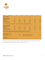
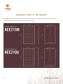
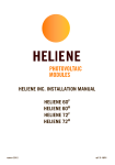
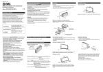
1
INDEX
INDEX................................................................................ 1
TECHNICAL CHARACTERISTICS............................................................ 2
FAMILY HEE 215 M .................................................................... 4
FAMILY HEE 210 U .................................................................... 6
ELECTRICAL VALUES ..................................................................... 8
AMPS/VOLTAGE CURVES VARIATION DUE TO SOLAR RADIANCE & TEMPERATURE ............................. 9
POTENTIAL POWER POWER CURVE ........................................................... 10
JUNCTION BOX........................................................................ 11
DIODE CHARACTERISTICS ................................................................. 12
WARNINGS AND ELECTRICAL RISKS....................................................... 13
CONNECTION LIMIT OF THE MODULES..................................................... 15
MODULE WIRINGS ...................................................................... 15
RECOMMENDATIONS FOR THE INSTALLATION................................................ 16
INSTALLATION REQUIREMENTS ............................................................. 18
GROUNDING .......................................................................... 19
MOUNTING INSTRUCTIONS............................................................... 20
FRENCH VERSION ...................................................................... 21
MAINTENANCE......................................................................... 22
DIAGNOSTICS AND TROUBLESHOOTING..................................................... 23
ANNOTATED VIEWS OF THE MODULES...................................................... 24
CERTIFICATES........................................................................ 25
1
Technical characteristics
Heliene solar modules belong to the latest generation of mono-crystalline and multi-crystalline 6in (156mm)
cells. Their contoured surface, and three current-collecting bars system, provide higher generating power and
homogeneous aesthetics.
Each module consists of 60 high-quality cells in serial configuration to achieve optimal power and voltage for
photovoltaic systems, either connected to the grid or not.
Before designing, assembling, operating, or proceeding with the maintenance of photovoltaic modules
HEE210U or HEE215M, please read carefully all of the instructions and recommendations in this manual.
Helios Energy Europe, S.L. Heliene Inc. and Helios USA LLC disclaim any liability for breakage, deterioration or
the loss of performance of any of our modules resulting from the incorrect INSTALLATION, use, and/or
maintenance.
The junction box has a level of protection of IP65 against infiltration of dust and water, AND houses the
connection of the metallic output bands of the module to the cables (positive and negative). The bypass diodes
are connected INSIDE, ENSURING THE thermal stability of the cells in case of shading DURING the hours of
irradiation.
Two isolated copper cables, 4mm2 (see annex A for AWG mm2 sizing) and 1.2 m long emerge from the junction
box. Each cable is connected at its end with multi-contact plugs, one male, and one female, which facilitate the
connection of the modules by forming serial connections to reach the adequate voltage for the system.
In order to protect the module against back-feed, fast acting fuses of 10 A should BE used in series connection.
2
HEE-EN-UL-REV 2.0 AUG -31
PHOTOVOLTAIC CELL
ALUMINIUM FRAME
TEMPERED GLASS
ENCAPSULANT
CELLS CONNECTION
TABS
BACKSHEET
Tedlar-TPT Sheet
BY-PASS DIODE
JUNCTION BOX
WATER EVACUATION
GROUNDING TERMINAL
Figure 1. Cross-section of a module identifying different components.
HEE-EN-UL-REV 2.0 AUG-31
3
Family HEE 215 M
The maximum power value, open circuit voltage and short circuit current of any individual module will be ±3%
of these values. Specifications are subject to change.
4
HEE-EN-UL-REV 2.0 AUG -31
Les tolérances acceptées entre chaque module et la valeur de référence sont de ±3% pour les données de
puissance maximale, tension de circuit ouvert et courant de court circuit.
HEE-EN-UL-REV 2.0 AUG-31
5
Family HEE 210 U
The maximum power value, open circuit voltage and short circuit current of any individual module will be ±3%
of these values. Specifications are subject to change.
6
HEE-EN-UL-REV 2.0 AUG -31
Les tolérances acceptées entre chaque module et la valeur de référence sont de ±3% pour les données de
puissance maximale, tension de circuit ouvert et courant de court circuit.
HEE-EN-UL-REV 2.0 AUG-31
7
Electrical values
In actual conditions, the variation of the parameters of operation for the cells will be related to the variation of
irradiation received and the actual temperature. These parameters show the indicated values in the previous
charts.
The variations of the working point of the model according to the modification of different operation
parameters are shown in the next page.
8
HEE-EN-UL-REV 2.0 AUG -31
Amps/Voltage Curves Variation due to Solar Radiance & Temperature
Figure 2. Variation of the work curve Amps-Voltage according to the incidental
solar radiance to a cell temperature of 25 ºC
Figure 3. Variation of the work curve Amps-Voltage according to the temperature
of the cell
HEE-EN-UL-REV 2.0 AUG-31
9
Potential Power Curve
Figure 4. Curve of the potential produced by a photovoltaic module in reference
to the working point.
In the above figure, it can be observed that there is a point for which the product IxV reaches its maximum.
This point, called the maximum power point, determines the expressed peak power using the units (Wp).
The ability of the system to trace this point in relation to the variation of working conditions of the module , is
called, "tracing of the point of maximum potential (MPPT)".
10
HEE-EN-UL-REV 2.0 AUG -31
Junction Box
The junction box can be found on the backside of the module. Inside of it, all the connections are made from
the series soldered cells to the terminals, linking through by-pass diodes, and through circuit board to +/outputs to the cables which have (multi type) connectors on ends.
The junction box does not require any extra field wiring at the terminals.
Changing wires or modifying any piece of the junction box will void the module warranty.
Figure 5. Electrical outline of the connection between the cells and the
diodes, that interacts in the photovoltaic solar module.
Any shadowing of cells resulting from the projection of any object or from the accumulation of dirt or debris
can result in reverse voltage. The junction box contains three by-pass diodes to avoid this problem.
The reverse polarization of a cell can lead to consuming the energy produced by the rest of the system. The
dissipation of this energy can lead to dangerous overheating and affect the cell. Damage can include, but not
being limited to, the release of its anti-reflection cap, the perforation of the P-N union or even the breakage of
the soldering.
By-pass diodes have the capacity to run a current larger than the maximum produced by the module and block
the reverse current generated by the system itself to avoid over-heating.
HEE-EN-UL-REV 2.0 AUG-31
11
Diode characteristics
Both families of modules, HEE215M and HEE21OU, contain three by-pass diodes each, with the following
characteristics:
Model Type
ULTRAFAST RECTIFIERS
Maximum Average Forward Current
@Tc = 150°C: 15 A
Maximum DC Blocking Voltage
Maximum Instantaneous Reverse Current
200 V
@Tc = 25 ºC: 10 µA
@Tc = 150 ºC: 500 µA
Breakdown Reverse Current
12
12 A
HEE-EN-UL-REV 2.0 AUG -31
WARNINGS AND ELECTRICAL RISKS
• Each Module produces a continuous current (DC) when it is exposed to sunlight or other light sources.
Contact with any of the electrically active parts of the module, such as terminals, can result in injury or death,
regardless whether the module is connected or not.
• The modules must be handled and installed only by certified electricians.
• The modules are packed and protected to avoid transportation and handling damage. This packaging must
not be removed until the moment of installation to avoid damage.
• The modules should be stored in a dry and temperature controlled place prior to their installation, always in
a well-balanced position. Please note that dropping can result in glass breakage. A module with a broken glass
must not be installed. Broken glass can produce fragments that may cause injury to personnel handling it.
• The module’s glass is tempered and therefore has higher resistance to impact. However, impact of a tool can
cause serious damage to it. Modules should be handled with extreme caution to avoid impact from any tool or
other heavy objects. Walking on the modules should also be avoided. (Maximum load rating is 146.5 Kg/m2)
• Do not disassemble the module or remove any of its parts. Improper handling of the junction box may
produce loss of the waterproof rating and electrical protection, which may lead to deterioration and/or
corrosion of the unit. Do not handle the bypass diodes or their connections either.
• The module already contains all the necessary wiring for its connection, so the junction box must not be
interfered with in its installation.
• The photovoltaic solar module has been designed to work with levels of incidental irradiance normally found
on the Earth´s surface. Do not concentrate the radiation without the express consent of authorized personnel
as this concentration without rigorous and uniform control can produce malfunctions and can affect some cells
of the module.
• The photovoltaic module produces a voltage in the form of current that always continues as long as the unit is
illuminated. As a precaution, it is recommended that the module should be covered for its handling and/or
connection or otherwise the connection should be done in hours of low intensity of irradiance.
HEE-EN-UL-REV 2.0 AUG-31
13
• The tools used to connect the modules must comply with provincial electrical safety regulations. hey must be
dry and have the correct level of insulation.
• The connection and disconnection of the photovoltaic modules can produce sparks. Do not attempt to
connect or disconnect the modules in the presence of flammable substances.
• Each module string must have adequate protection against excesses of current using fast acting fuses and
against excesses of voltage using variable resistors.
• Under normal conditions, a photovoltaic module is likely to experience conditions that produce more current
and/or voltage than reported at standard test conditions. Accordingly, the values of ISC and VOC marked on
this module should be multiplied by a factor of 1.25 when determining component voltage ratings, conductor
capacities, fuse sizes, and size of controls connected to the PV output. Please refer to the provincial electrical
safety code for additional information.
14
HEE-EN-UL-REV 2.0 AUG -31
CONNECTION LIMIT OF THE MODULES
The thickness and composition of their back sheets provide Heliene’s modules with electrical insulation of i600
Vcc, according to the UL regulation. As a result, they can be connected to each other in groups of up to 16.
Despite the previous statement, the current limit of the connection of the modules is defined by the voltage that
can enter to the inverters, which tends to be around 500 Vcc. This value would limit the number of modules
that can be connected in series to 13 (calculated to an external temperature of -10ºC).
However, there is no limit as to the connection of modules in parallel, as the operation of one does not affect
the others, except for the limitation that they must all work at the same voltage level. Therefore, all the
modules connected in parallel must have an equal number of cells, in this way avoiding the recirculation of
current between rows of modules.
In case of a parallel connection, the new maximum intensity allowable to the inverter is the limit of the number
of modules to be installed.
Module wirings
• The wiring must ensure that the loss of nominal potential is less than 2 %; it is recommended to maintain that
loss around 1 % of the nominal power.
• The recommended rating for wiring connections is 6mm2 and never less than 4mm2 , (10 AWG recommended
and never less than 12 AWG). Use only cable listed by UL 4703 PV Wire, 90ºC thermal insulated in accordance
with local fire, building and electrical code.
HEE-EN-UL-REV 2.0 AUG-31
15
RECOMMENDATIONS FOR THE INSTALLATION
The modules must be secured to structures that support them using anchors that take into account the
constraints imposed by the resulting movements of the processes of thermal expansion and contraction.
To achieve the maximum annual yield, the installer shall determine the optimum orientation and tilt of the PV
modules. Generation of maximum power occurs when sunlight shines perpendicularly onto the front surface
PV modules.
Avoid shading
Even the slightest partial shading (e.g., from dirt deposits) will cause a reduction in yield. A module is
considered "shadow-free" if it is unobstructed across its entire surface regardless the time of the year. Even on
the shortest day of the year, unobstructed sunlight should reach the module front surface.
Reliable ventilation
Sufficient clearance between the module frame and the mounting surface is required to allow cooling air to
circulate around the back of the module. The clearance should also allow any resulting condensation or
moisture to dissipate.
The solar module should be assembled in the best possible orientation (South) and kept free from shadows,
including partial shadows, to be able to obtain a good performance. Calculate the best inclination of the system
depending on the latitude; to achieve a good self-cleaning effect through precipitation, the tilt of the modules
should be at least 20°.
• Each module should be situated with at least 15 centimetres of open space behind it to ensure that the
ventilation dissipates the heat produced by the cells, and that the losses from this effect are minimal.
• If the modules are installed one beside the other, the height of the hardware should be levelled to avoid the
projection of shadows.
• The anchors that connect the module frame to the structure and the structure to the building must comply
with the standards for wind resistance outlined by the local building code.
16
HEE-EN-UL-REV 2.0 AUG -31
• Prior to the installation of modules, contact the appropriate authorities to determine installation permits and
inspections.
• Check applicable building codes to ensure that the construction or structure (roof, facade, support, etc.)
where the modules are being installed has appropriate strength.
• When installing the modules, please ensure the assembly is mounted over a fire resistant roof covering rated
for the application and required a slope less than 5in/ft (127 mm/305 mm) to maintain a fire class rating.
• The modules must not be installed in the proximity of highly flammable substances (e.g., filling stations, gas
containers, paint equipment) since the connection and disconnection process may produce sparks.
• The modules must not be installed near open flames or flammable materials.
• Do not expose modules to artificially concentrated light sources.
• The modules must not be immersed or continuously exposed to water
• There is a risk of corrosion when modules are exposed to salt (i.e., marine environments) or sulphur (i.e.,
sulphur sources, volcanoes).
HEE-EN-UL-REV 2.0 AUG-31
17
Installation Requirements
• Ensure that the modules meet technical requirements of the PV system as designed.
• Ensure that other system components do not exert damaging mechanical or electrical influence on the
modules.
• Modules can be wired in series to increase voltage or in parallel to increase current. To connect in series,
connect cables from the positive terminal of one module to the negative terminal of the following one. To
connect in parallel, connect cables from the positive terminal of one module to the positive terminal on the
following.
• Connect the quantity of modules that match the voltage specifications of the inverters used in the system.
The modules must not be connected together to create a voltage higher than the permitted system voltage.
• In order to avoid (or minimize) mismatch effects in arrays, it is recommended that identical electrical
performance of modules should be connected within the same series.
• Modules should be firmly fixed in place in a manner suitable to withstand all expected loads, including wind
and snow loads.
• The small openings on the underside of the modules allow rain to run out. Make sure that these openings are
not obstructed after mounting.
18
HEE-EN-UL-REV 2.0 AUG -31
Grounding
The modules are certified double insulated, however it is recommended that they be grounded. In U.S. and
Canada only: all PV modules must be grounded by electrical connection from the module frames to the ground.
A UL-listed grounding lug should be used.
Ensure compliance with all local electrical codes and regulations.
Several different methods of grounding can be used to provide the required connection through the anodized
frame; the following methods of performing this task are acceptable.
A UL-listed grounding lug may be used. The existing grounding holes in the module frames should be used as
the point of attachment to the module frame (the diameter M8 –5/16”- groundings holes on the module frame,
identified with a yellow label). To ensure a conductive connection, i.e. to penetrate the non-conductive coating
on the frame, a combination of screw, spring washer and lock nut must be used to mount the grounding lug
onto the frame. The spring washer must be placed between the frame and the grounding lug. Use all stainless
steel hardware to mount the lug to the module frame.
The grounding lug has to be capable of accepting a 4-14 AWG (see annex
A for AWG mm2 sizing) copper conductor. Modules can be grounded using
clip systems provided they have been tested and certified to local
regulation on anodized aluminium frame and are installed according to
the manufacture’s specified instructions.
Connect module frames to each other using cables with cable lugs. All the
connections on the conductive connection must be fixed. Metal
containing iron in the conductive connection should be treated against
corrosion by anodization, spray-painting, or galvanization to prevent
rusting and corrosion. Another method is to ground the frame of the
module to racking structure in accordance with NEC requirements for
grounding solar electrical systems.
HEE-EN-UL-REV 2.0 AUG-31
19
MOUNTING INSTRUCTIONS
Modules should be bolted to support structures through mounting holes located in the frame's back flanges
only; Do not drill additional holes, doing so will void the warranty. Each module must be securely fastened at a
minimum of 4 points.
Assure to comply with all local building codes.
HELIENE modules could be mounted on a roof: freestanding modules turn a class B rooftop into a class C
rooftop.
Use appropriate corrosion-proof fastening materials.
Top or bottom clamping methods will vary and are dependent on the mounting structures. Follow mounting
guidelines recommended by the PV RACKING supplier.
The mounting design must be certified by a registered professional engineer. The mounting design and
procedures shall comply with local codes and all authorities having jurisdiction.
Use a torque wrench for installation (torque to amount specified by professional engineer). The figure BELOW
shows methods of fastening a module to a support structure.
Bolting
20
Clamping on
HEE-EN-UL-REV 2.0 AUG -31
French version
Les tolérances acceptées entre chaque module et la valeur de référence sont de +-3% pour les données de
puissance maximale, tension de circuit ouvert et courant de court circuit.
Si l'on souhaite fixer le module à une structure support nécessitant un perçage du cadre, il est nécessaire de le
faire au niveau des trous prévus à cet effet. Il ne faut pas réaliser de nouveaux perçages dans le cadre du
module sous peine de se voir retirer la garantie sur le module.
Il est nécessaire de s'assure que l'ensemble des règles locales de construction ont été respectées lors de la mise
en oeuvre du matériel.
Les modules Heliene peuvent être montés en toiture. La présence de modules solaires en montage surimposé
fait la passer un toit de classe B à un toit de classe C.
Il est nécessaire d'utiliser des matériaux et équipements de montage et serrage ayant les propriétés d'anticorrosion adéquates.
Le mode de fixation haut et bas des modules varie en fonction de la structure de montage utilisée. Il est
nécessaire de suivre les instructions de pose du fabricant de structure de montage solaire PV.
Le design du montage doit être certifié par un ingénieur professionnel enregistré. Les procédures et design du
montage doivent être en accord avec les règles et normes locales ainsi qu'avec l'ensemble des autorités et
administrations compétentes.
Utiliser pendant le montage des outils présentant des mesures de couple. Les figures précédentes montrent
différentes méthodes de fixation des modules à la structure.
HEE-EN-UL-REV 2.0 AUG-31
21
MAINTENANCE
• Cleaning of the modules improves the optical performance. The cleaning should always be done using clean
water with low calcium concentration and without detergents or abrasives. The water should not be applied at
high pressure and scrapers or other cleaning tools should not be used as they may cause scratches on the glass.
Avoid producing a thermal shock using cold water when glass could be at a very high temperature (e.g. at
noon).
• Visual inspection of the module. A thorough visual inspection of the modules should be conducted once or
twice a year, noting possible effects of aging or corrosion. In this inspection, special attention should be given
to the integrity of the glass, the aluminium frame, the silicone seals, the waterproof of the junction box,
oxidation of the contacts between cells and condensation in the interior of the laminate. These tasks should be
done at least once a year by qualified personnel.
• Testing of the wiring and the connections. At least once a year, the integrity and waterproof of all of the parts
that make up the wiring and connections of the solar installation should be tested: junction boxes, isolation of
outdoor cables, protective tubing, connection links of connectors, support cables, fuse boxes, etc. This work,
along with the measuring of isolation distances and resistance of the installation to the ground should be done
by qualified personnel duly trained and equipped for the job.
22
HEE-EN-UL-REV 2.0 AUG -31
DIAGNOSTICS AND TROUBLESHOOTING
The strict quality controls in the factory ensure that HELIENE modules are sold free of defects, breakages
and/or others problems. However, in its operation some problems may arise that can alter the correct
operation of the modules. They are detailed as follows:
Breaking of the glass. The tempered glass that is part of the modules is resistant to impact however poor
handling during transport or installation as well as excessive mechanical tension in the racking structure, or
impact can break the glass. Chipping of the surface might reduce the transparency of the module.
Accumulation of dirt and humidity between the spots might lead to freezing, increasing the separation of the
frames. Regardless, the module will continue producing power between 50 and 70 % of its capability.
Loss of seal of the junction box.
Short-circuit of the module: An excess of intensity due to meteorological phenomena or mistakes in the
connection can cause damage, short-circuiting some of the bypass diodes contained in the module. As a result,
the voltage of the module will decline in proportion to the damaged diodes to 2/3, 1/3, or 0 V. In this case, the
bypass diodes must be substituted only by HELIENE personnel.
HELIENE guarantees its modules for ten years. In the event of accelerated deterioration of the module, Heliene
should be notified immediately to make the necessary replacement.
HEE-EN-UL-REV 2.0 AUG-31
23
ANNOTATED VIEWS OF THE MODULES
HELIENE modules of the HEE 215 M and HEE 210 U families are assembled with the same type glass and
aluminium frame. They share, therefore, the same dimensions:
24
HEE-EN-UL-REV 2.0 AUG -31
CERTIFICATES
Technical File with Certification of the CE trademark, tests in Leitat Technical Center and AT4 Wireless with
certification ENAC, in accordance with the IEC.
Certificates:
•
Certificate Heliene CE
•
Certificate of Heliene Guarantee
•
Factory Certificate TÜV
•
Integrated Modules Certificate TÜV
•
Monocrystalline Modules Certificate TÜV
•
Multicrystalline Modules Certificate TÜV
•
Test Certificate AT4 - HEE215M, IEC 61215 y IEC 61730, UL 1703
•
Test Certificate AT4 - HEE210U, IEC 61215 y IEC 61730, UL 1703
•
Certificate ULC/ORD-C1703-01
•
CETLUS
•
CEC listed
mark with listed number 4001272
HEE-EN-UL-REV 2.0 AUG-31
25
26
HEE-EN-UL-REV 2.0 AUG -31