1
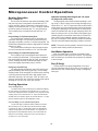
Installation Information
Water Piping Connections
Synergy3D Installation Manual
Geothermal Heat Pumps with Water Heating for Radiant Floor Applications
• 3 thru 6 Ton
Electrical Connections
Startup Procedures
IM1602 04/08
WaterFurnace
Preventive Maintenance
SYNERGY3D INSTALLATION MANUAL
Table of Contents
Model Nomenclature
2
General Installation Information
3-5
Closed Loop Systems
6
Open Loop Systems
7
Buffer Tank Installation
8
Electrical
9
Thermostat Installation
10
Physical Data
11
Dimensional Data
12
Microprocessor Control Operation
13-15
Operating Limits
16
Correction Factors
17
Auxiliary Heat
18
Blower Performance & Auxilary Heat Data
19
Startup Checklist
20
Startup/Troubleshooting Form
21-23
1
SYNERGY3D INSTALLATION MANUAL
Model Nomenclature
S
D
V
049
A
1
1
1
N
T
Model Type
S= Synergy3D Dual Capacity
L
Return Air Configuration
L= Left
R= Right
Compressor Type
D= Daul Capacity
Discharge Air Configuration
T= Top
Cabinet Configuration
V= Vertical
Coax Options
C= Copper
N= Cupronickel
Unit Capacity
Fan Option
1= ECM
2= Oversized ECM Blower Option
(038 & 049)
Vintage
A= Vintage
Voltage
1= 208/230/60/1
Hot Water Option
0= None
1= Hot Water Generation with
factory installed pump
2
SYNERGY3D INSTALLATION MANUAL
General Installation Information
Safety Considerations
Installation and servicing of heating and air conditioning equipment can be hazardous due to system pressure and electrical components. Only trained and qualified service personnel should install, repair or service heating and air conditioning
equipment.
Untrained personnel can perform basic maintenance functions of cleaning coils and cleaning and replacing filters. All
other operations should be performed by trained service personnel. When working on air conditioning equipment, observe
precautions in the literature, tags and labels attached to the unit and other safety precautions that may apply.
Follow all safety codes. Wear safety glasses and work gloves. Use quenching cloth for brazing operations. Have fire
extinguisher available for all brazing operations.
WARNING: Before performing service or maintenance operations on the system, turn off main power switches to the unit.
Turn off accessory heater power switch if applicable. Electrical shock could cause serious personal injury.
Moving and Storage
Move units in the normal “Up” orientation. Vertical units are not to be moved, but may be stored one upon another to
a maximum height of two units. When the equipment is received, all items should be carefully checked against the bill of
lading to be sure all crates and cartons have been received. Examine units for shipping damage, removing the units from
the packaging if necessary. Units in question should also be internally inspected. If any damage is noted, the carrier should
make the proper notation on the delivery receipt, acknowledging the damage.
Unit Location
Locate the unit in an indoor area that allows easy removal of the filter and access panels, and has enough space for service personnel to perform maintenance or repair. Provide sufficient room to make water, electrical and duct connection(s). If
the unit is located in a confined space, such as a closet, provisions must be made for return air to freely enter the space by
means of a louvered door, etc. Care should be taken when units are located in unconditioned spaces to prevent damage
from frozen water lines and excessive heat that could damage electrical components.
CAUTION: A minimum of 24-inch clearance should be allowed for access to front access panel.
Setting Vertical Units
Vertical units are available in left or right hand return configuration. Vertical
units should be mounted level on a vibration absorbing pad slightly larger than
the base to provide isolation between the unit and the floor. It is not necessary to
anchor the unit to the floor (See Figure 1).
Duct System
Figure 1: Vertical Unit Mounting
Vibration
Absorbing
Mesh
An air outlet collar is provided on vertical top flow units to facilitate a duct
Air Pad
connection, which is shipped inside the unit. A flexible connector is recommended
for discharge and return air duct connections on metal duct systems. Uninsulated
duct should be insulated with a minimum of 1-inch duct insulation. Application of
the unit to uninsulated ductwork in an unconditioned space is not recommended
as the unit’s performance will be adversely affected.
If the unit is connected to existing ductwork, a previous check should have been made to assure that the duct has the
capacity to handle the air required for the unit application. If ducting is too small, as in the replacement of heating only systems, larger ductwork should be installed. All existing ductwork should be checked for leaks and repaired when necessary.
The duct system should be sized to handle the design airflow quietly. To maximize sound attenuation of the unit blower,
the supply and return plenums should include internal duct liner of glass fiber or be of ductboard construction for the first few
feet. If air noise or excessive airflow is a problem, the blower speed can be changed. See the Blower Performance and Fan
Speed sections on page 16.
3
SYNERGY3D INSTALLATION MANUAL
General Installation Information (cont.)
Water Piping Connections
Figure 2: Female Locking Ring
All Synergy3D source water connections are swivel piping fittings that accept
a 1-inch Male Pipe Thread (MPT) (see Figure 2). The swivel pipe connector has a
rubber gasket seal similar to a garden hose gasket, which when mated to the flush
end of 1-inch threaded pipe provides a leak-free seal without the need for thread
sealing tape or compound. Check to ensure that the rubber seal is in the swivel
connector prior to attempting any connection. The rubber seals are shipped attached to the air coil inside the blower compartment.
To make the connection to a ground loop system, mate the brass connector
(supplied in CK4L and CK4L-GL connector kits) against the rubber gasket in the
swivel connector, and thread the female locking ring onto the pipe threads, while
maintaining the brass connector in the desired direction (see Figure 2). Tighten the
connectors by hand and then gently snug the fitting with pliers to provide a leak
proof joint. When connecting to an open loop (ground water) system, thread 1inch MPT fitting into the swivel connector and tighten in the same manner as noted
above. The open and closed loop piping system must include pressure/temperature taps for serviceability.
Never use flexible hoses smaller than 1-inch inside diameter on the unit and
limit hose length to 10 feet. per connection. Check carefully for water leaks.
CAUTION: Water piping exposed to outside temperature may be
subject to freezing.
Water Quality
Stainless
Steel
Snap Ring
Gasket
Material
Locking
Ring
Gasket
Support
Sleeve
Note: Load side fittings are
same type as source.
In ground water situations where scaling could be heavy or where biological growth such as iron bacteria will be present, a closed loop system is recommended. The heat exchanger coils in ground water systems may, over a period of time,
lose heat exchange capabilities due to a buildup of mineral deposits inside. These can be cleaned, but only by a qualified
service mechanic, as special solutions and pumping equipment are required. Desuperheater coils can likewise become
4
SYNERGY3D INSTALLATION MANUAL
General Installation Information (cont.)
scaled and possibly plugged. In areas with extremely hard water, the owner should be informed that the heat exchanger
may require occasional flushing.
Units with cupronickel heat exchangers are recommended for open loop applications due to the increased resistance to
build-up and corrosion, along with reduced wear caused by acid cleaning.
Freeze Sensing
Set the freeze sensing switch SW2 #2 to “Loop” on the printed circuit board for applications using a closed loop antifreeze solution. On applications using an open loop/ground water system, set to “Well” (the factory setting). If using closed
loop and no antifreeze solution leave in “Well” position (the factory setting).
Condensate Drain
The internal condensate drain assembly consists of a drain tube, which is attached to the drain pan, a 3/4-inch PVC female adapter, and a flexible connecting hose. The female adapter may exit either the front or the side of the vertical cabinet.
The adapter will be glued to the field-installed PVC condensate piping. A condensate hose is inside all cabinets as a trapping loop; therefore, an external trap is not necessary.
Air Coil
To obtain maximum performance the air coil should be cleaned before start up. A 10% solution of dishwasher detergent
and water is recommended for both sides of coil; a thorough water rinse should follow.
5
SYNERGY3D INSTALLATION MANUAL
Closed Loop Ground Source Systems
Once piping is completed between the unit, flow center and the ground loop (Figure 3), final purging and charging of the
loop is needed. A flush cart (at least a 1.5 HP pump) is needed to achieve adequate flow velocity in the loop to purge air and
dirt particles from the loop itself. Antifreeze solution is used in most areas to prevent freezing. Flush the system adequately
to remove as much air as possible then pressurize the loop to a static pressure of 50-75 psi (winter) or 40-50 psi (summer).
This is normally adequate for good system operation. Loop static pressure will fluctuate with the seasons. Pressures will
be higher in the winter months than during the cooling season. This fluctuation is normal and should be considered when
charging the system initially.
After pressurization, be sure to remove the plug in the end of the loop pump motor(s) (if Grundfos® pumps are used) to
allow trapped air to be discharged and to ensure the motor housing has been flooded. Ensure the loop flow center provides
adequate flow through the unit by checking pressure drop across the heat exchanger and comparing it to the figures shown
in unit capacity tables in Specification Catalog SP1554. Usually 2.5-3 gpm of flow per ton of cooling capacity is recommended in earth loop applications. See wiring schematics on pages 10 and 11 for loop pump power wiring details.
Figure 3 - Closed Loop: Ground Source Application
Unit Supply
Auxiliary
Heat Supply
GeoLink
Polyethylene w/
Armaflex
Flexible
Duct
Collar
TO
LOOP
GeoLink
Flow
LPK
Center*
Auxiliary
Heater
Knockout
External
Pump
Power
Disconnects
(If Applicable)
Drain
* For complete
GeoLink Flow
Center installation
information refer
to IM1961
Connector Kits with Armaflex
Low
Voltage to
Thermostat
P/T Plugs
Unit Power
Vibration Absorbing Pad
Multiple Units on One Flow Center
When two Synergy3D units or one Envision unit and one Synergy3D unit are connected to one loop pumping system,
pump control is automatically achieved by connecting the slave terminals on connector P2 in both units with 2-wire thermostat wire. These terminals are polarity conscious (see Figure 5). The loop pump(s) may be powered from either unit, whichever is more convenient. If either unit calls, the loop pump(s) will automatically start.
6
SYNERGY3D INSTALLATION MANUAL
Open Loop Ground Water Systems
Typical open loop piping is shown in Figure 5. Always maintain water pressure in the heat exchanger by placing water contraol valves at the outlet of hte unit to prevent mineral precipitation. Use a closed, bladder-type expansion tank to
minimize mineral formation due to air exposure. Ensure proper water flow through the unit by checking pressure drip across
the heat exchanger and comparing it to the figures in the pressure drop tables. Normally about 2 GPM flow rate per ton of
cooling capacity (1.5 GPM per ton minimum at 50° F) is needed in open loop systems.
Discharge water from the unit is not contaminated in any manner and can be disposed of in various ways such as recharge
well, storm sewer, drain field, adjacent stream or pond, etc.depending on local building codes. Most local codes forbid the use
of sanitary sewer for disposal. Consult your local building and zoning department to ensure compliance in your area.
Figure 5 - Open System: Ground Water Application
Aux. Heat
Supply
Unit
Supply
Flexible Duct
Collar
Rubber Bladder
Expansion Tank
Auxiliary
Heater
Knockout
Flow
Regulator
Disconnects
(If Applicable)
Solenoid
Valve
Water
Out
Drain
Water In
Shut Off Valves
Unit
Power
Low Voltage
to Thermostat
and Valve
Shut-Off Valve
(to isolate solenoid
valve while acid flushing)
Strainer
P/T Plugs
Boiler Drains
For HX Flushing
Vibration
Absorbing Pad
Notes: For open loop ground water systems or systems that do not contain and antifreeze solution, set SW2-#2
to the “Well” position.
Figure 6: Open Loop Solenoid Valve Connection Option
Figure 7: BPV or PPV Valve Wiring
Typical slow operating external 24V
water solenoid valve (type VM) wiring.
Typical external 24V water
solenoid valves
(type PPV100,
BPV100) wiring.
Violet(2)
CC
VM valve
CC
Comfort
Alert
Blk(1)
CC
CC-GND
Comfort
Alert
Y1
Wht(4)
CC
Blk(1)
CC-GND
SS
Violet(3)
Y2
Violet(2)
CCHI
Logic Board
7
Violet(3)
Y1
Y2
Wht(4)
CCHI
Logic Board
SYNERGY3D INSTALLATION MANUAL
Desuperheater Connections
To maximize the benefits of the desuperheater a minimum 50-gallon water heater is recommended. For higher
demand applications, use an 80-gallon water heater or two 50-gallon water heaters connected in a series as shown
below. Electric water heaters are recommended. Make sure all local electrical and plumbing codes are met for installing
a desuperheater. The Synergy3D is not supplied with an internal circulator. A DPK5 kit will need to be purchased to
connect to the desuperheater. The DPK5 kit is supplied with installation instructions.
Typical Buffer Tank Installation
Figure 8: Synergy3D with Buffer Tank
6=B
1=:2
!"Þ2][SabWQ
!"Þ2][SabWQ
Þ1]\\SQbW]\a
Þ
4>B
EObS`4c`\OQS
3<D7A7=<
8
SYNERGY3D INSTALLATION MANUAL
Electrical
General
Be sure the available power is the same voltage and phase as that shown on the unit serial plate. Line and low voltage
wiring must be done in accordance with local codes or the National Electric Code, whichever is applicable.
Figure 9: Synergy3D Line Voltage 208-230/60/1
Unit Power Connection
Line Voltage connection is made by connecting the incoming line voltage wires to the “L” side of the contactor as shown in Figure 9. Consult the
Unit Electrical Data table below for correct fuse size.
External Loop Pump Power Connection
If the unit is to be used with an external loop pump (FC1 or FC2 flow
center), the pump(s) will be connected to the terminals on PB1 in the unit
electrical box as shown in Figure 4. The pumps will automatically be cycled
as required by the unit or by a secondary signal from another Synergy3D
unit sharing the flow center. (Refer to the wiring schematic on page 10-11.)
L2
L1
208 Volt Operation
All 208-230 volt units are factory wired for 230 volt operation. For 2098
volt operation, the red and the blue transformer wires must be switched on
terminal strip PS1. (Refer to wiring schematic on pages 10-11 for details.)
Figure 10: Wiring Multiple Units to One Flow Center
Synergy3D Unit #1
Shut
Down
C
C
SL1
In
With pump
wired to
Unit 1
Shut
Down
C
C
SL1
In
R
Y
O
G
L
S
C
VX, VL
SL1 not not
Out used used
Coil
With pump
wired to
Unit 2
24v
Normally Open
Contacts
SL1 not not
Out used used
Shut
Down
Envision or Synergy3D Unit #2
C
SL1
In
C
SL1 not not
Out used used
Synergy3D Unit #1
Electrical Data
Model
Rated
Voltage
Voltage
Min/Max
SDV038
SDV038*
SDV049
SDV049*
SDV064
SDV072
208-230/60/1
208-230/60/1
208-230/60/1
208-230/60/1
208-230/60/1
208-230/60/1
197/254
197/254
197/254
197/254
197/254
197/254
MCC
RLA
LRA
Int
Pump
FLA
26.0
26.0
33.0
33.0
40.0
42.5
16.6
16.6
21.1
21.1
25.6
27.2
82.0
82.0
96.0
96.0
118.0
150.0
1.75
1.75
1.75
1.75
1.75
1.75
Compressor
* With optional 1 HP ECM2 motor
Ext
Loop
FLA
Fan
Motor
FLA
Total
Unit
FLA
Min
Circ
Amp
Max
Fuse
calc
Max
Fuse/
HACR
5.4
5.4
5.4
5.4
5.4
5.4
4.0
7.0
4.0
7.0
7.0
7.0
27.8
30.8
32.3
35.3
39.8
41.4
31.9
34.9
37.5
40.5
46.2
48.2
48.5
51.5
58.6
61.6
71.8
75.4
45
50
50
60
70
70
3/18/08
Rated Voltage of 208-230/60/1.
Min/Max Voltage of 197/254.
HACR circuit breaker in USA only.
All fuses Class RK-5.
Local electrical codes overule any wiring recommendations.
9
SYNERGY3D INSTALLATION MANUAL
Thermostat Installation
Installation
Position the thermostat subbase against the wall so that it is level and the thermostat wires protrude through the subbase. Mark the position of the subbase mounting holes and drill holes with a 3/16-inch bit. Install anchors and secure base
to the wall. Thermostat wire must be 8 conductor 18 AWG wire. Strip the wires back 1/4-inch (longer strip lengths may cause
shorts) and insert the thermostat wires into the Synergy3D connector as shown in Figure 11. Tighten the screws to ensure
good connections. The thermostat has the same type of connectors, requiring the same wiring. See instructions enclosed in
the thermostat for detailed installation and operation information.
Figure 11 - Thermostat Wiring
24VAC
C
24VAC
(Common)
Y1
Compressor
W
Aux. Heat
O
Reversing
Valve
G
Blower
Relay
L1
System
Monitor
(Hot)
Thermostat Connection
Synergy3D Microprocessor
Controller
R
Other Thermostats
The Synergy3D unit is compatible with virtually any 24VAC thermostat. However, the multi-stage nature of this product
requires a 3-stage heating/2-stage cooling type thermostat.
Note: DIP switch SW2-8 is required to be in the “OFF” position for the control to operate with FaultFlash or
ComforTalk thermostats. SW2-8 in the “ON” position configures the control to operate with typical thermostats
(continuous lockout signal). There must be a wire connecting Y2 on the microprocessor controller to 2nd stage
compressor on the thermostat for proper operation.
10
SYNERGY3D INSTALLATION MANUAL
Physical Data
Model
038
049
Compressor (1 each)
Factory Charge R410a, oz [kg]
064
072
Copeland Scroll
90 [2.55]
95 [2.69]
124 [3.51]
128 [3.62]
ECM Fan Motor & Blower
Fan Motor Type/Speeds
Fan Motor- hp [W]
Blower Wheel Size (Dia x W), in. [mm]
ECM Variable Speed
1/2
[373]
11 x 10
[279 x 254]
1/2
[373]
11 x 10
[279 x 254]
1 [746]
1 [746]
11 x 10
[279 x 254]
11 x 10
[279 x 254]
Coax and Water Piping
Loop Water Connections Size - Swivel - in [mm]
1" [25.4]
1" [25.4]
1" [25.4]
1" [25.4]
Hydronic Water Connections Size - Swivel - in [mm]
1" [25.4]
1" [25.4]
1" [25.4]
1" [25.4]
HWG Connection Size - Swivel - in [mm]
1" [25.4]
1" [25.4]
1" [25.4]
1" [25.4]
Coax & Piping Water Volume - gal [l]
1.3 [4.9]
1.6 [6.1]
1.6 [6.1]
1.6 [6.1]
Air Coil Dimensions (H x W), in. [mm]
28 x 25
[711 x 635]
32 x 25
[813 x 635]
36 x 25
[914 x 635]
36 x 25
[914 x 635]
Air Coil Total Face Area, ft2 [m2]
4.9 [0.451]
5.6 [0.570]
6.3 [0.641]
6.3 [0.641]
3/8 [9.5]
3/8 [9.5]
3/8 [9.5]
3/8 [9.5]
3
3
4
4
Vertical
Air Coil Tube Size, in [mm]
Air Coil Number of rows
Filter Standard - 2" [51mm] Pleated MERV11
Throwaway, in [mm]
28 x 30
[712
x 762]
32 x 30
[813
x 762]
36 x 30
[914
x 762]
36 x 30
[914
x 762]
Weight - Operating, lb [kg]
435
540
550
550
Weight - Packaged, lb [kg]
445
550
560
560
4/8/08
11
SYNERGY3D INSTALLATION MANUAL
Dimmensional Data
TOP
TOP
R
S
S
P
N
T
P
T
Q
Q
RIGHT RETURN
LEFT RETURN
D
N
O
E
D
E
V
V
U
U
C
C
M
G
H
J
J
K
I
E
E
G
L
D
D
F
F
B
B
A
C
LE F T
C
A
RIGHT
FRONT
FRONT
4/7/08
Synergy3D
Vertical
Topflow
Model
038
049
064
072
Water Connections
Overall Cabinet
A
B
C
Width
Depth
Height
D
E
F
Loop Hydronic Hydronic
In
Out
In
in.
cm.
in.
cm.
25.6
65.0
25.6
65.0
31.6
80.3
31.6
80.3
50.4
128.0
54.4
138.2
2.3
5.8
2.3
5.8
18.9
48.0
18.9
48.0
in.
cm.
in.
cm.
25.6
65.0
25.6
65.0
31.6
80.3
31.6
80.3
58.4
148.3
58.4
148.3
2.3
5.8
2.3
5.8
18.9
48.0
18.9
48.0
I
J
HWG CondOut ensate
Electrical Connections
K
L
M
G
Loop
Out
H
HWG
In
Loop
Water
FPT
Hydronic
Water
FPT
HWG
2.3
5.8
2.3
5.8
7.3
18.5
7.3
18.5
13.6
34.5
15.9
40.4
16.6
42.2
48.9
124.2
10.6
1" Swivel 1" Swivel 1" Swivel
26.9
10.6
1" Swivel 1" Swivel 1" Swivel
26.9
8.0
20.3
8.0
20.3
11.3
28.7
11.3
28.7
2.3
5.8
2.3
5.8
7.3
18.5
7.3
18.5
15.9
40.4
15.9
40.4
18.9
48.0
18.9
48.0
10.6
1" Swivel 1" Swivel 1" Swivel
26.9
10.6
1" Swivel 1" Swivel 1" Swivel
26.9
8.0
20.3
8.0
20.3
11.3
28.7
11.3
28.7
FPT
1/2" cond 1/2" cond 3/4" cond
Low
Power
Ext Pump
Votage
Supply
Discharge Connection
Return Connection
duct flange installed (±0.10 in)
using std delux e filter rack (±0.10 in)
N
O
P
Supply
Width
Q
Supply
Depth
R
S
T
U
Return Return
Depth Height
V
12.8
32.5
12.8
32.5
6.9
17.5
6.9
17.5
1.1
2.8
1.1
2.8
18.0
45.7
18.0
45.7
18.0
45.7
18.0
45.7
3.8
9.7
3.8
9.7
1.7
4.3
1.7
4.3
28.1
71.4
28.1
71.4
26.0
66.0
30.0
76.2
1.7
4.3
1.7
4.3
12.8
32.5
12.8
32.5
6.9
17.5
6.9
17.5
1.1
2.8
1.1
2.8
18.0
45.7
18.0
45.7
18.0
45.7
18.0
45.7
3.8
9.7
3.8
9.7
1.7
4.3
1.7
4.3
28.1
71.4
28.1
71.4
34.0
86.4
34.0
86.4
1.7
4.3
1.7
4.3
Condensate is 3/4" PVC female glue socket and is sw itchable from side to front
Unit shipped w ith deluxe 2" (field adjustable to 1") duct collar/filter rack extending from unit 3.25" and is suitable for duct connection.
Discharge flange is field installed and extends 1" [25.4mm] from cabinet
Decorative molding and w ater connections extend 1.2" [30.5mm] beyond front of cabinet.
4/2/ 2008
12
SYNERGY3D INSTALLATION MANUAL
Microprocessor Control Operation
Heating Operation
Heat, 1st Stage (Y1)
The fan motor is started on low speed immediately (PSC
ON), the loop pump is energized 5 seconds after the “Y1”
input is received, and the compressor is energized on low
capacity 10 seconds after the “Y1” input. The fan is switched
to medium speed 15 seconds after “Y1” input (ECM only).
The hot water pump is cycled 30 seconds after the "Y1"
input.
Heat, 2nd Stage (Y1,Y2) Dual Capacity Units
The second stage compressor will be activated 5 seconds after receiving a “Y2” input as long as the minimum
first stage compressor run time of 1 minute has expired. The
ECM blower changes from medium to high speed 15 seconds
after the “Y2” input.
The Comfort Alert will delay the second stage compressor until 5 seconds after it receives a “Y2” from the board.
Heat, 3rd Stage (Y1,Y2,W) Dual Capacity Units
The hot water pump is de-energized which directs all
heat to satisfy the thermostat. The 1st stage of resistance
heat is energized 10 seconds after “W” input, and with continuous 3rd stage demand, the additional stages of resistance heat engage sequentially every 5 minutes.
Emergency Heat (W Only)
Low speed blower and damper output CR3 will be energized immediately after receiving (W only). The first stage
auxiliary heater will be energized 10 seconds upon receiving
a (W only) and the blower will shift to high speed 15 seconds after receiving a “W” only input. If the “W” input is not
removed, the second, third, and fourth auxiliary heat outputs
will stage on, one at a time, every two minutes.
Hydronic Cooling Slave Signal (24 vac input
on P6-pin 15 violet wire)
The Synergy3D control board must be operating in cooling mode (Y1 and O inputs) or the cooling slave signal is ignored. When “Y1”, and “O” inputs have been received and a
cooling slave input from heating/cooling thermostat located
in a hydronic heated/force air cooled zone are received the
control will activate CR3 relay to open damper(s) which will
allow for cooling to occur in zone. When cooling slave input
(24VAC) signal is removed the control will turn off the CR3
relay output, if spring damper operation is selected, or active, the CR4 output if POPC damper operation is selected.
This will close field installed damper(s) located in ductwork.
NOTE: The control will not operate in forced air cooling and
hydronic water heating modes simultaneously.
Hot Water Operation
After a hot water input is received, the diverting valve,
loop pump and hot water pump are turned on. Five seconds
after hot water input is received the compressor is activated
in second stage.
Fan (G Only)
The fan starts on low speed. Regardless of fan input
(G) from thermostat, the fan will remain on low speed for 30
seconds at the end of each heating, cooling or emergency
heat cycle.
Cooling Operation
Cool, 1st Stage (Y1,O)
The blower motor and hot water pump are started immediately,
the loop pump(s) is energized 5 seconds after the “Y1” input is received. The compressor will be energized (on low capacity for Dual
Capacity units) 10 seconds after the “Y1” input. The ECM blower
will shift from low to medium speed 15 seconds after the “Y1” input
(85% of medium speed if in dehumidification mode).
Cool, 2nd Stage (Y1, Y2, O) Dual Capacity Units
The second stage compressor will be activated 5 seconds
after receiving a “Y2” input as long as the minimum first stage
compressor run time of 1 minute has expired. The ECM blower
changes to high speed 15 seconds after the “Y2” input (85% of
high speed if in dehumidification mode). The Comfort Alert will
delay the second stage compressor until 5 seconds after it
receives a “Y2” from the board.
13
SYNERGY3D INSTALLATION MANUAL
Microprocessor Control Operation (cont.)
Lockout Conditions
During lockout mode the appropriate unit and thermostat lockout LEDs will illuminate. The compressor, loop pump, hot
water pump and accessory outputs are de-energized. Unless the lockout is caused by an ECM2 low RPM fault, the fan will
continue to run on low speed, and if the thermostat calls for heating 3rd stage, emergency heat operation will occur.
Lockout modes can be reset at the thermostat after a five-second waiting period, which restores normal operation but
keeps the unit lockout LED illuminated. Comfort Alert lockouts can not be reset at the thermostat and will not be displayed
on the thermostat. Interruption of power to the unit will reset a lockout without a waiting period and clear all lockout LEDs.
High Pressure
This lockout mode occurs when the normally closed safety switch is opened momentarily. >600 PSI
Low Pressure
This lockout mode occurs when the normally closed switch is opened for 30 continuous seconds. <40 PSI
Freeze Sensing (Water Flow)
This lockout mode occurs when the freeze thermistor temperature is at or below the selected freeze protection point
(well 30°F or loop 15°F) for 30 continuous seconds.
Condensate Overflow
This lockout mode occurs when the condensate overflow level has been reached for 30 continuous seconds.
Fan RPM (ECM2)
The Synergy3D control board monitors fan RPM to sense if the fan is not operating. This lockout mode occurs if the fan
RPM falls below the low RPM limit (100 RPM) for 30 continuous seconds.
14
SYNERGY3D INSTALLATION MANUAL
Microprocessor Control Operation (cont.)
Airflow Selection DIP Switches (SW1)
See Fan Speed section on page 16.
Field Selection DIP Switches (SW2)
An “8-position” DIP switch package on the Synergy3D control allows the following field selectable options:
1-Service Test Mode
This DIP switch on the control allows field selection of “Normal” or “Test” operational modes. The test mode accelerates
most timing functions 16 times to allow faster troubleshooting. Test mode also allows viewing the “current” status of the fault
inputs on the LED display.
2-Freeze Sensing Setting (water flow)
This DIP switch allows field selection of freeze thermistor fault sensing temperatures for well water or antifreeze-protected earth loops.
3-Forced Air Heating/Hydronic
This DIP switch allows field selection of “Heating Forced Air Priority” or “Hydronic Priority”.
4-Forced Air Cooling/Hydronic
This DIP switch allows field selection of “Cooling” “Forced Air Priority” or “Hydronic Priority”.
5-Whole/Forced Air Zone
This DIP switch allows field selection option for constant fan. When whole house is selected CR3, relay will activate and
open dampers. When forced air is selected a damper (s) located in the hydronically heated forced air cooled zone will not be
opened.
6-Diagnostics-Inputs
This DIP switch allows viewing the inputs from the thermostat to the control board such as “Y1”, “O”, “G”, “W”, “SL1-In”
on the LED display.
7-Diagnostics-Outputs
This DIP switch allows viewing the outputs from the control board such as compressor, diverting valve, reversing valve,
blower, hot water pump, and loop pump on the LED display.
8-Thermostat Selection
Configures the control for a pulsed lockout signal (ComforTalk and FaultFlash thermostats) or continuous lockout signal.
Factory Setup DIP Switches (SW3)
A “5-position” DIP switch package on the Synergy3D control allows the following factory setup options:
1-Dual Capacity/Single Speed
2-POPC/Spring
This switch allows field selection of “Power Open, Power Closed” dampers or “Power Open, Spring Close” dampers.
3-No RPM / RPM
This DIP switch configures the control to monitor the RPM output of an ECM2 blower motor. When using a PSC blower
motor, the control should be configured for no RPM sensing.
4 and 5-Over-ride Time
These switches are used in conjunction to determine the override timings for forced air and hydronic operation. See
Override Selection table (page 10) for timings.
15
SYNERGY3D INSTALLATION MANUAL
Operating Limits
Operating Limits
Cooling
Heating
(°F)
(°C)
(°F)
(°C)
45
80
100
50
80.6/66.2
110/83
7.2
26.7
37.8
10.0
27/19
43/28.3
45
70
85
40
68
80
7.2
21.1
29.4
4.4
20.0
26.7
30
50-110
120
-1.1
10-43.3
48.9
20
30-70
90
-6.7
-1.1
32.2
Air Limits
Min. Ambient Air
Rated Ambient Air
Max. Ambient Air
Min. Entering Air
Rated Entering Air db/wb
Max. Entering Air db/wb
Water Limits
Min. Entering Water
Normal Entering Water
Max. Entering Water
Notes:
Minimum/maximum limits are only for start-up conditions, and are meant for bringing the space up to occupancy
temperature. Units are not designed to operate at the minimum/maximum conditions on a regular basis. The
operating limits are dependant upon three primary factors: 1) water temperature, 2) return air temperature, and 3)
ambient temperature. When any of the factors are at the minimum or maximum levels, the other two factors must be
at the normal level for proper and reliable unit operation.
16
SYNERGY3D INSTALLATION MANUAL
Correction Factor Tables
Part Load Air Flow Corrections
Airflow
CFM Per
% of
Ton of Clg
Nominal
240
60
275
69
300
75
325
81
350
88
375
94
400
100
425
106
450
113
475
119
500
125
520
130
Cooling
Heating
Total Cap
Sens Cap
Power
0.922
0.944
0.957
0.970
0.982
0.991
1.000
1.007
1.013
1.017
1.020
1.022
0.778
0.830
0.866
0.900
0.933
0.968
1.000
1.033
1.065
1.099
1.132
1.159
0.956
0.962
0.968
0.974
0.981
0.991
1.000
1.011
1.023
1.037
1.052
1.064
Heat of
Rej
0.924
0.944
0.958
0.970
0.980
0.991
1.000
1.008
1.015
1.022
1.027
1.030
Htg Cap
Power
0.943
0.958
0.968
0.977
0.985
0.993
1.000
1.007
1.012
1.018
1.022
1.025
1.239
1.161
1.115
1.075
1.042
1.018
1.000
0.990
0.987
0.984
0.982
0.979
Heat of
Ext
0.879
0.914
0.937
0.956
0.972
0.988
1.000
1.010
1.018
1.025
1.031
1.034
5/30/06
Full Load Air Flow Corrections
Airflow
CFM Per
% of
Ton of Clg
Nominal
240
60
275
69
300
75
325
81
350
88
375
94
400
100
425
106
450
113
475
119
500
125
520
130
Heating
Cooling
Total Cap
Sens Cap
Power
0.922
0.944
0.959
0.971
0.982
0.992
1.000
1.007
1.012
1.017
1.019
1.020
0.786
0.827
0.860
0.894
0.929
0.965
1.000
1.034
1.065
1.093
1.117
1.132
0.910
0.924
0.937
0.950
0.964
0.982
1.000
1.020
1.042
1.066
1.092
1.113
Heat of
Rej
0.920
0.940
0.955
0.967
0.978
0.990
1.000
1.010
1.018
1.026
1.033
1.038
Htg Cap
Power
0.943
0.958
0.968
0.977
0.985
0.993
1.000
1.007
1.013
1.018
1.023
1.026
1.150
1.105
1.078
1.053
1.031
1.014
1.000
0.990
0.983
0.980
0.978
0.975
Heat of
Ext
0.893
0.922
0.942
0.959
0.973
0.988
1.000
1.011
1.020
1.028
1.034
1.038
5/30/06
Cooling Capacity Corrections (Dual Capacity Full & Part Load)
Sensible Cooling Capacity Multipliers - Entering DB ºF
Entering
Air WB ºF
Total
Clg Cap
60
65
70
75
80
80.6
85
90
95
100
Power
Input
Heat of
Rejection
45
0.719
0.891
1.058
1.128
*
*
*
*
*
*
*
0.898
0.741
50
0.719
0.893
0.980
1.106
*
*
*
*
*
*
*
0.898
0.741
55
0.812
0.629
0.844
1.026
1.172
*
*
*
*
*
*
0.922
0.819
60
0.897
0.820
0.995
1.206
1.238
*
*
*
*
0.955
0.895
65
0.960
0.568
0.810
1.004
1.052
1.227
*
*
*
0.982
0.951
66.2
0.984
0.505
0.743
1.002
1.027
1.151
*
*
*
0.993
0.980
67
1.000
0.463
0.699
1.000
1.011
1.101
1.310
*
*
1.000
1.000
70
1.047
0.599
0.865
0.879
1.007
1.225
1.433
*
1.018
1.029
75
1.148
0.567
0.584
0.734
0.956
1.261
1.476
1.056
1.118
7/20/06
Note: * Sensible capacity equals total capacity at conditions shown.
Heating Capacity Corrections (Dual Capacity Full & Part Load)
Ent Air DB °F
45
50
55
60
65
68
70
75
80
Htg Cap
1.050
1.059
1.043
1.033
1.023
1.009
1.000
1.011
1.000
Heating Corrections
Power
0.749
0.859
0.894
0.947
0.974
0.990
1.000
1.123
1.196
Heat of Ext
1.158
1.130
1.096
1.064
1.030
1.012
1.000
0.970
0.930
7/20/06
17
SYNERGY3D INSTALLATION MANUAL
Auxiliary Heat
Auxiliary Heat Electrical Data
Model
EAL(H)10
EAL(H)15
EAL(H)20
Supply
Circuit
Single
Single
L1/L2
L3/L4
Single
L1/L2
L3/L4
Heater Amps
208 V
240 V
34.7
40
52.0
60
34.7
40
17.3
20
69.3
80
34.7
40
34.7
40
Min Circuit Amp
208 V
240 V
53.3
60
75
85
53.3
60
21.7
25
96.7
110
53.3
60
43.3
50
Max Fuse (USA)
208 V
240 V
60
60
80
90
60
60
25
25
100
110
60
60
45
50
Max Fuse (CAN)
208 V
240 V
60
60
80
90
60
60
25
25
100
110
60
60
45
50
Max CKT BRK
208 V
240 V
60
60
70
100
60
60
20
30
100
100
60
60
40
50
All heaters rated single phase 60 cycle and include unit fan load
All fuses type "D" time delay (or HACR circuit breaker in USA)
Auxiliary Heat Ratings
Model
EAL(H)10
EAL(H)15
EAL(H)20
KW
208V 230V
7.2
9.6
10.8
14.4
14.4
19.2
Stages
2
3
4
BTU/HR
208V
230V
24,600
32,700
36,900
49,100
49,200
65,500
Min
CFM
1100
1250
1500
Notes: High fan tap setting must be above the minimum CFM for the heater selected.
18
038
•
•
Model Compatibility
049
064
•
•
•
•
•
072
•
•
•
SYNERGY3D INSTALLATION MANUAL
Blower Performance Data
MODEL
MAX
ESP
038
0.50
038
w/1hp*
0.75
049
0.50
049
w/1hp*
0.75
064
0.75
072
0.75
1
2
3
650
750
L
1000
850
800
L
650
800
1100
M
AIR FLOW DIP SWITCH SETTINGS
4
5
6
7
8
1000
1100
1200
1300
1400
M
H
1300
1500
1600
1800
800
1050
1150
1250
900
1000
1200
950
L
950
1100
1300
1400
M
1500
M
1500
1600
H
1750
1100
L
10
11
12
2200
2300
2400
H
900
L
800
L
800
9
1500
1300
1350
M
1700
1450
1850
1550
H
2000
1950
2100
2300
2100
2300
H
1750
M
1950
H
Factory settings are at recommended L-M-H DIP switch locations
CFM is controlled within ±5% up to the maximum ESP
M-H settings MUST be located within boldface CFM range
Max ESP includes allowance for wet coil and standard filter
3/18/08
Lowest and Highest DIP switch settings are assumed to be L and H respectively
A 12-position DIP switch package on the Synergy3D control allows the airflow levels to be
set for Low, Medium and High speed when using the ECM2 blower motor.
Only three of the DIP switches can be in the “On” position. The first “On” switch (the lowest
position number) determines the “Low Speed Fan” setting. The second “On” switch determines
the “Medium Speed Fan” setting, and the third “On” switch determines the “High Speed Fan”
setting.
The example to the right shows SW1 on the Synergy3D control board configured for the
following SDV049 airflow settings:
Low Speed Fan: 750 CFM
Medium Speed Fan: 1200 CFM
High Speed Fan: 1600 CFM
SW1 On
1
2
3
4
5
6
7
8
9
10
11
12
19
SYNERGY3D INSTALLATION MANUAL
Startup
Before powering unit, check the following:
•
•
•
•
•
•
•
•
•
•
•
•
•
•
Fuses, breakers and wire size are correct and match the name plate.
Low voltage wiring is complete.
Piping has been completed and the water system is cleaned and flushed.
Air is purged from the closed loop system.
Air is purged from buffer tank, hydronic system isolation valves are open, and water control valves or loop pumps are
wired.
Condensate line is open and correctly pitched.
Black/white and gray/white wires in unit control box have been removed if auxiliary heat has been installed.
DIP switches are set correctly.
Blower rotates freely and foam shipping support has been removed.
Blower speed is correct (DIP switch setting).
Air filter is clean and in position.
Service/access panels are in place.
Return air temperature is between 60-80°F in heating and 70-95°F in cooling.
Air coil is clean.
Forced Air Startup Instructions
NOTE: On initial power-up a four-minute time delay will occur.
1. Initiate a control signal to energize the blower motor. Check blower operation.
2. Initiate a control signal to place the unit in the cooling mode. Cooling setpoint must be set below room temperature.
3. First stage cooling will energize after a time delay.
4. Be sure that the compressor and water control valve or loop pumps are activated.
5. Verify that the water flow rate is correct by measuring the pressure drop through the heat exchanger using the P/T plugs
and comparing to water pressure drop found in table on page 22.
6. Check the temperature of both the supply and discharge water. Refer to tables on page 22.
7. Check for an air temperature drop of 15° to 25° F across the air coil, depending on the fan speed and entering water
temperature. See Typical Air Temperature Rise/Drop Chart (on page 22).
8. Adjust the cooling setpoint above the room temperature and verify that the compressor and water valve or loop pumps
deactivate.
9. Initiate a control signal to place the unit in the heating mode. Heating setpoint must be set above room temperature.
10. First stage heating will energize after a time delay.
11. Check for an air temperature rise of 20° to 35° F across the air coil, depending on the fan speed and entering water
temperature. Refer to typical Air Temperature Rise/Drop Chart on page 22.
12. If auxiliary electric heaters are installed, adjust the heating setpoint until the electric heat banks are sequenced on. All
stages of the auxiliary heater should be sequenced on when the thermostat is in the “Emergency Heat” mode. Check
amperage of each element.
13. Adjust the heating setpoint below room temperature and verify that the compressor and water valve or loop pumps
deactivate.
14. During all testing, check for excessive vibration, noise or water leaks. Correct or repair as required.
15. Set system to desired normal operating mode and set temperature to maintain desired comfort level.
16. Instruct the owner/operator in the proper operation of the thermostat and system maintenance.
20
SYNERGY3D INSTALLATION MANUAL
Synergy3D Startup and Troubleshooting Form
Company Name: ________________________________________
Technician Name: _______________________________________
Synergy3 Model No: _____________________________________
Ownerís Name: _________________________________________
Installation Address: _____________________________________
Company Phone No: ________________________
Date: ____________________________________
Serial No: ________________________________
Open or Closed Loop: _______________________
Installation Date: ___________________________
Check One
Q Start up/Check-out for new installation
Q Troubleshooting
Problem: _________________________________
1. FLOW RATE IN GPM (SOURCE SIDE HEAT EXCHANGER)
Water In Pressure:
Water Out Pressure:
Pressure Drop = a - b
Convert Pressure Drop to Flow Rate
(refer to installation manual page 32)
a.______
b.______
c.______
PSI
PSI
PSI
d.______
GPM
2. TEMPERATURE RISE OR DROP ACROSS SOURCE SIDE HEAT EXCHANGER
Water In Temperature:
Water Out Temperature:
Temperature Difference:
COOLING
e.______ °F
f. ______ °F
g.______ °F
HEATING
e.______
°F
f. ______
°F
g.______
°F
3. TEMPERATURE RISE OR DROP ACROSS AIR COIL
Supply Air Temperature:
Return Air Temperature:
Temperature Difference:
COOLING
h.______ °F
i. ______ °F
j. ______ °F
HEATING
h.______
°F
i. ______
°F
j. ______
°F
4. HEAT OF REJECTION (HR) / HEAT OF EXTRACTION (HE) CALCULATION
HR or HE = Flow Rate x Temperature Difference x Brine Factor*
d. (above) x g. (above) x 485 for Methanol or Environol, 500 for water*
Heat of Extraction (Heating Mode) =
btu/hr
Heat of Rejection (Cooling Mode) =
btu/hr
Compare results to Capacity Data Tables
Note: Steps 5 through 8 need only be completed if a problem is suspected
5. WATTS
Volts:
Total Amps (Comp. + Fan):
Watts = m. x n. x 0.85
COOLING
m._____
VOLTS
n. _____
AMPS
o. _____
WATTS
HEATING
m.______ VOLTS
n. ______ AMPS
o. ______ WATTS
6. CAPACITY
Cooling Capacity = HR. - (o. x 3.413)
Heating Capacity= HE. + (o. x 3.413)
p. _____
p. _____
btu/hr
btu/hr
7. EFFICIENCY
Cooling EER = p. / o.
Heating COP = p. / (o. x 3.413)
q. _____
q. _____
EER
COP
HYDRONIC
m. ______ VOLTS
n. ______ AMPS
o. ______ WATTS
8. SUPERHEAT (S.H.) / SUBCOOLING (S.C.)
COOLING
Suction Pressure:
Suction Saturation Temperature:
Suction Line Temperature:
Superheat = t. - s.
r. ______
s. ______
t. ______
u. _____
PSI
°F
°F
°F
HEATING
r. ______
PSI
s. ______ °F
t. ______
°F
u. ______ °F
HYDRONIC
r. ______
PSI
s. ______ °F
t. ______
°F
u. ______ °F
Head Pressure:
High Pressure Saturation Temp.:
Liquid Line Temperature*:
Subcooling = w. - x.
v. ______
w. _____
x. ______
y. ______
PSI
°F
°F
°F
v. ______
w. _____
x. ______
y. ______
v. ______
w. _____
x. ______
y. ______
PSI
°F
°F
°F
* Note: Liquid line is between the source coax and the expansion valve in the cooling mode; between the air
coil and the expansion valve in the heating mode; between hot water (load) coax and txv in hot water mode.
21
PSI
°F
°F
°F
SYNERGY3D INSTALLATION MANUAL
Synergy3D Heating Cycle Analysis
=
PSI
SA T °F
°F
°F
°F
Air
SUCTION
Reversing
Valve
Solenoid
Coil
Expansion
Valve
Compressor
Loop
Coax
Solenoid
Valve Open
Diverting
Valve
DISCHARGE
Filter
Drier
SV
°F
°F
=
PSI
SA T °F
PSI
PSI
Check
Valve
°F Liquid Line
°F
HW
Coax
UNIT AM P DRAW _____________
Superheat
°F
°F
LINE VOLTAGE _______________
LOOP: ______ OPEN _____ CLOSED
Subcooling
Synergy3D Cooling Cycle Analysis
PSI
=
SA T °F
°F
SUCTION
°F
°F
°F
Reversing
Valve
Liquid Line
Air
Compressor
Coil
Expansion
Valve
Loop
Coax
Solenoid
Valve Open
Diverting
Valve
DISCHARGE
Filter
Drier
SV
Check
Valve
°F
°F
PSI
=
SA T °F
PSI
PSI
°F
HW
Coax
UNIT AM P DRAW _____________
Superheat
LINE VOLTAGE _______________
LOOP: ______ OPEN _____ CLOSED
Subcooling
°F
°F
22
SYNERGY3D INSTALLATION MANUAL
Synergy3D Hot Water Cycle Analysis
PSI =
SAT °F
°F
SUCTION
Air
Coil
Expansion
Valve
Solenoid Valve
Closed
Loop
Coax
Compressor
DISCHARGE
Diverting
Valve
Filter
Drier
SV
°F
Reversing
Valve
Liquid Line
°F
°F
Check
Valve
PSI
PSI
PSI =
SAT °F
°F
HW
Coax
UNIT AMP DRAW
LINE VOLTAGE
°F
°F
Superheat
Subcooling
LOOP: ______ OPEN _____ CLOSED
NOTE: Do not attach refrigerant gauges unless a problem is suspected!
23
SYNERGY3D INSTALLATION MANUAL
Installation Notes
24
Manufactured by
WaterFurnace International, Inc.
9000 Conservation Way
Fort Wayne, IN 46809
www.waterfurnace.com
Product:
Type:
Size:
Document:
Synergy3D
Geothermal Heat Pumps with
Water Heating for Radiant Floor Applications
3 thru 6 Ton
Installation Manual
WFI has a policy of continuous product research and development and reserves the right to change
7;$ " &
design and specifications without notice. ©2008 WFI.