1
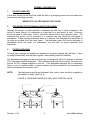
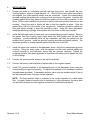
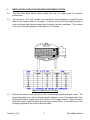
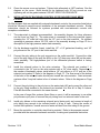
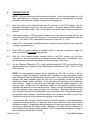
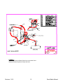
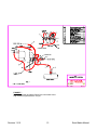
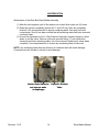
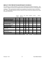
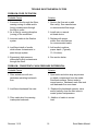
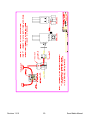
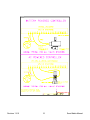
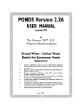
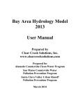
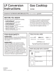
Sand Media Filter Installation Manual
Revision 11/10
1
Sand Media Manual
Table of Contents
Quick Start ………………………………………………………………
Page 3
General Information ……………………………………………………… Page 4
Tank Installation Instructions …..……………………………………….. Page 5
Media Installation ……….…….…………………………………………. Page 6
Control Installation ……………………………………………………….. Page 7
Start Up …………………………………………………………………… Page 8
Backwash Restrictor Adjustment ……………………………………….. Page 9
Notes on Backwash ……………………………………………………… Page 11
Water Stack Assembly Diagram Low Pressure …………………….. Page 12
Water Stack Assembly Diagram High Pressure ……………………… Page 13
Winterization ………………………… ………………………………….. Page 14
Preventive Maintenance Schedule …………………………………..
Page 15
Troubleshooting Guide …………………………………………………
Page 16
Filter Underdrain Blockage ……………………………………………..
Page 19
Solenoid Valve Wiring Diagram ………………………………………
Page 20
Revision 11/10
2
Sand Media Manual
Rain Bird Corporation
QUICK START INSTRUCTIONS
Sand Media Filter Installation and Start-up Overview
Concise, general directions for the experienced installer complete with detail references for the less
experienced.
1. Place filters in desired arrangement; two legs face front, one towards rear. Tanks should be on
centers of tank diameter +4”. Install outlet manifold. Ref. Page. 3
2. Install backwash valves, actuator faces front. Ref. Page. 4
3. Install inlet manifold. Ref. Page. 4
4. Wash gravel then install gravel and media to levels indicated on tanks. Ref. Page. 4
5. Install the water stack assembly on the inlet manifold. Ref. Page. 6
6. Poly tube discharge manifold to low pressure port on 3-way valve on water stack. Ref. Page. 6
7. Install solenoid valves on automatic valve actuator. # “1” port to valve (arrow on bottom of solenoid
valve should point toward backwash valve). Ref. Page. 6. Semi-automatic systems refer to diagram
on Page 21, then proceed to step 11 below.
8. Poly tube solenoid valve # “2” ports to water stack, poly tube remaining ports to drain. Ref. Page. 6
9. Install the backwash discharge manifold and backwash-throttling valve. These are installer
supplied items. Ref. Page 3
10. Install Control Box Stand and mount controller. Ref. Page. 7
11. Wire solenoids and pressure differential switch. Refer to controller manual. Set pressure differential
switch to 13 PSI. Ref. Page. 7
12. Gradually introduce water to the system and purge air from the system. Ref. Page. 7
13. Adjust the backwash-throttling valve to about 25% open. Ref. Page. 8
14. Manually backwash the system, open backwash throttle valve until a slight amount of media is
identified in the backwash stream. Adjust the valve slightly closed until only trace amounts of media
are detectable. Ref. Page. 8
15. Set the delay time on the controller by timing the time it takes a valve to go from the backwash
position back to the filter position. Set the delay time to the next time setting shorter than the valve
travel time. Ref. Page. 10
16. Set the backwash frequency by monitoring the time it takes the system to build a pressure differential
8 PSI greater than the clean system pressure differential. Set the periodic flush time to this time or
the next shorter time. The "time" function should be the primary backwash control function. Ref.
Page. 10
17. Set the backwash duration after the initial clean up. Set the duration for the time it takes clear water
to discharge from the backwash line. This should be a minimum of 90 seconds. Ref. Page. 10
System set up is now complete. Refer to the following complete manual for more detailed instructions
and troubleshooting guide.
SERVICE NOTE: PRESSURE IS REQUIRED TO BE RELEASED FROM THE
FILTER BEFORE PERFORMING ANY SERIVCE OR MAINTENANCE
OPERATION ON THE FILTER. WORKING ON A PRESSURIZED VESSEL CAN
CAUSE INJURY AND SHOULD NEVER BE ATTEMPTED FOR ANY REASON.
SERVICE FEE BASED SERVICE BY RAIN BIRD AUTHORIZED SERVICE
PROVIDERS IS AVAILABLE IN MOST AREAS.
Revision 11/10
3
Sand Media Manual
GENERAL INFORMATION
1.
ON-SITE HANDLING
A filter tank should only be lifted from under the tank or by strapping around the legs where they
join the tank, and lifting vertically.
NEVER LIFT A FILTER TANK BY THE VALVE!
2.
PROVISIONS FOR BACKWASH WATER DISCHARGE
Although the amount of water required to backwash the filter bed is small compared to the
amount of water filtered, it is discharged at a high rate for a short period of time. Provisions
should be made to drain away, store or otherwise dispose of the dirty backwash water. The
backwash line should not be connected to a pressure line and should be discharged to
atmosphere. When returning backwash water to a reservoir, the discharge point should be as
far away as possible from the pump intake. The backwash water flow should discharge to
atmosphere above the water, not underwater! This will allow for proper backwash flow
adjustment.
3.
FILTER COUPLINGS
Grooved type couplings are supplied as standard on all piping supplied with the filters. These
couplings mechanically lock the filters together, while allowing some line flexibility.
The backwash discharge ports have grooved type couplings with slip PVC adapters to facilitate
PVC backwash manifold installation. The backwash discharge line should be the same size
pipe as the PVC adapter supplied on the unit. If the backwash discharge line is excessively
long or runs on a downhill slope, a vacuum breaker should be installed on the backwash line
after the backwash flow restrictor valve.
NOTE:
The backwash manifold and backwash flow control valve should be supplied by
the installer or dealer. (See Fig. A)
FIGURE A. BACKWASH MANIFOLD AND FLOW CONTROL VALVE
GROOVE FOR COUPLING
BACKWASH FLOW CONTROL VALVE
PIONEER
BACKWASH
OUTLET
GROOVE FOR
COUPLING
INLET
OUTLET
Revision 11/10
4
Sand Media Manual
1.
INSTALLATION
1.1
Position the tanks on a concrete pad with two legs facing front, one towards the rear.
Position tanks on centers of tank diameter +4”. Once the filter tanks have been placed
and aligned, the outlet manifold should now be connected. Locate the corresponding
grooved coupling that matches the outlet spud size and remove the gasket. Lubricate the
coupling gasket with soapy water and slide the gasket onto the outlet connection on the
filters. Lift the outlet manifold into position so that the tank and manifold connections are
touching. Using floor jack or blocks will help to hold the manifold in place. Slide the
gasket down until it is in the center of the two grooves. Install the grooved coupling and
bolts and tighten enough to keep the manifold in place. Using the above procedure,
install the remaining couplings and re-tighten all of the bolts on the lower manifold.
1.2
Install the backwash valve on each tank using corresponding grooved coupling. Remove
the gasket from the coupling, apply soapy water and slide gasket onto the tank inlet
connection. Locate backwash valve on top connection and slide the gasket into the
middle of the 2 grooves. Install the grooved coupling and bolts and tighten partially. The
automatic actuator or manual operator should face the front of the filter.
1.3
Install the upper inlet manifold to the backwash valves, using the corresponding grooved
coupling. Using the soapy water, slide the gaskets onto the inlet manifold spuds and
connect manifold to the backwash valves with the grooved couplings. Tighten the
couplings partially, then check alignment of manifolds and valves and re-tighten the bolts
on all couplings.
1.4
Connect the incoming water supply to the top inlet manifold.
1.5
Connect the bottom outlet manifold to the field side of the irrigation system.
1.6
Install PVC grooved adapters to the backwash ports on the backwash valves using the
corresponding size grooved coupling. Complete the assembly of the backwash manifold
(installer/dealer provided). A backwash restrictor valve must be installed within 5 feet of
the last backwash valve for proper system operation.
NOTE: The flush restrictor valve is essential for the correct operation of a sand media
filter. Any gate, globe or butterfly valve is satisfactory if, after adjustment, the valve stem
can be locked in place to protect against accidental or inadvertent adjustment.
Revision 11/10
5
Sand Media Manual
2.
MEDIA INSTALLATION FOR RAIN BIRD SAND MEDIA FILTERS
2.1
The Rain Bird Sand Media Filters require the use of a gravel pack for optimum
performance.
2.2
The amount of 1/2" to 3/4" crushed rock and filtration media required to properly fill each
filter can be found in Table A, on page 6. Crushed rock must be thoroughly washed to
remove dirt and other foreign material that could plug the filter underdrain. The crushed
rock must cover the wedge wire underdrain by 2 to 3 inches.
TABLE A. MEDIA FILL LEVELS
2.3
Remove the access cover and pour in the recommended gravel pack and media. The
gravel pack goes in first with the filtration media loading in on top of the gravel pack. Prior
to filling with media, inspect inside of the filters for any foreign material. Filters should be
filled with media to approximately the level given in chart above. Do not allow any of the
packaging material to get mixed in with the media.
Revision 11/10
6
Sand Media Manual
2.4
Clean the access cover and replace. Tighten bolts alternately at 180o locations. See the
diagram on the cover. Bolts should not be tightened over 25 foot pounds as over
tightening will cut the gasket material. DO NOT OVER TIGHTEN BOLTS.
3.
INSTALLATION OF BACKWASH CONTROLS FOR RAIN BIRD SAND MEDIA
FILTERS
On filter systems that are supplied with automatic backwash controls, the procedure listed below
should be followed to assure correct installation of the automatic backwash controls. Similar
instructions should be followed for systems provided with semi-automatic controls with
exceptions noted below.
3.1
The water-stack is shipped pre-assembled. An assembly diagram for future reference
can be found on Page 12. The water stack is connected to the inlet manifold (upper)
screwing the 1/2" male ball valve into the 1/2" port on the inlet manifold. On systems
operating at pressures above 100 PSI, refer to the assembly drawing on Page 13 for a
description of the high-pressure water stack assembly.
3.2
On the discharge manifold (lower), install the 1/2" x 1/4" galvanized bushing, and 1/4"
poly elbow into the 1/2” port in the outlet manifold.
3.3
Connect the poly tubing to the poly connector on the outlet manifold. Connect the other
end of the poly tubing to the poly tee (#5A) on the 1/4” three-way valve (#8) on the waterstack assembly. The high-pressure port of the differential pressure switch is factory
assembled.
3.4
Install the solenoid valves to the valve actuators. The solenoid port marked 1 is
connected to the 1/4" port on the valve actuator with a 1/4" close nipple. Depending on
the number of backwash valves, install either a 1/4" poly elbow or a 1/4" poly tee to the
solenoid port marked 2. Refer to the diagram on Page 12. The flow arrow on the bottom
of the base of the solenoid valve should point toward the valve actuator. Semi-automatic
systems utilize 3-way ball valves in lieu of solenoid valves. Refer to the diagram on Page
21.
3.5
Connect the poly tubing to the poly tee on the water-stack (#5) and connect the other end
to the poly fitting installed to the solenoid port marked 2 on filter #1 in Step 3.4 above.
Filter #2 should be connected in the same manner.
In the case of larger filter systems (three filters or more), it will be necessary to use either
poly elbows or poly tees to connect the poly tubing from one solenoid valve to the next.
3.6
Install poly elbows on the remaining solenoid ports (drain ports) and connect a length of
poly tubing long enough to be inserted inside of a leg of tank. During the course of
normal filter operation, a small amount of water will drain from this tubing to the ground.
3.7
Mount the controller to controller stand that is provided. Refer to the separate manual
provided with the automatic backwash controller for wiring and operational instruction.
Revision 11/10
7
Sand Media Manual
4.
SYSTEM START-UP
NOTE: First time start-up should be done with caution. All air must be purged out of all
lines and filters prior to start-up. Valves and pumps must be opened slowly to prevent
damage to filters and the irrigation system due to entrapped air.
4.1
Start the system in the manual mode with the controller in the OFF position, with the
backwash restriction valve in the 1/4 open position. Introduce water into filter system,
filling lines and tanks slowly. The 1/2" ball valve on the water stack should be in the open
position.
4.2
When approximately 10 PSI pressure is reached, turn the manual override knob on the
solenoid on tank #1 to the ON position for 1 to 2 minutes to purge entrapped air from the
system. Turn tank #1 OFF and repeat this process on tanks #2, 3, 4, etc.
4.3
When 50% of the system operating pressure is reached, repeat the flush cycle manually
to purge any remaining air.
4.4
When 100% of system pressure is reached or after 15 minutes of operation, repeat the
flush cycle allowing 3 minutes flush per tank.
4.5
With all of the solenoid manual override knobs in the OFF position, turn the flush
controller on. Set the flush time to 90 seconds and the delay time to 30 seconds. Push
the manual start button and the system should go through a flush cycle.
4.6
Set the Pressure Differential (P.D.) switch pointer/contact at 8 PSI over the clean filter
pressure differential. (Example: Clean filter pressure differential of 5 PSI + 8 PSI = 13 PSI
switch setting).
NOTE: On high-pressure systems (those operating at 100 PSI or more), it will be
necessary to adjust the pressure regulator that is supplied on the high-pressure water
stack assembly to permit the backwash valves to open. As soon as the system operating
pressure has been reached loosen the lock nut on the regulator handle and turn the
adjustment handle counter clockwise. This will reduce the pressure on the backwash
valve actuator. Then, put one valve into backwash using the manual override on the
solenoid valve. Slowly turn the adjustment handle on the regulator clockwise, which
increases the pressure on the backwash valve. Slowly continue increasing the pressure
until the backwash valve opens smoothly and completely. Excessive pressure on the
valve actuator could result in the backwash valve opening too fast creating water hammer
and possible valve damage. Insufficient pressure will not allow the valve to open fully.
Tighten the locking nut once the pressure regulator is set properly.
4.7
The automatic filter controller should be set so that the frequency of filter backwashing
corresponds with the build up of pressure drop to the established dirty filter pressure
differential set point. Establishing the time frequency of flush may require several days of
monitoring to determine the proper setting. (Example: If it takes 6 hours of operation to
reach the dirty filter pressure switch setting of 13 PSI, the backwash frequency setting on
the controller should be set at 6 hours).
Revision 11/10
8
Sand Media Manual
4.8
The backwash restrictor valve adjustment - The most critical factor to proper sand filter
operation!
4.8.a. Open the backwash restrictor control valve approximately 25%.
4.8.b. Be sure that all air is purged from each tank by partially opening and closing each tank
flush valve.
4.8.c. Before proceeding with backwash adjustments, the pump must be run long enough to fill
the entire irrigation system at the designed pressure and flow.
4.8.d. Manually initiate a backwash on one tank by turning the manual override screw to the
“ON” position. With semi-auto systems turn the 3-way ball valve on backwash valve to
introduce water into the valve actuator.
4.8.e. By the use of hand sampling, use of a clear jar or a screen-sampling device, monitor the
contents of the backwash discharge water.
4.8.f. Gradually open the backwash restrictor valve until a small amount of media from the
backwash water appears in the discharge flow.
4.8.g. When media begins to show up in the backwash water, close the backwash flow control
valve until the water is essentially clear of media. A small trace of media is acceptable
since it is desirable that the lighter granules (fines) in the bed be allowed to wash out.
After completing the above adjustments, all tanks should be backwashed extensively (3
to 5 minutes each) to remove contaminants and fine material usually found in newly
installed media.
Revision 11/10
9
Sand Media Manual
RECOMMENDED BACKWASH FLOW RATES BY TYPE OF MEDIA
The following table shows the approximate backwash flow rates that are required to provide for
proper filter backwash. All factors are per single tank. Actual backwash flow should be
determined as described in Section 5. Use of a flow meter for setting of backwash restrictor
valve is not recommended.
Media Type
Mean Eff.
Media Size
Uniformity
Coefficient
S-47 #20 Silica
G-78 #11 Granite
.47 mm
.78 mm
1.42
1.54
Approximate Backwash Flow Rate
(GPM) By Filter Size
18” 24” 30” 36” 48”
25 50 80 110 200
25 50 80 110 200
During backwash, the tanks not being backwashed supply clean water for
backwashing, and also supply the filtered water for the field. If the volume of your
source water is not adequate for both the backwash requirement and to supply
filtered water to the field, you can increase the backwash flow by installing a valve
in the filtered water output line and closing off or partially restricting the flow
through this line during backwash. If this method is used, the flow must be
restricted exactly the same amount each flush or variable backwash performance
will occur.
5.
THE BACKWASH FUNCTION
Backwashing the filters is the process by which clean water flows upward through the
underdrain, lifting and expanding the media bed allowing it to release the collected contaminate.
The contaminant is then carried away with the backwash water. Excessive backwash flow rates
will expand the media to the point that the media itself is expelled out of the tank. Insufficient
backwash flow will not expand the media enough to purge all the entrapped contaminant. This
Revision 11/10
10
Sand Media Manual
could result in a residual pressure loss through the bed, even after backwash. To achieve
maximum filter performance, the backwash flow must be properly adjusted.
IMPORTANT NOTES:
1.
2.
3.
If at a later time, you make any significant changes in pressure or flow, the above
adjustments should be re-checked.
Backwashing at 8 PSI above clean filter pressure differential is recommended.
The minimum stated system operating pressure is 20 PSI. When operating at pressures
lower than 40 PSI, pay especially close attention to the backwash function to ensure
adequate cleaning. An effective backwash requires that back-pressure be maintained on
the system during backwash. A pressure maintenance valve may be required.
Backwashing should be more frequent on low-pressure (<40PSI) applications, with an
allowable increase in pressure differential, over clean, of 5 PSI.
The backwashing function of the sand media filtration system is the most important aspect of the
filter system operation. Without proper backwashing, the entrapped dirt is not expelled from the
system. Filters should be flushed when the pressure loss increases by 8 PSI over the clean
filter pressure loss. Each filter should be flushed for a minimum of 90 seconds per tank. If
backwash water is not visually clear after 90 seconds time, extend the flush duration. Filters
should be flushed for a minimum of 90 seconds each, at least once every 24 hours even if an 8
PSI pressure drop is not attained. The dwell setting is properly set when there is a slight overlap
of two filters flushing. Measure the time required for a valve to return to the filter position from
the backwash position. Set the dwell setting to the next shortest setting. The quality of product
water produced by your sand media filters is directly affected by the quality and frequency of the
backwashing operation. In filters utilizing the wedgewire underdrain some contamination build
up may occur where heavy silt loading is present. Under these circumstances a periodic longer
backwash cycle or mechanical agitation of the sand bed may be required.
Revision 11/10
11
Sand Media Manual
FIGURE E –
Hydraulic Actuator and Water Stack for the Automatic Valve
Standard Pressure Systems 100 psi and lower
Revision 11/10
12
Sand Media Manual
FIGURE F –
Hydraulic Actuator and Water Stack for the Automatic Valve
High Pressure Systems above 100 psi
Revision 11/10
13
Sand Media Manual
WINTERIZATION
Winterization of the Rain Bird Sand Media Assembly
(1) After the last irrigation cycle of the season run a back-flush cycle two (2) times.
(2) Drain the system completely (ensure all ¼” and 3/8” poly lines are completely
drained). Use compressed air to remove remaining water from poly lines and
components. Once it has been verified that all remaining water has been removed,
reconnect lines.
(3) Loosen the fasteners on the 3- Way Solenoid Hydraulic Actuator flanges to allow
water to exit the valve. Remove (via quick connect fitting) ¼” poly tubes from
solenoids and blow remaining water out of the solenoid (replace poly tubes when
complete). Use compressed air to ensure any remaining water is removed.
NOTE: Any remaining water that can freeze in a contained area will cause damage.
Complete removal of water is critical to avoid damage.
Loosen these fasteners
and remove water
in diaphragm
Revision 11/10
14
Hydraulic Actuator
Valve
Sand Media Manual
MEDIA FILTER PREVENTIVE MAINTENANCE SCHEDULE
The following is a simple schedule for start-up and operational preventative maintenance. The
format is a simple one that can be adapted to all forms of filtration and even to other agricultural
equipment. The chart should be located in an accessible, but protected, location on the filter
pad. The responsible individual should be instructed to date and sign the respective block after
each task is performed.
Seasonal
Seasonal
start up
shut down
Winterization
Bi-Monthly
Monthly
X
Clean water pickup assembly filter
X
Inspect all poly line connections.
X
Inspect elec.con. & control box seals.
X
Lubricate backwash valve.
X
Inspect inner valve components
(seals,diaphram & shaft.)
Quarterly
X
X
X
X
X
Check coupling gaskets for leaks.
X
Check system pressure diff.
X
Adjust backwash flow rate.
X
Check flowmeter to assure
proper flow rate
X
Monitor duration of flush cycle.
X
X
X
X
X
X
X
Evaluate seasonal water
quality fluctuations
Service down stream strainer
Revision 11/10
Weekly
X
Check media depth
Chlorine shock treatment.
Daily
X
X
X
X
15
Sand Media Manual
TROUBLE SHOOTING MEDIA FILTERS
PROBLEM: POOR FILTRATION
Probable Cause
Solution
1. Excessive flow through the filters,
causing coning of media and/or
forcing contaminants through
the filter to outlet.
2. Air in filter(s) causing disruption
(coning) of the media bed.
1. Reduce the flow rate or add
filter unit(s). See manufacturer
or recommended flow range.
3. Incorrect media in the filtration
system.
3. Replace with proper
media. See manufacturer
for recommended media.
4. Insufficient depth of media,
which allows contaminants to
pass through system.
5. Add media to achieve
proper depth. (Typically
13-14 inches).
5. Excessively high pressure
differential forcing contaminants
through the filters.
4. See section below.
2. Install auto or manual
air bleed device.
PROBLEM: CONSISTENTLY HIGH PRESSURE DIFFERENTIAL
Probable Cause
Solution
1. Filter sealed over with contaminates restricting backwash
flow.
1. Open tanks and skim away any excess
or caked contaminants from the media
Sand beds surface. Return tanks to
normal service. Backwash each filter tank
until backwash flow runs clean.
2. Insufficient backwash flow rate.
2. Readjust the backwash restrictor valve
and/or partially close the field valve to
create system backpressure.
3. Filter media level low causing
inadequate backwash.
3. Addition of media to correct
level.
Revision 11/10
16
Sand Media Manual
PROBLEM: MEDIA SAND APPEARS DOWNSTREAM
Probable Cause
Solution
1. Incorrect filter media sand
i.e. too fine).
1. Replace with the proper media
sand. See manufacturers
recommendations.
2. Broken or damaged underdrain.
2. Repair or replace.
PROBLEM: BACKWASH VALVE(S) LEAK
Probable Cause
Solution
1. Obstruction in valve seat.
1. Remove obstruction.
2. Polyurethane sealing disk is worn
or damaged.
2. Replace valve seal.
3. Diaphragm damaged (leaking
from port of diaphragm chamber
at rear of valve).
3. Replace diaphragm.
4. Pinched or worn O-Ring.
4. Replace O-Ring and/or
lubricate shaft.
PROBLEM: WATER HAMMER
Probable Cause
Solution
1. Air in tanks.
1. Bleed off trapped air.
See start-up instructions.
Also check for leaks in the
pump suction line. An air
bleed at the filter inlet may
also help.
2. Long backwash line causing
vacuum induced slamming of
valves.
2. Install a vacuum breaker on
the backwash line.
Revision 11/10
17
Sand Media Manual
PROBLEM: INCREASING FREQUENCY OF BACKWASH CYCLE
Probable Cause
Solution
1. Backwash flow or duration is
not adequate to flush filter
tanks of all contaminants.
1. Readjust backwash flow
and/or increase duration
of backwash cycle.
2. Insufficient media depth.
2. Add media sand to achieve
proper depth.
3. Increased concentration of
contaminants in water supply.
(Note: May only be a seasonal
problem.)
3. Add extra filter tank(s)
to system or reduce flow rate.
PROBLEM: AUTOMATIC BACKWASH FAILS TO CYCLE
Probable Cause
Solution
1. Controller power off,blown
fuse or circuit breaker
tripped.
1. Turn power on. Be sure wiring is
connected. Reset circuit breaker or
install new fuse.
2. Improper setting on
differential pressure switch.
2. Inspect seal for signs of
tampering.
3. Solenoid(s) malfunctioning.
4. Loss of sufficient system
pressure to actuate valve(s).
Revision 11/10
3. Check connections. Clean ports.
Check filter screen on water
pickup assembly for damaged screen and
clean or replace if necessary.
4. Check system for pressure leaks. Also,
inspect filter screen on water pickup
assembly for damaged screen. Clean or replace if necessary.
18
Sand Media Manual
FILTER UNDERDRAIN OBSTRUCTION OR BLOCKAGE
Infrequent flushing, the lack of chemical treatment, an improperly set backwash restrictor valve
or operating the filters outside of the recommended flow range are the four most common
causes of media filter underdrain blockage. All four of these situations, either singularly or in
combination, will result in contaminants reaching and possibly fouling the filter underdrain.
Evidence of underdrain blockage can be seen by monitoring the pressure gauges. If the
pressure differential does not return to 2-6 PSI after a flush cycle there is a possibility of
underdrain contamination.
First, the cause of the blockage must be determined and rectified (i.e. reset the backwash
restrictor valve, increase the frequency of flushing, adjust the flow rate to comply with the
manufacturer's recommendation or install chlorine injection equipment.) If the cause of the
blockage has been identified and corrected, and the pressure differential does not return to 2-6
PSI after backflushing, more severe steps will have to be taken to clear the underdrain. If
organic contaminants are suspected, a chlorine shock treatment may be necessary.
Step 1:
Step 2 :
Step 3:
Step 4:
NOTE:
CHLORINE SHOCK TREATMENT FOR SAND MEDIA FILTERS
Remove filter manway lids and fill each tank with water up to the top weld seam. It
is not necessary to remove the sand. Make sure that the field valve is closed so
water will be held in the filter tanks.
Add 10 to 20 ounces of 12% pool chlorine per square foot of filtration area to each
vessel. If unavailable, double the amount of chlorine bleach is an acceptable
alternative.
Allow to stand for 12 hours. BEWARE OF CHLORINE FUMES.
Secure manway lids, open the field valve and initiate a backflush cycle. Flush each
vessel for approximately 3 minutes and repeat the full sequence several times.
One or two shock treatments will usually be enough to unplug an underdrain that
is contaminated with organics. Consult the manufacturer if a high-pressure
differential persists.
SAFETY NOTE:
Always wear eye protection, gloves and protective clothing whenever handling any chemicals.
A safety water rinse station should also be available to rinse off any chemicals, which may come
into contact with filter personnel. Do not mix with other
chemicals in this procedure and always induce chemicals into a water filled filter tank
Revision 11/10
19
Sand Media Manual
Revision 11/10
20
Sand Media Manual
Revision 11/10
21
Sand Media Manual