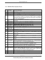
1
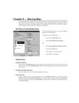
DVI-250 System Operation and Installation Manual
DOC0111
Applies to the following PN:
DVI-250A, DVI-250C, DVI-250AP, DVI-250CP,
Document Revision: 01.007
May 01, 2009
SkyTrac Systems Ltd.
200-170 Rutland Rd, N
Kelowna, BC, Canada
V1X 3B2
Tel. (250) 765-2393
Fax (250) 765-3767
Web: www.skytrac.ca
Email: [email protected]
Copyright © 2007 SkyTrac Systems Ltd.
All rights reserved.
SkyTrac Systems Ltd.
Engineering Approval:
Date:
Management Approval:
Date:
Document Revision History
Rev
ECO Pg
01.000 096
01.001
111
6
01.002
107
19
01.003
136
01.004
146
1,2,5,
11,15,
16
9, 20
01.005
147
8
01.006
166
1,8
01.007
169
1,8
Description
Initial Release Mod A
Date
Jan.31,
2007
Author
T. Ratch,
V. Roslov
A. Ramalingam
V. Roslov
Added DO-160E
category
Added reference to
DOC0029 (Optional
Equipment Wiring
Diagram)
Added information on
push button ISAT
EMERG switch option
Changed reference to
Installation drawings
Updated max. min.
operating voltages
Updated statement
applies to and add
section 3.3 DVI-250
Installation Kit
Add reference to
DOC0170
Jul.16,
2007
Aug.22,
2007
T. Ratch
V. Roslov
T. Ratch
Nov. 26,
2007
D. McMahon
L. Wyspinski
T. Ratch
July 28,
2008
July 29,
2008
Feb, 23,
2009
A. Parker
T. Ratch
A. Parker
T. Ratch
A. Parker
T. Ratch
May 01,
2009
D. McMahon
T. Ratch
Document Rev. 01.007
DOC0111
Restricted Proprietary and Confidential Information
Approval
T. Ratch
Page 2 of 20
SkyTrac Systems Ltd.
Table Of Contents
1
About this Document ....................................................................................................5
1.1
1.2
1.3
2
General ...........................................................................................................................5
2.1
2.2
2.3
2.4
3
Purpose .....................................................................................................................5
Scope ........................................................................................................................5
Definitions, Acronyms, Abbreviations ........................................................................5
Introduction ...............................................................................................................5
Description ................................................................................................................5
Purpose of Equipment...............................................................................................6
System Requirements ...............................................................................................6
Specifications ................................................................................................................7
3.1 Physical Properties ...................................................................................................7
3.2 Technical Specifications ............................................................................................7
3.2.1 Optical Specifications .........................................................................................7
3.2.2 Electrical Specifications ......................................................................................8
3.3 DVI-250 Installation Kit ..............................................................................................8
4
Airworthiness Limitations ............................................................................................8
4.1
4.2
5
Installation Limitations ...............................................................................................8
Operating Limitations ................................................................................................8
INSTALLATION INSTRUCTIONS ..................................................................................9
5.1 Installation Requirements ..........................................................................................9
5.2 Unpacking and Inspecting .........................................................................................9
5.2.1 Identifying Your DVI-250.....................................................................................9
5.2.2 Equipment Packing Log ......................................................................................9
5.3 Installation Wiring ......................................................................................................9
5.3.1 DVI-250 25 Pin Connector Pin-out. ..................................................................10
5.3.2 DVI-150 Upgrade to DVI-250 (working in DVI-200-Compatibility Mode) ..........11
5.3.3 DVI-150 Upgrade to DVI-250 (Working in Normal Mode thru RS485) ..............11
5.3.4 DVI-200 Upgrade to DVI-250 (working in DVI-200-Compatibility Mode) ..........11
5.3.5 DVI-200 Upgrade to DVI-250 (working in Normal Mode thru RS485)...............11
5.4 DVI-250 Installation .................................................................................................11
5.4.1 Check Contents ................................................................................................12
5.4.2 Bright/DIM Control Method (DVI-250 mode only) .............................................12
5.4.3 Wiring Harness .................................................................................................13
5.4.4 Product Mounting .............................................................................................13
5.5 DVI-250 Post Installation Test .................................................................................14
5.5.1 Function Test Setup .........................................................................................14
5.5.2 Function Test ....................................................................................................14
5.5.3 EMI Test ...........................................................................................................15
6
Maintenance and Continued Airworthiness..............................................................18
6.1
Continued Airworthiness .........................................................................................18
Document Rev. 01.007
DOC0111
Restricted Proprietary and Confidential Information
Page 3 of 20
SkyTrac Systems Ltd.
6.2
Maintenance Instructions ........................................................................................18
7
Appendix A Mechanical Diagrams.............................................................................19
8
Appendix B Installation Diagrams .............................................................................20
Document Rev. 01.007
DOC0111
Restricted Proprietary and Confidential Information
Page 4 of 20
SkyTrac Systems Ltd.
1
1.1
ABOUT THIS DOCUMENT
Purpose
This document provides information and specifications required for installation of the DVI250.
1.2
Scope
This document is intended for DVI-250 installers and operators.
1.3
Definitions, Acronyms, Abbreviations
Acronym
STS
DVI
CDP
PCB
2
2.1
Description
SkyTrac Systems Ltd.
Dispatch Voice Interface
Cockpit Display Panel
Printed Circuit Board
GENERAL
Introduction
This publication provides technical information for the DVI-250 Sat/Com control head. The
DVI-250 provides a sat-phone and pre-programmed text message interface to SkyTrac
Systems’ ISAT-100.
The DVI-250 can also be interfaced to the CDP-250 Cockpit Display Panel to provide full 2way text message support.
SkyTrac System’s Iridium based ISAT-100 combined with the DVI-250 provides true global
voice and text communications.
2.2
Description
The DVI-250 has a small, easy to use form factor well suited to the demanding environment
of working aircraft.
The DVI-250 consists of a DZUS rail mounted keypad, a number of indicators and a locking
toggle or push button switch. The keypad is used to dial numbers and send preprogrammed text messages. The indicators indicate incoming calls, text messages, ISAT
communications status and errors. A front panel locking toggle switch or push button switch
is used to trigger the ISAT emergency mode.
Document Rev. 01.007
DOC0111
Restricted Proprietary and Confidential Information
Page 5 of 20
SkyTrac Systems Ltd.
The two models DVI-250C DVI-250A are identical other than the NVIS classification. DVI250C is a commercial grade Night Vision Goggle (NVG) Friendly Green backlit panel. DVI250A is a NVIS A Night Vision Goggle (NVG) Compliant panel.
The two models DVI-250CP, and DVI-250AP, are identical to the DVI-250C and DVI-250A
models except a pushbutton switch is used in place of a locking toggle switch for activation
of the ISAT Emergency mode.
2.3
Purpose of Equipment
The DVI-250 is designed to provide an easy to use interface to the ISAT-100.
The
interface enables the user to make Sat phone calls by either dialling the complete number
or using quick dial list.
Pre-programmed text messages are also supported, allowing users to get important
information to the ground in an efficient and timely manner without distraction from the
mission.
Thru its interface to SkyTrac’s ISAT-100, the DVI-250 enables the user to send preprogrammed text messages and dial pre-programmed and manual phone numbers from
anywhere in the world.
2.4
System Requirements
The DVI-250 requires an ISAT-100 with up-to-date firmware to operate.
Document Rev. 01.007
DOC0111
Restricted Proprietary and Confidential Information
Page 6 of 20
SkyTrac Systems Ltd.
3
SPECIFICATIONS
DVI-250A MOD A and DVI-250C MOD A are qualified to the DO-160E environmental
category
[(A1)(F1)]-CXB[(SBM)(UG)]XXXXXXZBBXXXMXXXX
3.1
3.2
Physical Properties
Operating Temperature
-15ºC to +55ºC
Size
L: 3.4” (86 mm) excluding connectors and emergency
switch
H: 1.12” (28.4 mm)
W: 5.75” (146 mm).
Weight
0.27kg (0.6 lbs)
Mounting
DZUS rails using 4 1/4 Turn Studs.
Cooling
Normal air circulation required.
Technical Specifications
3.2.1 Optical Specifications
Indicators Brightness:
Day Mode: 150 fl Minimum.
Night Mode: (dimmable from Day Mode)
Backlighting Brightness
Day Mode: NA
Night Mode: 1 fl +/- 0.5 fl (dimmable)
Display colours:
Indicators
DATA DELAY
Activity
MSG IN
Panel Backlighting Green
DVI-250C
Yellow
Green
Green
Green
DVI-250A
NVIS Yellow A
NVIS Green A
NVIS Green A
NVIS Green A
Document Rev. 01.007
DOC0111
Restricted Proprietary and Confidential Information
Page 7 of 20
SkyTrac Systems Ltd.
3.2.2 Electrical Specifications
Power Requirement:
Nominal standard 28VDC system bus via 3 Amp breaker.
*Actual consumption is 0.03 Amp typical, 0.05 Amp
while indicators are on. (Equipped with reverse voltage
and transient protection).
Maximum Supply Voltage +32.2V DC
Nominal Supply Voltage +27.5V DC
Minimum Supply Voltage +20.5V DC
Abnormal surge voltage
3.3
+40.0V DC for 100 msec.
+37.8V DC for 1 sec.
DVI-250 Installation Kit
The Installation Kit for the DVI-250 is PN: STS0011. The parts contents of the Installation Kit
can be found in the latest revision of the DVI-250 Installation Kit Bill of Materials
(DOC0170). It contains mating connector to the DVI-250, back shell and necessary
hardware to attach it.
4
4.1
AIRWORTHINESS LIMITATIONS
Installation Limitations
No Installation Limitations identified.
4.2
Operating Limitations
No Operating Limitations identified.
Document Rev. 01.007
DOC0111
Restricted Proprietary and Confidential Information
Page 8 of 20
SkyTrac Systems Ltd.
5
INSTALLATION INSTRUCTIONS
IMPORTANT NOTICE: All system interconnects cables must be connected before
power is applied to the system.
5.1
Installation Requirements
When installing the DVI-250 the installer must have a working knowledge of aircraft
electronics installation, and be a holder of either an FAA Repairman’s Certificate or a
Transport Canada equivalent. All installations should meet the requirements of FAA
advisory circular AC43.13-1B.
5.2
Unpacking and Inspecting
5.2.1 Identifying Your DVI-250
Refer to the MOD Status of your DVI-250. This label is placed on the chassis of the DVI250. If the MOD Status of your DVI-250 does not match the MOD Status on the title page
of this document, please obtain the SOI that applies to your unit from SkyTrac Systems.
5.2.2 Equipment Packing Log
Save the original shipping container in case of need for return due to damage or warranty
claims. Check that each item listed on the packing slip has been shipped in the container.
Verify and record the Serial Number of the DVI-250. This information is required when
contacting SkyTrac Systems to activate the satellite communications services.
5.3
Installation Wiring
The DVI-250 has two rear connectors, a 25 pin system connector and a 9 pin programming
connector.
The DVI-250 is fully backwards compatible with DVI-200 installations. A DVI-250 can be
placed into a DVI-200 installation and it will function as a DVI-200. This is referred to as
DVI-200 compatibility mode. In this mode the DVI-200 wiring harness is used to
communicate to the ISAT-100. The RS485 wiring is required to support the CDP-250.
The DVI-250 can also be installed to communicate to the ISAT over an RS485 link. The
wiring for this mode is much simpler than the DVI-200 compatibility mode.
Please see relevant STC drawings, or if an STC is not applicable, see pages 8, 9 of the
latest approved revision of “ISAT-100 Optional Equipment Wiring Diagram” (DOC0029).
Document Rev. 01.007
DOC0111
Restricted Proprietary and Confidential Information
Page 9 of 20
SkyTrac Systems Ltd.
5.3.1 DVI-250 25 Pin Connector Pin-out.
Pin
#
1
2
3
4
5
6
7
8
9
10
11
12
13
14
15
16
17
18
19
20
21
22
23
24
25
Pin Name
Function/Description
Ground
Reserved
28V
DIM CTRL IN
DVI-250 Ground Pin
Reserved for future use - Do not connect.
Connect to 28V.
Input to DVI-250 from aircraft for controlling Bright/Dim mode. Signal
may be analog or digital, to a maximum of 28V. Refer to installation
instructions and wiring diagram from more information. This pin has a
15k ohm input impedance.
DIM
CTRL Output from DVI-250 to ISAT-100 for bright / Dim control, 20V
OUT
maximum.
KEY OUT 0
Keypad Analog Output from DVI-250 to ISAT-100.
KEY OUT 1
Keypad Analog Output from DVI-250 to ISAT-100.
KEY OUT 2
Keypad Analog Output from DVI-250 to ISAT-100.
KEY OUT 3
Keypad Analog Output from DVI-250 to ISAT-100.
Send Key
Voltage Sourcing Output from DVI-250 to ISAT-100.
BRT/DIM
Input to DVI-250 from ISAT-100.
Mode CTRL
Reserved
Reserved for future use - Do not connect.
Ground
DVI-250 Ground Pin
RS-232 RX
RX line of RS-232 Databus to CDP-250. Do not connect if CDP-250
is not used.
RS-232 TX
TX Line of RS-232 Databus to CDP-250. Do not connect if CDP-250
is not used.
RS-485+
RS-485+ line to ISAT-100 (not required in DVI-200 compatibility
mode)
RS-485RS-485- line to ISAT-100 (not required in DVI-200 compatibility
mode)
Send Annun. Ground Seeking Input to DVI-250 from ISAT-100. Controls activation
of send annunciator in DVI-200 compatibility mode.
Delay Annun. Ground Seeking Input to DVI-250 from ISAT-100. Controls activation
of Data Delay annunciator in DVI-200 compatibility mode.
MSG Annun. Ground Seeking Input to DVI-250 from ISAT-100. Controls activation
of MSG IN annunciator in DVI-200 compatibility mode.
Reserved
Reserved for future use - Do not connect.
ISAT EMERG Current Sinking output from DVI-250 to ISAT-100. Activating this
output via the ISAT EMERG / NORM Switch (toggle or push button
type) places the ISAT into ISAT Emergency mode.
Reserved
Reserved for future use - Do not connect.
Reserved
Reserved for future use - Do not connect.
Reserved
Reserved for future use - Do not connect.
Document Rev. 01.007
DOC0111
Restricted Proprietary and Confidential Information
Page 10 of 20
SkyTrac Systems Ltd.
5.3.2 DVI-150 Upgrade to DVI-250 (working in DVI-200-Compatibility Mode)
A DVI-150 installation is upgradeable to the DVI-250 installation in DVI-200 compatible
mode with some minor wiring additions.
-
Wiring for Dimmer control must be added. Refer to Pins 4 and 5 in DVI-200 Wiring
Instructions (STS Document Number DVI-200-SYS-DIAG) for more information.
Your ISAT will also need to be configured to operate with the DVI-250. Please
contact SkyTrac to have your ISAT remotely configured.
5.3.3 DVI-150 Upgrade to DVI-250 (Working in Normal Mode thru RS485)
The DVI-150 wiring could be replaced with DVI-250 RS-485 wiring interface.
-
The wire between pins 15 and 17 must be removed.
Positive wire of RS485 interface must be connected to pin 16
Negative wire of RS485 interface must be connected to pin 17
Remaining wires can be left in place without affecting DVI operation, or they can be
removed or tied off and capped.
If both the DVI-200/150 and DVI-250 R485 wiring interfaces are present, the DVI 250
will use the DVI-250 RS485 interface by default.
Refer to pages 8 and 9 of DOC0029 (ISAT-100 Optional Equipment Wiring Diagram)
for details.
5.3.4 DVI-200 Upgrade to DVI-250 (working in DVI-200-Compatibility Mode)
-
-
For the installation where the 28V voltage was applied to pin #25 of the DB-25
connector (as per installation diagram of DVI-200, page 2): Change of wiring is not
necessary.
For the installation where the dimmer bus was applied to pin #2 (the brightness was
following the voltage on the dimmer bus), the dimmer voltage must also be applied to
the pin #4 (as per installation diagram of DVI-200, page 1).
5.3.5 DVI-200 Upgrade to DVI-250 (working in Normal Mode thru RS485)
-
5.4
Positive wire of RS485 interface must be connected to pin 16
Negative wire of RS485 interface must be connected to pin 17
Refer to pages 8 and 9 of DOC0029 (ISAT-100 Optional Equipment Wiring Diagram)
for details.
DVI-250 Installation
The main tasks for this installation are listed below:
Document Rev. 01.007
DOC0111
Restricted Proprietary and Confidential Information
Page 11 of 20
SkyTrac Systems Ltd.
1. Check the contents of the shipping container.
2. Determine the location of the DVI-250.
Note:
Some factors to be considered to determine install location including
ease of access, viewing angle and the affect of glare.
3. Determine if you want to connect the DVI-250 in DVI-250 mode or DVI-200
compatibility mode. The DVI-250 mode provides improved messaging and calling
features and it is the recommended mode.
4. Create the wire harness for the DVI-250 as determined in the previous step. For
wiring instructions refer to page 8 of DOC0029 (ISAT-100 Optional Equipment
Wiring Diagram) for DVI-250 mode, and page 9 of DOC0029 for DVI-200
compatibility mode.
5. Mount the DVI-250 using the DZUS fasteners.
6. Contact SkyTrac Systems to have them remotely activate your DVI and program
the text messages. The DVI-250 interface allows you to program the quickdial
numbers. Refer to the DVI-250 User’s Guide for details. If you are operating in
DVI-200 mode, contact STS to program the quick dial numbers.
7. Complete the Post installation test.
5.4.1 Check Contents
Check the contents of the shipping container as per Section 5.2 Unpacking and Inspecting.
5.4.2 Bright/DIM Control Method (DVI-250 mode only)
5.4.2.1 Day (Bright) and Night (Dim) Mode Configuration
If the DVI-250 is operating in DVI-200 compatibility mode, please refer to the DVI-200-OPDSOI for instructions on how to control the bright/dim mode.
The DVI-250 has two brightness modes - bright (day) and dim (night) mode – with
brightness settings preset for day-time and night-time flying conditions respectively. The
DVI-250 can be wired to the aircraft dimmer bus so that it can switch seamlessly between
these modes based on the aircraft cabin lighting.
The DVI-250 monitors the pin DIM_CTRL_IN pin (pin #4) voltage to decide if it is in bright
(day) or dim (night) mode. When the voltage is below a threshold voltage called bright mode
threshold, the DVI-250 is in bright mode. When the voltage is above a threshold voltage
called dim mode threshold, the DVI-250 is in dim mode. The DVI-250 uses a hysteresis
window to switch between these two modes. If the DVI-250 is in bright mode, it will switch to
dim mode only when the voltage increases above the dim mode threshold. If the DVI-250 is
in dim mode, it will switch to bright mode only when the voltage falls below the bright mode
threshold.
There are two possible ways to connect the DIM_CTRL_IN (pin #4).
Document Rev. 01.007
DOC0111
Restricted Proprietary and Confidential Information
Page 12 of 20
SkyTrac Systems Ltd.
1. If DIM_CTRL_IN is left unconnected, the DVI-250 will always be in bright (day) mode.
2. If DIM_CTRL_IN is connected to the aircraft dimmer bus then the DVI-250 can switch
modes based on the aircraft dimmer bus voltage. For example when the aircraft
cabin lights are off, the dimmer bus voltage is zero and the DVI-250 goes to day
(bright) mode. When the lights are ON, the dimmer bus voltage is positive and when
the voltage increases above the dim mode threshold, the DVI-250 goes to dim (night)
mode. In the night mode, the backlighting brightness of the key pad buttons follows
the aircraft dimmer bus voltage.
Parameter
DIM_CTL_IN – Max Voltage
Dim mode threshold
Bright mode threshold
Value
28 Volts
1.3 Volts
0.7 Volts
The brightness for the indicators (Activity light, Data delay, and Msg In) and backlighting for
the keys can be controlled separately.
5.4.2.2 Indicators
The indicators are turned ON to full brightness in bright (day) mode. In dim (night) mode, the
indicators brightness is set to medium level of brightness. At any time, the brightness of the
indicators can be controlled manually using the keypad function key as indicated in the DVI250 User’s Guide (STS Document Number DOC0039).
5.4.2.3 Backlighting
The backlighting is ON in bright (day) mode. In dim (night) mode, the brightness of the
backlighting varies depending on how the DIM_CTRL_IN is wired.
1. If DIM_CTRL_IN is left unconnected, the backlighting is always ON.
2. If DIM_CTRL_IN is connected to the aircraft dimmer bus, but the dimmer voltage is
off (below X Volts, the backlighting is ON.
3. If DIM_CTRL_IN is connected to the aircraft dimmer bus and the dimmer voltage is
above Y volts, then the backlighting follows the dimmer bus voltage.
5.4.3 Wiring Harness
Determine the location of the DVI-250 in order to determine wiring harness lengths. Create
the wiring harness for your model of DVI-250 referencing applicable approved installation
drawings for your airframe. The wiring diagram shown in Appendix B may be used for
reference. Ensure the wiring harness complies with the requirements of FAA advisory
circular AC43.13-1B.
5.4.4 Product Mounting
Document Rev. 01.007
DOC0111
Restricted Proprietary and Confidential Information
Page 13 of 20
SkyTrac Systems Ltd.
Connect the wiring harness to the rear of the DVI-250, being sure to install all connector
mounting hardware required. Mount the DVI-250 to the aircraft DZUS rails using the Dzus
fasteners on the DVI-250.
5.5
DVI-250 Post Installation Test
The following post installation function test must be performed after installation of the DVI250:
5.5.1 Function Test Setup
•
Ensure that the wiring harness is securely installed and connected to the ISAT-100
and the DVI-250.
•
Apply power to the system. Ensure the ISAT is operating and that its antenna has a
clear view of the sky. Refer to the ISAT installation manual for more information on
the function of the ISAT.
•
To make calls using the DVI-250, voice communication must be enabled in the ISAT.
Contact SkyTrac Systems to enable voice communication in the ISAT. The ISAT
must receive its programming instructions through the satellite link and therefore
needs a view of the sky in order for the voice communication to be enabled.
•
The QuickDial numbers can be programmed using the DVI-250 if it is operating in the
DVI-250 mode. If the DVI-250 is connected in DVI-200 compatibility mode, contact
SkyTrac Systems to program the QuickDial numbers remotely.
•
Confirm that the ISAT-100 unit is reporting in FlightTrackSuite
5.5.2 Function Test
•
Apply power to the DVI-250 and ISAT-100 systems. Ensure the ISAT is operating
and that its antenna has a clear view of the sky. On power-up, the three indicators in
the DVI-250 will briefly illuminate simultaneously to indicate correct operation of the
DVI-250.
•
If the DVI-250 is connected using the DVI-200 wiring, the DVI-250 will indicate the
DVI-200 compatibility mode of operation by flashing the Data delay indicator two
times (after the power on indication described in the previous step).
•
Activate the DVI-250 emergency switch and use SkyTrac’s FlightMap Suite to verify
that the unit enters ISAT emergency mode. De-Activate the emergency switch and
Document Rev. 01.007
DOC0111
Restricted Proprietary and Confidential Information
Page 14 of 20
SkyTrac Systems Ltd.
confirm the unit returns to normal mode. It may take several minutes for the
emergency reports to arrive in FlightTrac Suite. Refer to the table below for
emergency switch activation / deactivation.
DVI-250 switch type
Locking toggle switch
(DVI250A, DVI250C)
Pushbutton switch
(DVI250AP DVI250CP)
Activate ISAT Emergency
Cancel ISAT Emergency
Place the locking toggle switch into
the “ISAT EMERG” position (up)
Place the locking toggle switch into
the “NORM” position (down)
Press and hold the pushbutton for
a minimum of 3 seconds or longer
(while operating in Emergency
mode)
Press and hold the pushbutton for a
minimum of 3 seconds or longer
(while operating in Normal mode)
•
Use the Pre-Programmed text message feature of the DVI-250 to send preprogrammed text message number 5 and confirm it is received in FlightTrack Suite.
Refer to the FlightTrack Suite User’s Guides for information on how to customize
your DVI-250 pre-programmed text messages. The customization of text messages
may be done after the installation is complete and does not need to be configured at
this time.
•
Use the DVI-250 to place a sat phone call. Confirm that the Satellite phone call is
established and that audio levels are satisfactory. Refer to the DVI-250 User’s
Manual (STS Document Number DOC0039).
•
Test if the DVI-250 changes between bright (day) and dim (night) modes
automatically. Try this test in a suitably dark environment. This test is applicable only
if the DVI-250 is wired to the aircraft dimming bus. Turn off the aircraft dimming bus
and check if the backlighting for the keys is ON. Now turn ON the aircraft dimming
bus and gradually adjust the dimmer bus voltage. Check if the backlighting follows
the dimmer bus voltage above the dim mode threshold voltage.
•
Press a numeric key and notice the activity light blink. Check if you can adjust the
brightness level of the activity light using the DVI-250 function key. Refer to the DVI250 User’s Manual (STS Document Number DOC0039).
5.5.3 EMI Test
See DVI-250 EMI/RFI Test Report (STS Document Number DOC0012)
The purpose of this test report is to verify that the operation of the DVI-250 does not
interfere with basic aircraft systems and avionics. Since the DVI-250 cannot operate
without an ISAT-100, the DVI-250 and ISAT-100 should be installed and function
tested. Note that the EMI tests described in DVI-250 EMI/RFI Test Report are
intended to test the DVI-250, not the ISAT-100. If the ISAT-100 is also being
Document Rev. 01.007
DOC0111
Restricted Proprietary and Confidential Information
Page 15 of 20
SkyTrac Systems Ltd.
installed, then a separate EMI test must be performed. Refer to the ISAT System
Installation Manual for more information.
Most of the EMI tests can be accomplished on the ground. In some cases flighttesting is required or is easier. If the aircraft is approved for IFR operations, then it is
mandatory that interference between the DVI-250 and the approach aids be checked
in-flight.
The existing on-board GPS should be operational and navigating with at least the
minimum compliment of satellites. The VHF Communication should be set to
commonly used frequencies with the squelch open. VOR/DME receivers should be
selected for display. If possible, set up a DME ramp test set on the frequencies
indicated and adjust the output until the flags are out of view. The transponder and
encoder should be monitored with ramp test equipment. Set the output of the
transponder test set to 3db above the output necessary to achieve 90% reply. If
possible set the ADF to a nearby navigation station.
Operate the DVI-250 unit for at least 10 minutes. During this time use the keypad on
the DVI-250 to send several text messages. These operations will exercise the ISAT100 to DVI-250 communications link. Because the DVI-250 only instructs the ISAT to
place a phone call, it is not necessary to place test phone calls when testing the DVI250. The DVI-250 does not perform any satellite communication and therefore testing
the satellite communication for EMI is out of the scope of this test.
The EMI test for the ISAT (See ISAT-100-OPD-SOI) exercises the ISAT functionality
(including satellite communication) and should be completed separately for new ISAT
installations.
Observe the GPS for any degradation in satellite status, availability or flags. Listen for
any noise or detected audio signals on the VHF Communication. Listen for any noise
or detected audio signals on the VOR/LOC receiver audio; look for any movement of
flags or needles on the VOR/LOC/GS navigation display(s). Observe the transponder
for any loss of reply or spurious reply.
List the power plant, fuel and other electric instruments on the EMI/RFI Test Report
and note any anomalies that occur while transmitting. Assess the results.
If the aircraft is equipped with an autopilot or stability augmentation system, then test
fly the aircraft and verify that operation of the DVI-250 unit does not have adverse
effects on these systems. After checking for gross effects at a safe altitude, fly an
approach with each of the different navigation systems coupled to the autopilot (ILS,
GPS ETC.) and look for any anomalies.
If the installed system passes all of the applicable EMI tests, then no further action is
required. If interference is observed then the interference must be assessed against
the appropriate standards of airworthiness for the system in question. For example it
is permissible for a VFR certified GPS to lose navigation capability under certain
conditions, providing that it recovers properly and promptly, but it is not permissible
Document Rev. 01.007
DOC0111
Restricted Proprietary and Confidential Information
Page 16 of 20
SkyTrac Systems Ltd.
for an IFR Approach certified GPS to be affected in the same way. A complete
discussion of all the standards of airworthiness to be applied in assessing EMI effects
is beyond the scope of this document.
Document Rev. 01.007
DOC0111
Restricted Proprietary and Confidential Information
Page 17 of 20
SkyTrac Systems Ltd.
6
6.1
MAINTENANCE AND CONTINUED AIRWORTHINESS
Continued Airworthiness
The backlighting of the DVI-250 is provided by Light-emitting diodes (LEDs).
Periodically inspect your DVI-250 for non-functioning LEDs. If an LED is nonfunctioning, have the LED replaced by an authorized technician.
6.2
Maintenance Instructions
With the exception of the lighting as explained in Section 6.1 above, the DVI-250 does
not require any maintenance.
Document Rev. 01.007
DOC0111
Restricted Proprietary and Confidential Information
Page 18 of 20
SkyTrac Systems Ltd.
7
APPENDIX A MECHANICAL DIAGRAMS
Document Rev. 01.007
DOC0111
Restricted Proprietary and Confidential Information
Page 19 of 20
SkyTrac Systems Ltd.
8
APPENDIX B INSTALLATION DIAGRAMS
Please see relevant STC drawings, or if an STC is not applicable, see pages 8, 9 of the
latest approved revision of “ISAT-100 Optional Equipment Wiring Diagram” (DOC0029).
Document Rev. 01.007
DOC0111
Restricted Proprietary and Confidential Information
Page 20 of 20