1
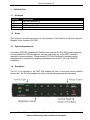
DVI-300 Stand Alone User’s Guide
DOC0499
Applies to:
DVI-300, FW Rev 04.08.00
Document Revision: 01.001
December 16, 2010
SkyTrac Systems Ltd.
#200-170 Rutland Rd North
Kelowna, BC Canada
Tel. +1 (250) 765-2393
Fax +1 (250) 765-3767
Web: www.skytrac.ca
Email: [email protected]
Copyright © 2010 SkyTrac Systems Ltd.
All rights reserved.
SkyTrac Systems Ltd.
Document Revision History
Rev
ECO Page
Description
Date
Author
Approval
01.000 -
Initial Release
Aug 13, 2009
C. Bryson
M. Nordine
01.001
Added ECO
control
Dec. 16, 2010
Y. Liu
T. Ratch
354
Proprietary Notice: The Information contained in this document
is proprietary and confidential to SkyTrac Systems Ltd.
Document Rev. 01.001
DVI-300 Stand Alone User’s Guide
Restricted Proprietary and Confidential Information
Page 2 of 14
SkyTrac Systems Ltd.
Table Of Contents
1
Introduction ...................................................................................................................4
1.1
1.2
1.3
1.4
1.5
2
Acronyms .................................................................................................................4
Scope .......................................................................................................................4
System Requirements ..............................................................................................4
Description ...............................................................................................................4
Features ...................................................................................................................5
General ...........................................................................................................................6
2.1
Setup .......................................................................................................................6
2.1.1
DVI-300 Models ................................................................................................6
2.2
Configuration............................................................................................................6
2.3
Diagnostics ..............................................................................................................6
2.3.1
Power-On Indicator ...........................................................................................6
3
Operation .......................................................................................................................7
3.1
Indicators .................................................................................................................7
3.2
Error Indication.........................................................................................................8
3.3
Dialling .....................................................................................................................8
3.4
Generating DTMF Tones during a Phone Call .........................................................9
3.5
Speed Dial ...............................................................................................................9
3.5.1
Programming Speed Dial Numbers ..................................................................9
3.5.2
Redial................................................................................................................9
3.6
Receiving a Satellite Phone Call ............................................................................10
3.7
Audio Parameters ..................................................................................................10
3.7.1
Call Volume Control ........................................................................................11
3.7.2
Ringer Volume ................................................................................................11
3.7.3
Mic Mute .........................................................................................................11
3.7.4
Side Tone Gain ...............................................................................................11
3.7.5
Ringtone Selection ..........................................................................................11
3.8
Brightness Control .................................................................................................12
3.8.1
Indicator Brightness ........................................................................................12
3.8.2
Backlighting Brightness...................................................................................12
3.9
Text Messages.......................................................................................................12
3.9.1
Programming Text Messages .........................................................................12
3.9.2
Sending Text Message ...................................................................................12
3.10 ISAT Emergency Mode ..........................................................................................13
3.11 Access Control .......................................................................................................13
3.11.1 Enabling PIN ...................................................................................................13
3.11.2 PIN Description ...............................................................................................14
3.11.3 Entering PINS in DVI ......................................................................................14
Document Rev. 01.001
DVI-300 Stand Alone User’s Guide
Restricted Proprietary and Confidential Information
Page 3 of 14
SkyTrac Systems Ltd.
1
1.1
INTRODUCTION
Acronyms
Acronym
STS
DVI
ISAT
CDP
1.2
Description
SkyTrac Systems Ltd.
Dispatch Voice Interface
SkyTrac’s Flight Following Unit.
Cockpit Display Panel
Scope
This document provides instructions on the operation of the features of SkyTrac System’s
Dispatch Voice Interface (DVI-300).
1.3
System Requirements
An installed ISAT-200 (loaded with FirmWare that supports the DVI-300) including antenna
and an installed DVI-300 are required. An open view of the sky by the ISAT antenna is
required for communications. Please contact STS Client Services for software version
requirements for peripherals if updating a peripheral from an ISAT-100 to an ISAT200
installation
1.4
Description
The DVI is an interface to the ISAT that enables the user to send and receive satellite
phone calls. The DVI also enables the user to send pre-programmed text messages.
Document Rev. 01.001
DVI-300 Stand Alone User’s Guide
Restricted Proprietary and Confidential Information
Page 4 of 14
SkyTrac Systems Ltd.
1.5
Features
International number dialling.
Last number redial.
9 Pre-Programmed Speed Dial Numbers.
125 User programmable Speed Dial Numbers.
Volume Control (10 levels).
Side Tone volume control (6 levels)
DTMF Tone dialling for Automated Phone Menus
Up to 10 Pre-Programmed Text Messages.
Indicator to notify user of ISAT Data Delay.
Emergency switch (push button or toggle) to trigger the ISAT emergency mode.
Indicator brightness controls for bright (day) and dim (night) modes.
PIN Number Access Control Feature
Document Rev. 01.001
DVI-300 Stand Alone User’s Guide
Restricted Proprietary and Confidential Information
Page 5 of 14
SkyTrac Systems Ltd.
2
GENERAL
2.1
Setup
The DVI-300 communicates with the ISAT through a RS485 connection. Refer to the
document DVI-300 System Operation and Installation Manual for details on the installation
of DVI-300. The DVI-300 does not process or provide audio signals. Audio signals are
provided directly from the ISAT to aircraft audio systems. Refer to the ISAT System
Installation Manual for details on how to setup the base audio levels during installation.
2.1.1 DVI-300 Models
Type
Part Numbers
Description
Green backlighting with locking toggle
emergency switch
Compatibility *
101-200-01,
101-200-02
DVI-300C
105-300-01
DVI-300A
105-300-02
NVIS A backlighting with locking toggle
emergency switch
101-200-01,
101-200-02
DVI-300CP
105-300-03
Green backlighting with push button
emergency switch
101-200-01,
101-200-02
DVI-300AP
105-300-04
NVIS A backlighting with push button
emergency switch
101-200-01,
101-200-02
2.2
Configuration
The DVI-300 is connected using the RS485 link and functions as an intelligent interface with
calling and messaging features and support for the CDU-300 when combined with a CDP300.
2.2.1.1.1.1.1.1
2.3
Diagnostics
2.3.1 Power-On Indicator
When the DVI-300 powers up, the three indicators briefly illuminate once to indicate start-up
and initialization (unless in programming mode).
Document Rev. 01.001
DVI-300 Stand Alone User’s Guide
Restricted Proprietary and Confidential Information
Page 6 of 14
SkyTrac Systems Ltd.
3
OPERATION
Caution: While in a voice call the ISAT is unable to send position reports. All position
reports are queued and delivered when the call is finished. Users should limit the
length of the voice call in order to allow position reports to be transmitted in a timely
manner.
3.1
Indicators
The DVI-300 has three Indicators that provide visual feedback to the users during its
operation. The following table summarizes the behaviour of the indicators for different
actions. The ‘Msg In’ indicator is used in the DVI-300 standalone mode to indicate
communication failure with the ISAT.
Indicator
Activity
Activity
Activity
Action
Indicate a key press
Operation Unsuccessful, Cancelled
by user, or not permitted/ error
ISAT Emergency
Behaviour
Blinks once
Blinks four times rapidly
stays on solid after blinking all
indicators in rotation (DVI standalone
operation only)
Activity,
Activate the ISAT Emergency mode,
When ISAT emergency is activated
Data delay, or if the user attempts to use the DVI all indicators blink in rotation briefly,
Msg In
keypad when the Emergency mode is (DVI standalone mode only)
active
Activity
Call placed/ Call Answered
Turns ON solid until the call is
terminated
Activity
Brightness increased/decreased
Blinks twice slowly
Activity
Volume increased/decreased
Blinks twice slowly
Activity
Text message sent
Blinks twice slowly
Activity
Waiting for PIN number entry
Blinks eight times slowly
Data delay ISAT – Satellite communication
Turns ON solid until the
failure – or position reports queued
communication is restored or queued
reports have been sent
Data delay RS485 communication link failure or
Data delay blinks four times (for 3
and Msg In if the user attempts to use the keypad times in a row) and then Msg-In goes
while RS485 communication is not
on solid
available
Msg In
New Email - Not applicable to DVI
standalone operation
Document Rev. 01.001
DVI-300 Stand Alone User’s Guide
Restricted Proprietary and Confidential Information
Page 7 of 14
SkyTrac Systems Ltd.
3.2
Error Indication
If an error occurs in the operation of the DVI-300, the Activity indicator will rapidly flash four
times to indicate an error and clear all key presses.
For example, if the user attempts to dial * 8 SEND (Fctn 8 SEND) the DVI-300 Activity
indicator will flash four times and clear its memory of the keys pressed, thus allowing the
user to start again fresh.
Note: There is a 60 second timeout when pressing keys. If the timeout elapses between key
presses, the Activity indicator flashes four times, indicating an error and the DVI-300 resets
the keypad as if there have been no key presses.
3.3
Dialling
To dial a phone number, simply dial the desired number using the keypad and press the
Send Key.
The Activity indicator will flash once to indicate when each digit of a number has been
entered. Repeat this process until all the numbers have been entered. When finished, press
the Send key to initiate the call. If a mistake has been made press # or * once to cancel
previous entries and start fresh.
A long distance number must be dialled regardless of the location of the aircraft.
To place a call, dial an international number: International Direct Dialling (IDD) prefix of the
country you are calling from (00 for Iridium) then the destination country code (1 for Canada
and the US), followed by the area code and local number.
For example, to call SkyTrac Systems office, dial: 00 1 250 765 2393
Once a call has been initiated, the Activity indicator will stay on solid indicating the ISAT is
initiating the call. It may take a moment for the ISAT to initiate the call if it is already busy
communicating with the Iridium network. To hang-up simply press the Send key again.
Once the call is initiated by the ISAT, the user will hear a periodic beep. If the call fails, the
user will hear beeps to indicate the signal was lost. If the signal is lost, the call will end and
the Activity indicator will go out.
The user will hear a normal telephone ring when the call connects.
If you make a mistake dialling, pressing * or # once to clear the entries and you can begin
dialling again.
Document Rev. 01.001
DVI-300 Stand Alone User’s Guide
Restricted Proprietary and Confidential Information
Page 8 of 14
SkyTrac Systems Ltd.
3.4
Generating DTMF Tones during a Phone Call
The DVI-300 can generate DTMF tones, enabling the user to access automated voice
menus. They will hear the DTMF tones over the headset.
DTMF Tones can only be generated once a phone call is already in progress. In order to
generate a DTMF tone, press the desired key for each tone desired. For example to send
the tones for numbers 5768# to an automated menu, press 5768# in sequence when the
call is in progress. Allow the Activity indicator to flash twice between successive digits.
3.5
Speed Dial
The user has the option to program up to 9 Speed Dial numbers (corresponding to keypad
numbers 1 through to 9) via the key pad and up to 125 via the SkyWeb application (see the
user’s SkyWeb Program Manager or their designate to get these entered).
Note: Position 0 is used for redial purposes and cannot be programmed as a speed dial.
Simply press the one digit speed dial number and press the Send key to dial the preprogrammed number. If a mistake has been made press # or * once to cancel. If more than
one number is entered the DVI-300 will treat the number as a regular phone number dialling
sequence and attempt to dial the number when the Send key is pressed.
Once the call is initiated the DVI-300 operates the same as it does for a manual dialled call.
3.5.1 Programming Speed Dial Numbers
Speed dial numbers can be assigned using the DVI-300 keypad. To assign a phone number
to a key (for keypad 1 through to 9), press * 2 (FCTN 2). Then enter the speed dial phone
number to be assigned. Once the phone number is entered, press the * (FCTN) key again
followed by the number key to which the speed dial number is to be assigned.
The Activity indicator will flash once for each of the key presses except for last key press.
The Activity indicator will flash twice at the last key press to indicate a successful
programming assignment.
For example to assign the phone number 001 300 765 2393 to speed dial key 3, press
*20012507652393*3
3.5.2 Redial
Pressing the ‘0’ key followed by the Send key will place a call to the last number dialled.
If there is no last number stored, the DVI-300 will flash Activity indicator four times indicating
an error. Last number dialled is erased when the DVI restarts.
Document Rev. 01.001
DVI-300 Stand Alone User’s Guide
Restricted Proprietary and Confidential Information
Page 9 of 14
SkyTrac Systems Ltd.
3.6
Receiving a Satellite Phone Call
In order to dial the ISAT from the ground, the user must dial an international number. The
country code for the Iridium Satellite network is 8816 or 8817. To dial an international
number, dial the International Direct Dialling (IDD) prefix of the country you are calling from
(011 for Canada and the US) then the destination country code (8816), followed by the
ISAT’s number.
Example: 011 8816 3101 0616
When a call comes in to the ISAT, the DVI Activity indicator will illuminate and an audible
ring will be heard on the headset. To answer the call, press the Send key. When finished,
press the Send key again to hang up. If the ground user hangs up, it may take the Iridium
system a few moments to detect the hang up before the ISAT will automatically end the call.
The Activity indicator will go out when the ISAT hangs up the call.
It may take several attempts to connect to the Iridium network when dialling the ISAT from
the ground. If the first attempt fails, try again.
3.7
Audio Parameters
The complete list of settable ISAT-200 audio parameters is:
1.
2.
3.
4.
5.
6.
7.
8.
Mic DC bias (completed during install)
Mic Input Level (completed during install)
Mic Volume (changed on the ISAT itself)
Call Volume (10 levels)
Ringer Volume (10 levels)
Mic Mute (On/Off)
Side Tone Volume (6 levels)
Ringtone Selection (6 tones available)
Two of these parameters must be set to properly install the ISAT-200. They are Mic DC
bias and Mic input level. Once set, these parameters will not typically be changed.
See the ISAT-200 Installation guide for further details.
The other parameters, Call Volume, Ringer Volume, Mic Mute, Side Tone Gain, and
Ringtone selection can be altered by the user in the course of normal use.
The following section explains how to change these settings on the DVI-300 itself. See the
ISAT-200 User’s Manual for instructions on setting these parameters on the ISAT itself.
Note: These parameters retain the last value set in the course of normal use.
Document Rev. 01.001
DVI-300 Stand Alone User’s Guide
Restricted Proprietary and Confidential Information
Page 10 of 14
SkyTrac Systems Ltd.
3.7.1 Call Volume Control
The DVI-300 allows the user to change the volume only when a call is in progress. The DVI300 has ten volume settings. To change the volume during a call simply press * 6 (FCTN 6)
to increase the volume, or * # (FCTN #) to lower the volume.
Note: It may take up to 30 seconds for the volume to adjust
3.7.2 Ringer Volume
The ringer volume also has ten settings and can be adjusted when the user is not on an
active call. The user must use the same key presses as those used for call volume.
3.7.3 Mic Mute
The microphone can be muted only when a call is in progress. Selecting * 5 (FCTN 5) will
toggle between muting the call and reverting back to normal.
3.7.4 Side Tone Gain
The side tone gain has 6 levels of adjustment. Selecting *4 (FCTN 4) will increase the level
and * 0 (FCTN 0) will reduce it.
3.7.5
Ringtone Selection
Connect your headset to the ISAT. As each choice is selected then the associated Ring
Tone will sound for one second in the headset.
If nothing is heard after toggling through a selection, increase the Ringtone Volume and
then try again.
If no setting results in an audible ring tone, please double check the wiring and ensure the
procedures in the ISAT Installation Manual have been followed completely.
Parameter
Call Volume (on active call)
Ringer Volume (no active call)
Mic Mute (on active call)
Side Tone Gain
Ringtone Selection (no active call)
Method
FCTN 6 - Increase
FCTN # - decrease
As above
FCTN 5 - Toggles between mute and un-mute
FCTN 4 - Increase
FCTN 0 - Decrease
FCTN 5 + Ringtone Number (1-6)
Document Rev. 01.001
DVI-300 Stand Alone User’s Guide
Restricted Proprietary and Confidential Information
Page 11 of 14
SkyTrac Systems Ltd.
3.8
Brightness Control
3.8.1 Indicator Brightness
The DVI-300 indicators operate in two brightness modes - bright (day) mode and dim (night)
mode. The DVI-300 can be wired to the aircraft dimmer bus (see note below) so that it can
switch seamlessly between these modes based on the aircraft cabin lighting or the aircraft
dimmer bus. When the dimmer bus is off, the DVI-300 is in bright (day) mode.
The brightness level of the indicators can also be changed manually at anytime. To change
the brightness at any time manually, simply press * 1 (Fctn 1) to increase the brightness, or
* 7 (Fctn 7) to decrease the brightness.
Refer to DVI-300 Wiring Installation Diagram and DVI-300 System Operation and
Installation Manual for details regarding connecting the DVI-300 to the aircraft dimmer bus.
Note: Currently SkyTrac Client Services ([email protected]) will need to be
contacted to configure the dimmer bus on the DVI-300 standalone.
3.8.2 Backlighting Brightness
Efficient and long lasting LED illumination enables the backlighting to be on all the time.
When the DVI-300 is connected to the aircraft dimmer bus, the DVI-300 backlighting follows
the aircraft dimmer bus voltage. If the aircraft dimmer bus is not connected to the DVI-300,
or the aircraft dimmer bus voltage is off (for day use), the backlighting is on at full
brightness. This ensures that regardless of the ambient lighting conditions, the keys will
remain visible. Note that the Indicator brightness is separately controlled.
3.9
Text Messages
3.9.1 Programming Text Messages
The user has the option of pre-programming up to 10 DVI text messages (0 through to 9) to
a text message list. Text messages can be programmed using FlightTrac Suite. Refer to the
FlightTrac User Manual to learn how to program text messages
3.9.2 Sending Text Message
To send a Text Message, press # and the number of the desired text message. Then press
the Send key to send the message – the Activity indicator will flash twice to indicate that the
message has been sent. If a mistake has been made press # or * once to cancel. If more
than one number is entered after the # key, the Activity indicator will flash four times to
indicate an error and clear previous entries.
Document Rev. 01.001
DVI-300 Stand Alone User’s Guide
Restricted Proprietary and Confidential Information
Page 12 of 14
SkyTrac Systems Ltd.
3.10 ISAT Emergency Mode
The ISAT Emergency mode (ISAT EMERG) is activated or cancelled (to return to Normal
“NORM” mode) via a locking toggle switch, or pushbutton switch on the DVI-300 front panel
as described below.
DVI-300 – switch type
Activate ISAT Emergency Cancel ISAT Emergency
Locking toggle switch Place the locking toggle switch into Place the locking toggle switch into
(applies
300C)
to
DVI-300A,
Pushbutton
DVI-
the “ISAT EMERG” position (up)
the “NORM” position (down)
switch Press and hold the pushbutton for Press and hold the pushbutton for a
(applicable to DVI-300AP, DVI300CP only)
a minimum of 3 seconds or longer
(while operating in Normal mode)
minimum of 3 seconds or longer
(when operating in Emergency mode)
Both Toggle switch and Push button switch models will blink the 3 DVI indicators in rotation
then turn the activity indicator on Solid when the ISAT Emergency mode is activated and the
DVI is operating as a standalone device.
.
During ISAT emergency mode operation, DVI key presses are ignored, and cause the 3
indicators to blink in rotation.
The ISAT does not allow voice calls or text messages to be sent while in ISAT emergency
mode. If the user is in a voice call when ISAT Emergency is triggered, the ISAT will end the
voice call in order to send emergency position reports.
Switching the ISAT back to Normal mode (Norm) ends the emergency condition. The DVI
activity indicator blinks twice to confirm when the ISAT has returned to Normal Mode.
3.11 Access Control
3.11.1 Enabling PIN
To activate the PIN feature in your DVI-300, please contact Skytrac Systems.
If the PIN feature is not activated for your installation then there are no restrictions to calling
or messaging and all users have full access to Sat Phone calling, and DVI text messaging.
Note: The following description is valid only if PINS are activated in the DVI-300
The DVI-300 supports restricted access to the calling and text messaging features of the
ISAT by the use of a PIN number. PIN numbers could be used for the following purposes:
1. To prevent unauthorized access of calling and text messaging
2. To determine or track the call usage (duration) of each DVI-300 user.
Document Rev. 01.001
DVI-300 Stand Alone User’s Guide
Restricted Proprietary and Confidential Information
Page 13 of 14
SkyTrac Systems Ltd.
3.11.2 PIN Description
The DVI-300 supports a maximum of 400 distinct PINS – i.e. the DVI-300 will be able to
identify up to a maximum of 400 distinct users.
The PIN length can be 4, 5 or 6. This length applies to all the PINS used in the DVI-300.
For each PIN, an access level can be configured to
•
•
•
Enable/Disable incoming calls
Enable/Disable outgoing calls
Enable/Disable outgoing text messages
When the PIN feature is activated, a default access level must be set for the DVI-300. This
default access level will be used if no PIN is entered in to the DVI-300 or when an invalid
PIN is entered to the DVI-300. For example, if the default access level is set to disable
outgoing calls and messaging, then a user cannot make an outgoing call unless they enter a
PIN with an access level to make outgoing calls.
3.11.3 Entering PINS in DVI
When the DVI-300 starts-up, it will prompt the user to enter a PIN by blinking the activity
light 8 times. If a valid PIN is entered then the activity light will blink twice indicating a valid
PIN. If an invalid PIN is entered, then the activity light will flash four times rapidly indicating
an error.
If a PIN is not entered within the 8th flash, the DVI-300 will use the default PIN. To enter a
PIN after start-up, press *8 followed by the PIN and then press Send. If a valid PIN is
entered then the activity light will blink twice. If an invalid PIN is entered, then the activity
light will flash four times.
A PIN has to be entered every time the DVI-300 powers-up. At any time, the DVI-300 can
be put to use the default access level by entering *8 followed by 0 and then Send. The
activity light will blink four times indicating that the default access level is used.
Document Rev. 01.001
DVI-300 Stand Alone User’s Guide
Restricted Proprietary and Confidential Information
Page 14 of 14