1
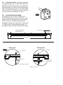
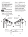
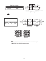
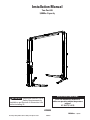
Installation Manual
Two-Post Lift
9,000lbs. Capacity
OPERATING CONDITIONS
)-0/24!.4 Reference ANSI/ALI ALIS,
Safety Requirements for
Installation and Service of Automotive Lifts
before installing lift.
Lift is not intended for outdoor use
and has an operating ambient temperature
range of
41°-104°F (5°-40°C)
LP50029
IN50029Rev. © January 2013 by Vehicle Service Group. All rights reserved.
CO8325.3
1/8/2013
F
E
G
H
A
I
B
C
Fig. 1a
D
28" MIN
ARM REACH
41 1/2" MAX
ARM REACH
J
K
30 1/2" MIN
ARM REACH
Fig. 1b
44 3/4"MAX
ARM REACH
L
L
2
1. Lift Location: Use architects plan when available to locate lift. Fig. 1a & Fig. 1b shows dimensions of a
typical bay layout.
WARNING
DO NOT install this lift in a pit or depression due to fire or explosion risks.
A
B
C
D
E
F
G
H
I
J
K
L
POWER UNIT HEIGHT
LIFTING HEIGHT W/ 5" EXTENSION
MIN. LIFT HEIGHT
MIN. LIFT HEIGHT W/ 1 3/4" ADAPTER
72-1/2"
76-5/8" W/ 68" STROKE
3-5/8"
5-3/8"
MIN. LIFT HEIGHT W/ 5" ADAPTER
OVERALL FLOOR WIDTH
INSIDE COLUMNS
8 5/8"
132"
109"
WIDTH BETWEEN CARRIAGES
HEIGHT OVERALL
MIN. FLOOR CEILING HEIGHT
FLOOR TO OVERHEAD SWITCH
DRIVE THRU CLEARANCE
MINIMUM TO NEAREST OBSTRUCTION
MINIMUM TO NEAREST OBSTRUCTION
MINIMUM TO NEAREST OBSTRUCTION
107"
142"
144"
137-5/8"
99"
132"
156"
72"
NOTES:
1.) ALL HEIGHT DIMENSIONS ARE WITHOUT LEVELING SHIMS.
2.) STANDARD HEIGHT LIFT SHOWN.
3.) “ ANCHORING SYSTEM TESTED TO ANSI/ALI ALCTV 2006.
LIFT CAPACITY
LIFTING SPEED (RISE TIME)
9,000 LBS.
APPROXIMATELY 45 SECONDS UNLOADED
APPROXIMATELY 51 SECONDS AT RATED CAPACITY
SINGLE PHASE 208-240V 50-60Hz 18-23 AMPS
MOTOR RATING OPTIONS
3 PHASE 208-230/460V 50-60Hz 17/8.5-14/8 AMPS
WEIGHT
1500 LBS
MECHANICAL SAFETY LOCKS AUTOMATIC ALL POSITIONS
MECHANICAL SAFETY RELEASE MANUAL ALL BOTH COLUMNS
SWING ARM LOCKS
AUTOMATIC LOCKING ABOVE 2 1/2"
HYDRAULIC SAFETY SYSTEM
AUTOMATIC ALL POSITIONS
CYLINDERS
TWO, ONE PER COLUMN
CARRIAGE BEARINGS
EIGHT PER CARRIAGE, UHMW
SYNCHRONIZATION
EQUALIZATION CABLES
MIN. BAY SIZE
12' X 24' VERIFY WITH SITE PLAN & SERVICE VEHICLES
3
2. Power Unit Tee Cover Plate: While power unit
column is laying on the ground, install the cover plate
using (2) M4x6 Lg. PHMS Fig. 2.
M4x6 Lg. PHMS
3. Hoses: Clean adapters and hose. Inspect all
threads for damage and hose ends to be sure they are
crimped.
Flared Fittings Tightening Procedure
1. Screw the fittings together finger tight. Then, using
the proper size wrench, rotate the fitting 2-1/2 hex
flats.
Fig. 2
IMPORTANT Flare seat MUST NOT rotate when
tightening. Only the nut should turn.
2. Back the fitting off one full turn.
3. Again tighten the fittings finger tight; then using a
wrench, rotate the fitting 2-1/2 hex flats. This will
complete the tightening procedure and develop a
pressure tight seal.
4. Power Unit Tee: With the column still laying on the
ground push the lift carriage as high as possible to
install the power unit tee. Once carriage is rasied,
install the power unit tee and hoses to the column Fig.
3.
CAUTION Overtightening will damage fitting
resulting in fluid leakage.
CAUTION Overtightening will damage fitting
resulting in fluid leakage.
CAUTION Over tightening locknut may tear O-ring
or distort threads in pump manifold outlet.
Hydraulic Hose
Fig. 3
Power Unit Tee
Carriage
4
5. Column Extensions: Install the column extensions
using (2) 1/2”-13NC x 1 1/4” Carriage HHCS and Nylon
Locknuts, Fig. 4.
7. Latch Cable Guides: Install the latch cable conduit
guide brackets to column extensions with (1) 1/4”20NC x 1” HHCS and 1/4”-20NC Flanged Locknuts,
HHCS should go through hole nearest the edge as
shown, Fig. 6.
8. Lift Setting: Position columns in bay using
dimensions shown in Fig. 1a & Fig. 1b. Place column
with power unit mounting bracket on vehicle
passenger side of lift. Both column base plate backs
must be square on center line of lift. Notches are cut
into each base plate to indicate center line of lift. Use
appropriate equipment to raise carriage to first latch
position. Be sure locking latch is securely engaged.
Fig. 4
1/2”-13NC Nylon Locknut
& 1/2” Flat Washer
Fig. 6
1/2”-13NC x 1-1/4” HHCS &
1/2” Flat Washer
6. Reinforcement Bar: Install the reinforcement bar to
the column and column extension using (2) 1/2”-13NC
x 1-1/4” HHCS, (4) 1/2” Flat Washer, and (2) 1/2”-13NC
Nylon Locknut Fig. 5.
9. Cylinder Fitting/Flow Valve: Push the carriage to
first lock and then install the flow valve and 90° elbow
to the cylinder through the small opening on the bottom of the column. Fig 7.
Fig. 5
CAUTION Overtightening will damage fitting
resulting in fluid leakage.
1/2”-13NC x 1-1/4” HHCS
& 1/2” Flat Washer
1/2”-13NC Nylon Locknut
& 1/2” Flat Washer
Fig. 7
5
Flow Valve Body
90° Elbow
10a. Overhead Assembly: Fig. 9: Adjust overhead
to appropriate dimension. Install (4) 3/8”-16NC x 3/4”
HHCS & 3/8”-16NC Flanged Locknuts, do not tighten.
Slide Switch Box over switch bar ensuring knock out
holes face the power unit column. Use (2) 1/4”-20NC
x 3/4” lg. HHCS, 1/4” Flat Washer, and 1/4”-20NC Nuts
to mount switch box to overhead, see Fig. 8.
Fig. 8
10b. Continued Overhead Assembly:
For single phase lifts: Insert 1/4”-20NC x 2 3/4”
HHCS through pivot hole in end of switch bar. Insert
opposite end of bar through slot in switch mounting
bracket. Then secure HHCS and Switch Bar to
overhead as shown, Fig. 9, using (2) 3/4” spacers and
1/4”-20NC Locknut. Tighten Hex bolt leaving 1/16”
gap between the spacer and the overhead assembly.
7 3/4" Standard
M10-1.5 x 20mm HHCS
& Flanged Locknut
108" Standard
Open Bar Side
Switch Box Side
Fig. 9
1/4" Lock Nut
1/4" Lock Nut
2 Spacers
1/4" Flat
Washer
1/4"-20NC x 2 3/4" HHCS
1/4"-20NC x 3/4" HHCS
6
For three phase lifts: Remove Limit Switch cover,
Fig. 10. Insert Actuator end of Switch Bar into slot
located inside Limit Switch, Fig. 10. A small amount of
silicone sealant on the lower part of the actuator will
help hold it in place. Insert 1/4”-20NC x 2 3/4” HHCS
through pivot hole in end of Switch Bar. Then secure
HHCS and Switch Bar to overhead as shown, using
(2) 3/4” spacers and 1/4”-20NC Locknut. Tighten Hex
bolt leaving 1/16” gap between the spacer and the
overhead assembly, Fig. 9. Replace limit switch cover.
Use M10-1.5 x 20mm
HHCS and Locknuts
Fig. 11
Fig. 10
12. Power Unit: First install a star washer onto all
of the (4) 5/16”-18NC x 1-1/2” HHCS. This is very
important for grounding. Put the (4) 5/16”-18NC x
1-1/2” HHCS thru holes in power unit bracket, Fig.
12. Mount unit with motor up to column bracket and
install (4) 5/16” star washers and 5/16” Nuts. Install
and hand tighten fitting to pump until O-ring is seated.
Continue to tighten the locknut until the nut and
washer bottom out against the pump manifold.
Remove Screws
And Cover
Place Actuator Here.
A Small Amount Of Silicone Sealant
On The Lower Part Of The Actuator
Will Help Hold It In Place.
Cradle Bar
On Actuator
NOTE: You may still be able to rotate the fitting. This
is acceptable unless there is seepage at the O-ring. If
so, slightly tighten the locknut.
Actuator
Use (4)5/16"-18NC
x1-1/2" lg. HHCS
and Nuts
Fig. 12
11. Overhead Installation: Install overhead assembly
to Mounting Bracket with (2) M10-1.5 x 20mm HHCS,
and (2) M10-1.5 Flanged Locknut Fig. 11. Tighten bolts
at center of overhead assembly.
On all four bolts, place
(2) 5/16" Star Washers
Fill Breather Cap
7
13. Adapter & Hose Installation (see Fig. 14)
1. Connect the free end of the second shortest hose
Pc. (2), from paragraph 3, to the power unit side
cylinder Pc. (1). Run hose through channel inside
column.
3. Run the free end of the longest hose Pc. (3), from
paragraph 3, through hose clamps Pc.(9), and
channel. Then connect it to the slave side cylinder.
4. Take the end of the remaining hose Pc. (4) out
of the column and connect it to the fitting on the
power unit Fig. 13.
Cylinder Bleeders
6
Hose runs down
approach side to
cylinder on left column.
3
NOTE: Overhead hose goes over top end of overhead
assembly, Fig. 14 & Fig. 18a & Fig. 18b.
4
5
FRONT
2
1
Fig. 14
7
Fitting
8
ITEM
1
2
3
4
5
6
Power Unit
Hose
Fig. 13
7
8
8
QTY.
2
1
1
1
1
2
2
2
2
2
DESCRIPTION
Hydraulic Cylinder
Cylinder Hose
Slave Side Hose
Power Unit Hose
3/8” Branch Tee
Hose Clips
M10-1.5 x 20mm HHCS
M10-1.5 Flanged Locknuts
90° Fitting
Flow Control Valve
14. Equalizing Cables
A) Refer to Fig. 16 for the general cable arrangement.
B) First, run a cable end up through the small hole in
the tie-off plate. Fig. 17.
C) Push the cable up until the stud is out of the
carriage top opening.
D) Run a nylon insert locknut onto the cable stud so
1/2” (13mm) of the stud extends out of the locknut.
E) Pull the cable back down, Fig. 17.
F) Run cable around the lower sheave, then up and
out of the top of the column.
G) Run cable around overhead sheave and across
and down to the opposite carriage. Install sheave
cover, Fig. 15.
H) Fasten the cable end to the carriage upper tie-off
bracket, Fig. 17. Tighten the locknut enough to
I) Adjust the tension of both cables during the final
adjustments in Paragraph 24.
Upper Sheaves
2nd Cable
Fig. 16
1st Cable
Lower Sheaves
Uper Cable Tie Off
& 5/8" Nylon Insert
Locknut
Fig. 15
Sheave Cover
Fig. 17
Lower Cable Tie Off
& 5/8" Nylon Insert
Locknut
9
F) Bring the cable down inside the left column and
feed the end of the cable through the lower latch
cable sheave slot so that the cable is now back
outside the column, Fig. 21.
G) Route cable under the bottom side of the latch
cable sheave, Fig. 21.
H) At this point you MUST install the latch handle,
jam nut, and right column latch cover Fig. 19 & Fig.
22. Install latch handle ball, Fig. 22.
I) Insert cable in cable clamp along one side, loop
around shoulder screw and back down, inserting
cable along other side of cable clamp, Fig. 21.
Place top back on clamp, barely tightening.
J) Next, pull the control plate down, Fig. 20 & Fig. 21,
to eliminate any clearance between the control
plate slot and the latch dog pin, Fig. 20.
K) Using Pliers, pull cable tight and secure the clamp
close to the shoulder screw. Tighten clamp.
15. Locking Latch Cable
A) Slip loop end of cable over end of shoulder screw
on right side latch control plate, Fig. 19.
B) Feed the other end of the cable through the latch
cable sheave slot making sure that the cable is
running under the bottom side of the latch cable
sheave and inside the right column, Fig. 19.
C) Attach latch cable conduit guide brackets to
overhead as shown, Fig. 18a & Fig. 18b. Always
use the holes on the approach side of the lift.
HHCS should be in hole nearest the center of the
overhead, Fig. 18b.
D) Route cable up inside column and through the
latch cable guide, Fig. 18a & Fig. 20.
IMPORTANT Using wire ties provided, tie off
hydraulic hose snug to cylinders to keep hose
away from equalizing cable, Fig. 14.
E) Continue routing cable to the left column latch
cable guide, Fig. 18a & Fig. 20, routing the cable
through the left column latch cable guide, Fig. 18a.
Cable Guide
runs UNDER
hydraulic hose
Cable Guide
does not cross
hydraulic hose
M10-1.5 x 20mm HHCS
and Flanged Locknut
M10-1.5 x 20mm HHCS
and Flanged Locknut
1/4"-20NC x 1" HHCS
and Flanged Locknut
1/4"-20NC x 1" HHCS
and Flanged Locknut
Fig. 18a
Attach Hose Clamps Here
Attach Latch Cable Conduit
Guide Bracket Here. Always
use two holes on approach
side of extension to attach bracket.
APPROACH
Always put HHCS through hole
closest to center of overhead.
Fig. 18b
10
Latch Cable Sheave
(2) 3/8" Retaining Rings
Fig. 19
Shoulder Bolt
Install Latch Handle using a 3/8"
hex jam nut to lock in place. Then
install flat washers and slot cover.
,ATCH#ABLE'UIDE
,ATCH#ABLE
Fig. 20
.OTICETHECLEARANCE
REMOVEDBETWEEN
#ONTROL0LATE3LOT
AND,ATCH$OG0IN
(3) 3/8” Flat Washers
Slot Cover
2IGHT#OLUMN
Shoulder Bolt
Feed cable up through Cable
Clamp, loop over end of
shoulder bolt and feed back
down through Cable Clamp.
Cable Clamp
Latch Cable Sheave
Fig. 21
(2) 3/8" Retaining
Rings
5/16-18NC x 3/8" lg. PHMS
Latch handle MUST be
positioned at the top of
the latch control cover.
11
Ball Handle
Fig. 22
Recheck columns for plumb. Tighten anchor bolts to
an installation torque of 110 ft-lbs. Shim thickness
MUST NOT exceed 1/2” when using the 5-1/2” long
anchors provided with the lift, Fig. 23. Adjust the
column extensions plumb.
16. Concrete and Anchoring:
Drill (10) 3/4” dia. holes in concrete floor using holes
in column base plate as a guide. See Fig. 24 for hole
depth, hole spacing, and edge distance requirements.
CAUTION DO NOT install on asphalt or other
similar unstable surfaces. Columns are supported
only by anchors in floor.
If anchors do not tighten to 110 ft-lbs. installation
torque, replace concrete under each column base
with a 4’ x 4’ x 6” thick 3000 PSI minimum concrete
pad keyed under and flush with the top of existing
floor. Let concrete cure before installing lifts and
anchors.
IMPORTANT Using the horse shoe shims provided,
shim each column base until each column is plumb.
Anchor
Nut
Flat
Washer
Fig. 23
Shims
(1/2" Max.)
NOTE: Use rectangular
shims at inside edge of
baseplate. Use
constructions adhesive
or silicon cement to
hold shim in place.
INSURE shims are held
tightly between base
plate and floor after
torquing anchors.
NOTE: If more than 2 horse shoe shims are used at any of
the column anchor bolts, pack non-shrink grout under the
unsupported area of the column base. Insure shims are held
tightly between the baseplate and floor after torquing anchors.
12
Fig. 24
Drill holes using 3/4” carbide tipped masonry drill
bit per ANSI B212.15-1994
(R2000)
Clean hole.
Run nut down just
below impact section
of bolt. Drive anchor
into hole until nut and washer
contact base.
Tighten nut with
Torque wrench to 110
ft.-lbs.
CONCRETE AND ANCHORING REQUIREMENTS
STANDARD
ANSI/ALI ALCTV
IBC 2006, 2009, 2012
Minimum Floor Thickness 4-1/4 INCHES
5 INCHES
Anchor
Hilti HIT-HY 150
Hilti Kwik Bolt III
MAX-SD Adhesive; 3/4" x 7"
Hilti HIT-HY 150
MAX Adhesive;
HILTI HIT-RE 500SD Adhesive
Minimum Concrete
Strength
Hilti Kwik Bolt III
3/4" x 5-1/2"
Anchors supplied
with the lift.*
3000 PSI
6 INCHES
3000 PSI
3000 PSI
Minimum Anchor Embed- 3-1/4 INCHES
ment
3-1/2 INCHES
3-3/4 INCHES
Minimum Distance to
Concrete Edge, Crack,
Expansion Joint, Abandanoned Anchor Hole
5-1/4 INCHES
3-1/4 INCHES
4-1/2 INCHES
*The supplied concrete fasteners meet the criteria of the American National Standard
“Automotive Lifts - Safety Requirements for Construction, Testing, and Validation”
ANSI/ALI ALCTV-2011, and the lift owner is responsible for all charges related to any
additional anchoring requirements as specified by local codes.
Contact customer service for further information at: 800.640.5438
13
17. Electrical: Have a certified electrician run
appropriate power supply to motor, Fig. 20 & 21.
Size wire for 20 amp circuit. See Motor Operating
Data Table.
Service From
Master Control Panel
(3 Wire) Into Junction
Box On Power Unit
Attach With Strain
Relief Provided
CAUTION Never operate the motor on line voltage
less than 208V. Motor damage may occur.
IMPORTANT: Use separate circuit for each power
unit. Protect each circuit with time delay fuse or
circuit breaker. For single phase 208-230V, use 20
amp fuse. Three phase 208-240V, use 20 amp fuse.
For three phase 400V and above, use 10 amp fuse. For
three phase 380V use 16 amp fuse. For wiring see Fig.
20 & Fig. 21. All wiring must comply with NEC and all
local electrical codes.
Fig. 25a
Note: 60Hz. single phase motor CAN NOT be run on
50Hz. line without a physical change in the motor.
NOTE: Assure cord used for connection
between the overhead switch and power
unit is of the type specified in:
Attach black wire
to one motor wire.
From Master
Control Panel.
UL201, Sections 10.1.1.3 & 10.1.1.4
(Example: SO, G, STO) Size for 25 amp
circuit. See UL 201, Section 15 for proper
wiring requirements for this connection.
Attach white
wire to
one motor wire.
Attach ground
wire here.
Attach ground wire to
screws provided.
14
Disconnect Overhead
(If Required) Limit Switch
Single Phase Power Unit
Black
Black
MOTOR OPERATING DATA TABLE - SINGLE PHASE
LINE VOLTAGE
208-230V 50Hz.
RUNNING MOTOR VOLTAGE RANGE
197-253V
208-230V 60Hz.
197-253V
230V
60Hz
1Ø
Up
Switch
Green
Black
M
White
White
Note: 60Hz. Single phase motor CAN NOT be run on 50Hz.
line without a physical change in the motor.
Fig. 25b
Three Phase Power Unit
MOTOR OPERATING DATA - THREE PHASE
LINE VOLTAGE
208 - 230 Volts 60 HZ
460 Volts
60 HZ
3 Phase
Supply
RUNNING MOTOR VOLTAGE RANGE
197
253 Volts
414
506 Volts
L1
1
2
1
2
L2
3
4
5
6
L3
5
6
7
8
PE
OVERHEAD SWITCH
(WHERE APPLICABLE)
L3
T3
T9
T6
L3
T3
T9
T6
L2
T2
T8
T5
L2
T2
T8
T5
L1
T1
T7
T4
L1
T1
T7
T4
208-240V
50/60Hz. 3Ø
DRUM
SWITCH
440-480V 50/60 Hz. 3Ø
400V 50 Hz. 3Ø
NOTES:
1. Unit not suitable for use in unusual conditions. Contact VSG for moisture and dust environment duty unit.
2. Verify Coil Rating Matches Supply Voltage
3. Motor rotation is counter clockwisewhen viewed from top of motor.
15
MOTOR
18. Oil Filling & Bleeding: Use Dexron III ATF, or
Hydraulic Fluid that meets ISO 32 specifications.
Remove fill-breather cap, Fig. 12. Pour in (8) quarts
of fluid. Start unit, raise lift about 2 ft. Open cylinder
bleeders approximately 2 turns, Fig. 14.
CAUTION
Close bleeders when fluid streams. Torque values
for the bleeders are 15 ft. lb. minimum and 20 ft lb.
maximum. Fully lower lift. Add more fluid until it
reaches the MIN______ mark on the tank. Replace
fill-breather cap.
Installation
Pinch Point
Keep Hands
Above Groove
CAUTION If fill-breather cap is lost or broken, order
replacement. Reservoir must be vented.
19. Overhead switch: Check overhead switch
assembly to assure that switch bar is depressing
switch plunger sufficiently to actuate the switch. The
overhead switch is wired normally open, see Fig. 25a
& Fig. 25b. Lift will not operate until weight of switch
bar is depressing switch plunger. Verify that Power
Unit stops working when switch bar is raised, and restarts when the bar is released.
NOTE: To check operation of arm restraints, raise
carriage 1” min. from full down position. Pull up on
pin-ring and adjust arms to desired position. To engage restraint, let pin-ring down allowing gear teeth
to mesh together. It may be necessary to rotate arm
slightly to engage gear teeth.
20. Arms & Restraints: Before installing arms, raise
carriages to a convenient height. Grease swivel arm
pins and holes with Lithium grease. Lift up on spring
to allow gear on arm to slide in. Slide arm into yoke,
Fig. 26. Install 1-3/4” diameter arm pin(s).
NOTE: Pin & Ring, Spring, & Gear Block are all preassembled.
NOTE: Once arm is installed in yoke, pull up
actuator pin and swing arm fully around, being
sure that the Restraint Gear and Gear Block always
stay aligned. If they do not stay aligned, remove
restraint gear and install in the opposite position.
Fig. 26
16
21. Exterior Adapters: Install adapter bracket to
outside of each column using (2) 5/16”-18NC x 3/8”
PHMS. Then, add adapters to the bracket as shown,
Fig. 27.
24. Equalizer Cable Adjustment: Raise lift to check
equalizer cable tension. Below carriage, grasp
adjacent cables between thumb and forefinger, with
about 15 lbs. effort you should just pull the cables
together, Fig. 28. Adjust at upper tie-offs Fig. 17.
Fig. 28
Fig. 27
25. Latch Release Decal: Install latch release decal
on cover above latch release handle, Fig. 29.
5/16”-18NC x 3/8” PHMS
Fig. 29
22. Latch Cable Adjustment:
A) Check to make sure the latch will properly engage
and disengage. Slowly release the latch handle.
A 1/8” gap between the top of the latch dog and
the column is allowable.
B) When raising, listen to latches to be sure that
both latch dogs fall into latch slots. If they do not,
loosen clamp and adjust tension as necessary.
C) Install left latch cover using 5/16-18NC x 3/8” lg
PHMS.
ff
ft O
se Li
Rai tches
se
La
elea
To R
uate tches
La
NP266 Rev C
Act
int
h Po
ION
CAUT
Pinc
Raise Lift Off
Latches
NP266 Rev C
Actuate To Release
Latches
CAUTION
23. Pressure Test: Run lift to full rise and keep motor
running for 5 seconds. Stop and check all hose
connections. Tighten or reseal if required. Repeat air
bleeding of cylinders.
17
Pinch Point
NOTES
18
NOTES
19