1
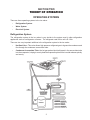
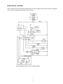
SECTION ONE
INSTALLATION CONSIDERATIONS
LOCATION
The ice maker may be closed in on the top, rear and two sides. The front MUST BE unobstructed for
proper air circulation and operation.
Installation should be such that the unit can be moved forward for servicing.
The installed area should be well ventilated, with ambient temperatures above 55°F (13°C) and below
110°F (43°C). BEST RESULTS ARE OBTAINED BETWEEN 70°F (21°C) AND 90°F (32°C).
The ice maker MUST BE installed in an area protected from the elements, such as wind, rain, water
spray or drips.
Provisions for electricity, water supply and drainage should be determined prior to installation.
ELECTRICAL REQUIREMENTS
The ice maker requires an electrical branch circuit of 120 VAC, 60 Hz, single phase 15 amp. delayed
action fuse or circuit breaker.
It is recommended that the ice maker is the only appliance plugged into the receptacle. Do not use an
extension cord. Do not use a receptacle that is controlled by a wall switch.
ELECTRICAL GROUND IS REQUIRED ON THIS APPLIANCE. DO NOT, UNDER ANY CIRCUMSTANCES, REMOVE THE POWER SUPPLY CORD GROUND PRONG.
WATER CONNECTION REQUIREMENTS
Materials needed for installation:
•
•
•
¼” OD copper tubing
¼” outlet, saddle-type shut-off valve
(part no. 541057)
¼” x ¼” tube union
(part no. 533812)
These materials can be obtained locally at a plumbing supply house or from FSP Parts Distribution by
ordering “Ice Maker Installation Kit” part no. 978567, which includes 25’ of copper tubing. Do not
use plastic tubing because it becomes brittle with age.
DRAIN CONNECTION REQUIREMENTS
The ice maker is equipped with a gravity drain or internal drain pump. The internal drain pump can be
installed separately and is available from FSP Parts Distribution (Part No. 2185528).
The ideal installation has a standpipe (minimum 1¼” diameter) installed directly below the outlet of the
drain tube.
1
-- NOTES --
2
SECTION TWO
THEORY OF OPERATION
OPERATING SYSTEMS
There are three operating systems in the ice maker:
•
Refrigeration System
•
Water System
•
Electrical System
Refrigeration System
The refrigeration system in the ice maker is very similar to the system used in other refrigeration
appliances such as a refrigerator or freezer. The refrigerant used in this unit is R-134a.
There are two very important additions to the refrigeration system in the ice maker:
•
Hot Gas Valve - This valve allows high pressure refrigerant gas to bypass the condenser and
flow through the condenser accumulator tube.
•
Condenser Accumulator Tube - the hot gas pushes liquid refrigerant in the accumulator tube
into the evaporator, helping to evenly heat the evaporator plate so the ice slab releases quickly
and evenly.
3
Water System
The water system provides the fresh water necessary for ice production and recycling this water as ice
is produced. The water system also flushes away rejected minerals and contaminates, circulates
cleaning solution during the CLEAN CYCLE and provides a means of drainage.
The hardness of the water supplied to the ice maker will affect the quality of the ice produced and may
also affect the operation of the water system. (See Chart in Section Five, TROUBLESHOOTING and
DIAGNOSTICS, page 16.)
A water softener or polyphosphate feeder will not cure all the problems associated with hard water, but
they can be used to reduce scale buildup in the ice maker. NOTE: Some polyphosphate feeders will
cause a slime buildup in the water system when the water supply has a low mineral content.
DISTRIBUTOR
EVAPORATOR
FREEZING PLATE
CUTTING GRID
WATER
RECIRCULATING
PUMP
OUTLET TUBE
BIN
WATER
RECIRCULATING
PUMP
RESERVOIR PAN
DRAIN
OVERFLOW
TUBE
WATER INLET
TUBE
(From Cold
Water Supply)
WATER INLET
VALVE
(flow rate:
.31 gpm)
TO BIN
DRAIN
FROM WATER
SUPPLY
4
ELECTRICAL SYSTEM
The ice maker’s electrical system provides power for the refrigeration and water systems to operate,
and controls the operational cycling of the ice maker.
Wiring Diagram shows unit in Ice Making Mode
5
OPERATIONAL CYCLES
There are three operational cycles of the ice maker:
•
ICE MAKING CYCLE
•
HARVEST CYCLE
•
DIAGNOSTIC/CLEAN CYCLE
In addition, there are two operational OFF cycles of the ice maker:
•
OFF CYCLE when the bin is full of ice and the service control switch is turned “ON”.
•
OFF CYCLE when the bin is full and the service control switch is turned “OFF” while power is
still supplied to the unit.
Ice Making Cycle
Electrical System
In the electrical system, power is supplied through the service control switches to the primary side of
the voltage step down transformer (120VAC to 8.7VAC for the cutter grid and bin light) and the electronic control board. The electronic control board in turn supplies 120 VAC to the water recirculating
pump, water inlet valve, hot gas solenoid, condenser fan motor and compressor.
Refrigeration System
In the refrigeration system, the hot gas refrigerant, under high pressure, is forced through the condeser
into a liquid, and flows through the drier and capillary tube into the evaporator. Under low presure in
the evaporator, the liquid refrigerant absorbs heat from the water flowing over the evaporator. The
refrigerant evaporates into a gas and passes into the accumulator. As a low-pressure gas, the refrigerant flows back through the suction line of the heat exchanger to the compressor.
During ICE MAKING cycle, some of the hot gas that is in the condenser accumulating tube condesnses
to a liquid and remains in the accumulating tube.
During the later stages of the ICE MAKING cycle, as the ice slab forms on the evaporator freezing
plate, some of the refrigerant passing through the evaporator will not evaporate into a gas, but will
remain a liquid. This liquid refrigerant will settle in the accumulator while the refrigerant vapor is
sucked off through the suction tube at the top of the accumulator. This accumulated liquid refrigerant
will eventually be evaporated by the warmed refrigerant gas passing through the accumulator during
the HARVEST cycle and during the beginning of the next ICE MAKING cycle.
NOTE: It is very important the accumulator is not tilted out of a horizontal position.
Water System
In the water system, the water recirculating pump moves the water from the reservoir pan up to the
distributor, where it flows out over the evaporator freezing plate.
Water that does not freeze on the evaporator plate runs off the front edge and falls back into the
reservoir, where it is recycled back to the distributor.
As the ice slab forms, the minerals in the water are on the surface of the ice. The water flowing over
the top of the ice slab washes these minerals back into the water reservoir pan. The water continues
to recycle until the ice slab reaches the desired thickness.
6
Harvest Cycle
Electrical System
In the electrical system, when the set temperature of the evaporator thermistor is reached, the evaporator thermistor terminates power to the condenser fan and water recirculating pump, and supplies
power to the hot gas valve solenoid and the water fill valve solenoid.
Refrigeration System
In the refrigeration system, the hot gas valve opens, allowing high pressure refrigerant gas to bypass
the condenser and flow through the condenser accumulating tube. The hot gas pushes the liquid
refrigerant that has accumulated in the accumulator tube up into the evaporator. The hot liquid refrigerant evenly heats the evaporator plate so the ice slab releases quickly and evenly.
The ice slab, when released, slides off of the evaporator plate onto the cutter grid.
Water System
In the water system, the water valve opens, allowing water to flow into the water reservoir pan. As the
reservoir fills, the mineral-laden water from the previous ICE MAKING cycle is flushed out the overflow
tube.
As a result of the hot gas flow and the and the ice sliding off evaporator plate, the temperature rises,
and the evaporator thermistor switches the unit to the ICE MAKING cycle. This cycling, between the
ICE MAKING cycle and the HARVEST cycle, continues until the ice bin is full.
Table 1-1 shows how the electronic control board controls the various components and systems in the
ice maker for each of the ICE MAKING CYCLE and HARVEST CYCLE.
When the ice maker’s service control switch is in the “ON” position, and the bin is not full of ice, the
evaporator thermistor determines whether the unit will be in the ICE MAKING CYCLE or the HARVEST CYCLE.
ON CYCLE
SECONDS
POWER ON START UP ONLY
120
60
120
ICE MAKING
HARVEST
>6.5°F
<52°F
WATER VALVE
CONDENSER FAN
HOT GAS VALVE
WATER RECIRC. PUMP
COMPRESSOR
Table 1-1
7
OPERATION
ICE BIN FULL
<35°F
*ICE BIN NOT FULL
>41°F
Clean Cycle
Electrical System
In the electrical system, power is supplied to the water recirculating pump through the service control
switch.
Water System
In the water system, water recirculating pump circulates the cleaning solution that has been added to
the reservoir up to the distributor, across the evaporator, and back into the reservoir where it is recirculated while the service control switch is in the “CLEAN” position.
Table 1-2 shows how the electronic control board controls the various components and systems
during the DIAGNOSTIC/CLEAN CYCLE.
CLEAN CYCLE
SECONDS
5
DIAGNOSTICS
5
5
5
5
CLEAN CYCLE
47 MINUTES
WATER VALVE
CONDENSER FAN
HOT GAS VALVE
WATER RECIRC. PUMP
COMPRESSOR
LED
The first 25 seconds of this cycle will operate each one of the electrical components for five (5)
seconds each.
Table 1-2
8
SECTION THREE
COMPONENT ACCESS
COMPONENT LOCATION
Low Voltage
Transformer
Light
Switch
Electronic
Control
Board Push-Button
Switches
LED
Evaporator
Plate
Cutter
Grid
Water
Recirculating
Pump
Compressor
Condenser
Fan
Hot Gas Valve
(Behind condenser)
Water Inlet
Valve
Condenser
9
ACCESSING THE CONTROL BOX
Models with Full Length Doors (KitchenAid)
The control box is located behind the door on automatic ice makers with full length doors. (Fig. 3-1)
Control
Box
Fig. 3-1
Models with Shorter Length Doors
(Whirlpool)
The control box is located behind the control box escutcheon above the door on automatic ice makers
with shorter length doors.
(Fig. 3-7)
Removing the Control Box Escutcheon
1.
Disconnect the Ice Maker fro the electrical
power supply.
2.
Remove the two (2) Phillips-Head
screws securing the control box escutcheon to the mounting plate. (Fig. 3-8) Remove the control box escutcheon from the
mounting plate and disconnect the wires from
the switch assembly terminals. Set the control box escutcheon aside.
3.
Control Box
Escutcheon
Fig. 3-7
Remove the four (4) Hex-head screws securing the escutcheon mounting plate to the cabinet.
Fig. 3-8
Two (2) Screws
10
ACCESSING THE COMPONENTS IN THE CONTROL BOX
(This procedure is the same for long and short door units.)
Removing the Control Box
1.
Remove the three (3) Phillips-Head screws securing the cutter grid cover to the cutter grid.
(Fig. 3-2)
Three (3) Screws
Wiring Harness Plugs
Fig. 3-2
Fig. 3-3
2.
Disconnect the three wiring harness plugs from the connectors at the bottom of the control
box. (Fig. 3-3)
3.
Remove the Hex-head screw securing the
cutter grid mounting bracket to the right
side of the cabinet liner. (Fig. 3-4)
4.
Loosen, but do not remove the Hex-head
screws securing the cutter grid mounting
bracket to the left side of the cabinet liner.
(Fig. 3-4) Then, lift the front of the cutter
grid up to release the Hex-head screw
from the key slot in the left side mounting
bracket and pull the cutter grid from the
cabinet.
5.
Loosen
This Screw
Fig. 3-4
Remove the four (4) Hex-head screws
securing the control box to the top of the
ice maker cabinet. (Fig. 3-5)
NOTE: The screws at the front of the
control box are recessed.
6.
The control box can now be lowered into
the service position.
Fig. 3-5
11
Remove
This
Screw
Removing the Electronic Control Board
1.
With the control box in the service position, disconnect the three (3) wiring harness plugs from
the connectors on the electronic control board. (Fig. 3-9)
2.
Remove the two (2) Hex-head screws securing the electronic control board to the mounting
stubs in the control box. (Fig. 3-9)
Wiring Harness
Plug
Wiring Harness
Plug
Wiring
Harness
Plug
Fig. 3-9
Removing the Push Button Switch Assembly
The push button switch assembly can be removed with the control box remaining in the service position.
1.
Disconnect the wires from the switch assembly terminals.
2.
Remove the decorative overlay from the front of the control box. (Fig. 3-10)
Decorative
Overlay
Fig. 3-10
3.
Press in on the four locking tabs at the back of the switch assembly and push the entire switch
assembly.
NOTE: If the push button switch assembly must be replaced, the service replacement
assembly must be ordered by using the specific model number of the ice maker. The
service replacement switch assembly comes with a new decorative overlay.
12
ACCESSING THE COMPONENT COMPARTMENT
1.
Open the ice maker door and remove the
four (4) Phillips-Head screws securing the
component compartment front cover to
the cabinet. (Fig. 3-14)
2.
Pull the ice maker from its installed
position. It may be necessary to disconnect
the water supply line and drain line from the
ice maker.
3.
Screws
Leveling Leg
Turn the front leveling legs out until they
disengage from the cabinet. (Fig. 3-14)
Screws
Fig. 3-14
4.
Remove the two (2) front bolts securing
the component compartment base to the
cabinet.
5.
Tilt the entire ice maker cabinet back far enough to gain access to the component compart
ment. (Fig. 3-15) Be careful not to kink any of the sealed system tubing or pinch any wiring
while tilting the cabinet backward.
NOTE: Secure the cabinet to avoid any possibility that it will tip back any further or fall
forward while repairs are being performed.
Fig. 3-15
Removing the Condenser Fan
1.
Remove the two (2) Hex-head screws securing the condenser fan assembly to the condenser
and the two (2) Hex-head screws securing the condenser fan assembly to the component
compartment base. (Fig. 3-16)
2.
Remove the three (3) hex-head screws securing the fan motor to the fan bracket. (Fig. 3-17)
Screw
Screw
Screw
Screw
Fig. 3-16
13
Fig. 3-17
Removing the Water Valve
The water valve can be serviced with the unit in the installed position by removing the component
compartment cover.
1.
Disconnect the wiring harness connector
from the water valve solenoid terminals.
2.
Disconnect the water supply lines from the
inlet and outlet of the water valve.
NOTE: Water may be present in these lines.
Have a small pail available to bleed
lines.
3.
Remove the two (2) Hex-head screws
securing the water valve to the side of the
cabinet liner. (Fig. 3-18)
Fig. 3-18
Removing the Hot Gas Solenoid
The hot gas valve can be serviced with the unit tilted back in the service position.
1.
2.
Disconnect the wiring harness plug from
the solenoid terminals.
Screw
Remove the hex-head screw securing the
solenoid to the mounting bracket. (Fig. 3-19)
Solenoid
Fig. 2-19
14
SECTION FOUR
TROUBLESHOOTING AND DIAGNOSTICS
WATER AND ITS EFFECT ON ICE MAKING
Quality ice is defined as hard, clear, cold and free of taste or odor. All ice makers will provide this type
of quality ice only if the water used to produce the ice is pure and free of mineral or chemical contamination. The chart below helps diagnose problems that can affect ice production.
AFFECT ON ICE QUALITY
INGREDIENT
EFFECT
CORRECTION
Algae
Objectionable Taste and Odor
Carbon Filter
Minerals:
Sodium
Potassium
Magnesium
Calcium
Cloudy Ice
Slow Cutting
Refreezing
1. Check:
a. Water flow restriction
2. Polyphosphate feeder or
water softener
3. Change water source
AFFECT ON ICE MAKER
INGREDIENT
EFFECT
CORRECTION
Iron
Chlorine
Manganese
Staining (Aesthetics only)
1. Ice Machine Cleaner
P/N 8171307.
2. Water softener AND iron
filter
Permanent Hardness
Calcium or Magnesium
Sulfates
Chlorides
Nitrates
Scale
1. Abrasive cleaning
2. Polyphosphate feeder or
water softener reduces
or eliminates need for
abrasive cleaning
Temporary Hardness
Calcium or Magnesium
Carbonates
Scale
1. Liquid or nickel safe ice
machine cleaner
2. Polyphosphate feeder or
water softener reduces
frequency of cleaning by
50%
RECOMMENDATIONS:
Water softeners or polyphosphate feeders are not cure-alls, but do reduce and, in some cases,
prevent scale buildup. Use Ice Maker Cleaner (P/N 8171307).
CAUTION: Some polyphosphate feeders cause slime buildup. Their use in low mineral content
water should be carefully considered.
NOTE: Reverse Osmosis filters are NOT RECOMMENDED with this unit. These filter can limit
the water flow to the unit and limit its capacity to produce sufficient ice.
Water Hardness Test Kit: A Water Hardness Tes Kit (P/N 4171690) is available from FSP Part
Distribution.
15
SERVICING INFORMATION
SERVICEABLE ELECTRICAL COMPONENTS
SERVICEABLE PARTS
Part No.
Wattage
COMPRESSOR
Run Winding
Start Winding
RELAY
OVERLOAD
WATER RECIRC. PUMP
WATER VALVE ( .31 gpm)
SOLENOID COIL (HGV)
THERMISTOR (Bin)
THERMISTOR (Evap)
PC BOARD
TRANSFORMER
COND. FAN MOTOR
DRAIN PUMP (optional)
2176659
244
Resistance
1 - 5Ω
3 - 11Ω
2183410
2183404
2185748
2185531
759112
2185679
26 - 30
12 nom.
7-9
15.95Ω
277.5Ω
376Ω
10K@ 77°F (25°C)
2185680
2185621
2185657
2183437
2185528
10K@77°F (25°C)
23
360Ω
277 - 275Ω
6.9Ω
40
12 - 15
1.
Refrigerant charge must be applied to the high side only.
2.
This unit operates on 120 VAC except for the cutter grid, electronic control board and optional
light, which operate at 8.7 VAC.
3.
The transformer, cutter grid and electronic control board remain energized in ON and CLEAN
modes.
THERMISTOR OPERATING PARAMETERS
EVAPORATOR THERMISTOR
WATER VALVE OFF (during harvest)
CUT-OUT
CUT-IN
ICE THICKNESS
Temperature
Resistance
Temperature
Resistance
Temperature
Resistance
NORMAL
52.5°F ± .3°
18.7kΩ
Ω ± 1%
6.5°F ± .3°
69.3kΩ
Ω ± 1%
40°F ± .3°
25.9kΩ
Ω ± 1%
THICK
52.5°F ± .3°
18.7kΩ
Ω ± 1%
4.5°F ± .3°
73.5kΩ
Ω ± 1%
40°F ± .3°
25.9kΩ
Ω ± 1%
THIN
52.5°F ± .3°
18.7kΩ
Ω ± 1%
8.5°F ± .3°
65.3kΩ
Ω ± 1%
40°F ± .3°
25.9kΩ
Ω ± 1%
ICE BIN THERMISTOR
BIN SHUT-OFF
Temperature
Resistance
Temperature
Resistance
40°F ± 1°
25.9kΩ
Ω ± 3%
35°F ± 1°
29.8kΩ
Ω ± 3%
If evaporator thermistor is not present or open, the electronic control will continue to make ice based
on time instead of temperature. (20 minutes for ice making and 3 minutes for harvest.)
16
SECTION FIVE
TECH TIPS
WIRING DIAGRAM
Wiring Diagram shows unit in Ice Making Mode.
17
STRIP CIRCUITS
1.
Ice Making Mode
NOTE: If the unit is run throught the Ice Maing Mode with no water running across the Evaporator
Plate, a complete frost pattern will appear. After three (3) minutes, the unit will go into the Harvest
Mode.
2.
Harvest Mode
18
3.
First 25 Seconds of Diagnostics/Clean Mode
Each switch on the Electronic Control Board closes for five (5) seconds in consecutive order.
LED remains on through entire Diagnostic Cycle.
3.
Last 47 Minutes of Diagnostics/Clean Mode
LED reamins on throughout entire Clean Cycle.
19
CYCLE CHARTS
ON CYCLE
SECONDS
OPERATION
POWER ON START UP ONLY
120
60
120
ICE MAKING
HARVEST
>6.5°F
<52°F
WATER VALVE
CONDENSER FAN
HOT GAS VALVE
WATER PUMP
COMPRESSOR
ICE BIN FULL *ICE BIN NOT FULL
<35°F
>41°F
* Return to Ice Making
CLEAN CYCLE
SECONDS
5
DIAGNOSTICS
5
5
5
CLEAN CYCLE
47 MINUTES
5
WATER VALVE
CONDENSER FAN
HOT GAS VALVE
WATER PUMP
COMPRESSOR
LED
Press CLEAN switch for diagnostic mode.
To exit Clean/Diagnostic Cycle press ON or OFF.
If a short or open thermistor is detected the LED will flash for 5 seconds before the Clean Cycle is
started.
THERMISTOR OPERATING PARAMETERS
EVAPORATOR THERMISTOR
ICE THICKNESS
WATER VALVE OFF (during harvest)
CUT-OUT
CUT-IN
Temperature
Resistance
Temperature
Resistance
Temperature
Resistance
NORMAL
52.5°F ± .3°
Ω ±1%
18.7kΩ
6.5°F ± .3°
Ω ±1%
69.3kΩ
40°F ± .3°
Ω ±1%
25.9kΩ
THICK
52.5°F ± .3°
18.7kΩ
Ω ±1%
4.5°F ± .3°
73.5kΩ
Ω ±1%
40°F ± .3°
25.9kΩ
Ω ±1%
THIN
52.5°F ± .3°
18.7kΩ
Ω ±1%
8.5°F ± .3°
65.3kΩ
Ω ±1%
40°F ± .3°
25.9kΩ
Ω ±1%
The evaporator thermistor is clipped to the outlet tubing of the accumulator after the 180° bend.
If evaporator thermistor is not present or open, the electronic control will continue to make ice based
on time instead of temperature. (20 minutes for ice making and 3 minutes for harvest.)
ICE BIN THERMISTOR
BIN SHUT-OFF
Temperature
Resistance
Temperature
Resistance
40°F ± 1°
25.9kΩ
Ω ±3%
35°F ± 1°
29.8kΩ
Ω ±3%
20
CIRCUIT BOARD JUMPERS
(To Adjust Ice Thickness)
P1
CODE
P1
CODE
1
4
1
4
NORMAL
3
6
Cut-Out Values
6.5°F ± .3°
Ω ±1%
69.3kΩ
P1
CODE
1
THICK
3
6
Cut-Out Values
4.5F ± .3°
Ω±1%
73.5kΩ
21
4
THIN
3
6
Cut-Out Values
8.5F ± .3°
Ω±1%
65.3kΩ
Optional Drain Pump
The optional drain pump consists of a motor, a pump that is magnetically coupled to the motor, a water
reservoir with sensing devices and an electronic control board that controls the water level in the
reservoir by using the sensing probes.
How It Works
1.
Water enters the drain pump reservoir from
the ice machine bin drain and the overflow
tube in the water reservoir.
2.
The drain pump reservoir has three probes
for sensing water level:
•
High Water Cut-In
•
High Water Shut Off
•
Common
As the water level rises to contact the high water cut-in probe in the reservoir, a signal is sent
to the electronic control board. The control board performs a low voltage comparison by water
contact between the high water cut-in and common probes. If water is contacting both probes
the pump motor turns on and the pump runs.
Once the water level drops and breaks the contact between the high water cut-in and common
probes, the electronic control board will turn the pump motor off after a built-in 12 second
delay. This delay prevents the motor from short cycling and over heating.
3.
If the the drain outlet becomes clogged to the point where water will not be allowed to be
pumped out or a large volume of water enters the reservoir quickly, the high water shut off
probe will come in contact with the water. If this occurs, the signal sent to the electronic control
board will trigger a complete shut down of the ice machine. The pump motor will continue to
function in this mode until the reservoir is empty or the motor cycles off from over heating.
(The motor is equipped with a resettable thermal fuse.)
Drain Pump Installation
1.
Pull the ice machine from its installed position.
2.
Disconnect the power supply cord from the wall outlet.
3.
Remove the seven screws securing the rear component compartment cover to the cabinet.
4.
Slide the drain pump into the back of the cabinet.
5.
If the unit already has a drain tube connected
to the ice bin outlet, remove it and the clamp
attached to the bin. (Clamp will be used later.)
Ice Bin
6.
Install the new drain tube (Part No. 2185672)
provided in the drain pump kit. Use the clamp
removed earlier to secure the new drain tube
to the bin. (Fig. 1).
Condenser
Fig. 1
Drain Tube
(Bin to Pump)
Drain Pump
Reservoir Inlet
22
Drain Pump
7.
Install the drain pump. Carefully slide in, aligning
the tab on the pump base to the rectangular slot
in the unit base. (Fig. 2)
Pump Mounting
Tab
Fig. 2
8.
Attach the drain tube from the bin to the pump inlet. Install the vent tube and drain tube to the
household drain before securing the pump to the unit base. The vent tube and drain tube
should be threaded through the component compartment cover. (Fig. 3)
Vent Tube
Drain Tube
(Pump to
Household
Drain)
Drain Tube
(Pump to
Household
Drain)
Drain Pump
Fig. 3
Pump Mounting
Screws
9.
Coil the power cord from the Ice Maker into a figure 8. Wrap electrical tape around the center
of the figure 8. Place the wrapped cord between the compressor and the drain pump. Install
the plug on the power cord to the electrical outlet of the drain pump.
10.
Line up the two (2) holes at the rear of the pump with the two holes in the unit base and install
two (2) #8 x ½” hex-head screws. (Fig. 3)
11.
Secure the vent tube to the back of the ice maker
using three (3) clamps and three (3) #8 x ½”
hex-head screws supplied in the drain pump
kit. (Fig. 4)
Vent
12.
Check all connections for leaks.
13.
Reinstall the component compartment cover.
14.
Connect the power cord from the drain pump to
the house hold electrical supply in accordance
with National Electrical Code and local codes
and ordinances.
Tube
23
Fig. 4
Vent Tube
Mounting
Clamp &
Screw
MODEL/SERIAL NUMBER PLATE
SERIAL NUMBER DESIGNATOR
SERIAL NUMBER
E J
MANUFACTURING SITE
E = Evansville, IN
YEAR OF MANUFACTURE
J = 1999
WEEK OF MANUFACTURE
PRODUCT SEQUENCE NUMBER
36 50001
Model/Serial
Number Plate
ALL BRANDS
(Left Side of
Cabinet Liner)
WHIRLPOOL MODEL NUMBER
DESIGNATOR
MODEL NUMBER
G I 1500 X H N 0
PRODUCT GROUP
G = Gold Series
PRODUCT IDENTIFICATION
I = Ice Maker
MODEL SIZE
1500 = 15” Width
FEATURE/VARIATION
X = Feature Not Defined
YEAR OF INTRODUCTION
H = 1999
COLOR CODE
W = White
N = Almond
B = Black
ENGINEERING CHANGE
0 = Basic Release; 1 = First Revision; 2 = Second Revision
KITCHENAID MODEL NUMBER
DESIGNATOR
MODEL NUMBER
K UI S 15 5 H WH 0
PRODUCT GROUP
K = KITCHENAID
PRODUCT IDENTIFICATION
UI = Undercounter Ice Maker
MERCHANDISING SCHEME
S = Standard
MODEL SIZE
15 = 15” Width
FEATURE/VARIATION
5 = 50 Pounds
YEAR OF INTRODUCTION
H = 1999
COLOR CODE
WH = White
NL = Almond
BL = Black
SS = Brushed Stainless Steel SB = Brushed Stainless/Black
ENGINEERING CHANGE
0 = Basic Release; 1 = First Revision; 2 = Second Revision
24
KitchenAid ICE MAKER WARRANTY
ONE-YEAR FULL WARRANTY ON ICE MAKER
For one year from the date of purchase when this product is operated in a residential or light commercial setting,
and is maintained according to the instructions furnished with the product, KitchenAid will pay for FSP® replacement parts and repair labor to correct defects in materials or workmanship. Service must be provided by a
KitchenAid designated service company.
FIVE-YEAR FULL WARRANTY
In the second through fifth years from the date of purchase, KitchenAid will pay for replacement parts and
repair labor costs to correct defects in materials or workmanship in the sealed refrigeration system. These
parts are compressor, evaporator, condenser, drier and connecting tubing. Service must be performed by a
KitchenAid designated service company.
KitchenAid will not pay for:
1. Service calls to correct the installation of your ice maker, to instruct you how to use your ice maker, to
replace house fuses or correct house wiring or plumbing, or replace light bulbs.
2. Repairs when your ice maker is used in locations where usage exceeds ice making capabilities of unit
(about 50 pounds in 24 hours.) This ice maker is intended only for residential and/or light commercial use
that does not exceed these capabilities.
3. Damage resulting from accident, alteration, misuse, abuse, fire, flood, acts of God, improper installation or
installation not in accordance with local electrical or plumbing codes or use of product not approved by
KitchenAid.
4. Replacement parts or repair labor costs for units operated outside the Untied States.
5. Pickup and delivery. This product is designed to be repaired in the home.
6. Repairs to parts or systems resulting from unauthorized modifications made to the appliance.
KITCHENAID CORPORATION SHALL NOT BE LIABLE FOR INCIDENTAL
OR CONSEQUENTIAL DAMAGES.
Some states do not allow the exclusion or limitation of incidental or consequential damages, so this exclusion
or limitation may not apply to you. This warranty gives you specific legal rights, and you may also have other
rights which vary from state to state.
Outside the United Stares, a different warranty may apply. For details please contact your authorized
KitchenAid dealer.
If need service, first see the “Troubleshooting” section of this book. After checking “Troubleshooting”, additional help can be found by checking the “Requesting Assistance or Service” section by calling the KitchenAid
Consumer Assistance Center, 1-800-422-1230 (toll-free) from anywhere in the U.S.A.
2/99
For warranty information in Canada:
Please contact your authorized KitchenAid dealer or call Consumer Assistance at 1-800-461-5681 (toll-free)
between 8:30 a.m. and 6 p.m. EST from anywhere in Canada.
25
WHIRLPOOL ICE MAKER WARRANTY
ONE-YEAR FULL WARRANTY ON ICE MAKER
For one year from the date of purchase when this product is operated in a residential or light commercial setting,
and is maintained according to the instructions furnished with the product, Whirlpool will pay for FSP® replacement parts and repair labor to correct defects in materials or workmanship. Service must be provided by a
Whirlpool designated service company.
FIVE-YEAR FULL WARRANTY
In the second through fifth years from the date of purchase, Whirlpool will pay for replacement parts and repair
labor costs to correct defects in materials or workmanship of the compressor only. Service must be performed
by a Whirlpool designated service company.
Whirlpool will not pay for:
1. Service calls to correct the installation of your ice maker, to instruct you how to use your ice maker, to
replace house fuses or correct house wiring or plumbing, or replace light bulbs.
2. Repairs when your ice maker is used in locations where usage exceeds ice making capabilities of unit
(about 50 pounds in 24 hours.) This ice maker is intended only for residential and/or light commercial use
that does not exceed these capabilities.
3. Damage resulting from accident, alteration, misuse, abuse, fire, flood, acts of God, improper installation or
installation not in accordance with local electrical or plumbing codes or use of product not approved by
Whirlpool.
4. Replacement parts or repair labor costs for units operated outside the Untied States.
5. Pickup and delivery. This product is designed to be repaired in the home.
6. Repairs to parts or systems resulting from unauthorized modifications made to the appliance.
KITCHENAID CORPORATION SHALL NOT BE LIABLE FOR INCIDENTAL
OR CONSEQUENTIAL DAMAGES.
Some states do not allow the exclusion or limitation of incidental or consequential damages, so this exclusion
or limitation may not apply to you. This warranty gives you specific legal rights, and you may also have other
rights which vary from state to state.
Outside the United Stares, a different warranty may apply. For details please contact your authorized
Whirlpool dealer.
If need service, first see the “Troubleshooting” section of this book. After checking “Troubleshooting”, additional help can be found by checking the “Requesting Assistance or Service” section by calling the Whirlpool
Consumer Assistance Center, 1-800-422-1230 (toll-free) from anywhere in the U.S.A.
2/99
For warranty information in Canada:
Please contact your authorized Whirlpool dealer or call Consumer Assistance at 1-800-461-5681 (toll-free)
between 8:30 a.m. and 6 p.m. EST from anywhere in Canada.
26
27
28
29
30
31
32
33
34