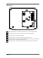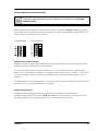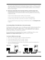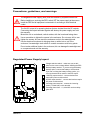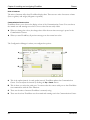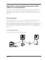
1
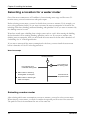
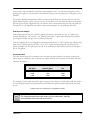
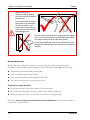
user manual © 2008 Phason Inc. All rights reserved. Printed in Canada 25047101 2008-06-23 i Limited warranty Software Phason Inc. (Phason) warrants for a period of 90 days from the date of purchase that the software product will execute its programming instructions when properly installed on the personal computer or workstation indicated on this package. Phason does not warrant that the operation of the software will be uninterrupted or error free. Should this software product fail to execute its programming instructions during the warranty period, the purchaser’s remedy shall be to return the software CD (media) to Phason for replacement. Should Phason be unable to replace the media within a reasonable amount of time, the purchaser’s alternate remedy shall be a refund of the purchase price upon return of the product and all copies. Media Phason warrants the media upon which this product is recorded to be free from defects in materials and workmanship under normal use for a period of 90 days from the date of purchase. Should the media prove to be defective during the warranty period, the purchaser’s remedy shall be to return the media to Phason for replacement. Should Phason be unable to replace the media within a reasonable amount of time, the purchaser’s alternate remedy shall be a refund of the purchase price upon return of the product and all copies. Notice of warranty claims The purchaser must notify Phason in writing of any warranty claim no later than 30 days after the warranty period expires. Limitation of warranty Phason makes no other express warranty, whether written or oral, with respect to this product. Any implied warranty of merchantability or fitness is limited to the 90 days of this written warranty. Some states or provinces do not allow limitations on how long an implied warranty lasts, so the above limitation or exclusion may not apply to you. This warranty gives specific legal rights and you may have other rights, which vary from state to state, or province to province. Exclusive remedies The remedies provided above are the purchaser’s sole and exclusive remedies. Phason shall not be liable for any direct, indirect, special, incidental, or consequential damages (including lost profit) whether based on warranty, contract, tort, or any other legal theory. Some states or provinces do not allow the exclusion or limitation of incidental or consequential damages, so the above limitation or exclusion may not apply to you. Warranty service Warranty service may be obtained from the Phason office location indicated in the user manual or service booklet. ii Service and technical support Phason will be happy to answer all technical questions that will help you use FlowMiser. Before contacting Phason, check the following: Read the manual for information about the window with which you are having trouble. If you still have a problem with FlowMiser, collect the following information: Any messages displayed by the FlowMiser software A description of the problem A description of what you were doing before the problem occurred The model and serial number of the Flow Monitor Information about the equipment, such as a water meter, you are monitoring My dealer’s name: How to contact my dealer: Street/PO Box City State/Province Zip/Postal Phone Fax E-mail Web site 2 Terracon Place Winnipeg, Manitoba Canada R2J 4G7 Phone: Fax: E-mail: Web site: 204-233-1400 204-233-3252 [email protected] www.phason.ca iii iv Table of contents Chapter 1: Introducing FlowMiser ...................................................................................................1 Introducing FlowMiser...............................................................................................................................2 Uses of FlowMiser.................................................................................................................................2 FlowMiser features................................................................................................................................2 FlowMiser system components ............................................................................................................3 FlowMiser windows...............................................................................................................................3 Computer requirements........................................................................................................................7 About this manual .....................................................................................................................................7 Styles used in this manual ....................................................................................................................7 Chapter 2: Installing the hardware ..................................................................................................9 Selecting a location for a water meter ....................................................................................................10 Selecting a water meter ......................................................................................................................10 Phason Flow Monitor installation guide..................................................................................................12 Features ..............................................................................................................................................12 Electrical ratings .................................................................................................................................12 Parts list...............................................................................................................................................12 Precautions, guidelines, and warnings...............................................................................................13 PFM layout ..........................................................................................................................................15 Installing the PFM ...............................................................................................................................16 Installing the PFM ...............................................................................................................................16 Maintaining the PFM ...........................................................................................................................20 Regulated Power Supply installation guide ............................................................................................21 RPS electrical ratings..........................................................................................................................21 Determining maximum cable length...................................................................................................22 Precautions, guidelines, and warnings...............................................................................................23 Regulated Power Supply layout .........................................................................................................23 Chapter 3: Installing and configuring FlowMiser ..........................................................................25 Installing FlowMiser.................................................................................................................................26 Registering FlowMiser ........................................................................................................................26 Configuring FlowMiser ............................................................................................................................27 Configuring site identification .............................................................................................................27 Configuring FlowMiser options...........................................................................................................28 Adding, editing, and removing Flow Monitors....................................................................................31 Configuring pulse counters ................................................................................................................32 Configuring the FlowMiser e-mail and fax clients...............................................................................36 Setting up flow alarms.............................................................................................................................37 v Chapter 4: Creating charts and reports ........................................................................................41 FlowMiser Status Viewer .........................................................................................................................42 Viewing charts .........................................................................................................................................43 Viewing Usage Charts ........................................................................................................................43 Viewing Flow Rate Charts ...................................................................................................................45 Selecting date ranges .........................................................................................................................46 Zooming and panning charts .............................................................................................................47 Creating reports ......................................................................................................................................48 Usage Reports ....................................................................................................................................48 Flow Rate Reports...............................................................................................................................50 Alarm History Reports.........................................................................................................................51 Configuration Reports.........................................................................................................................52 Scheduling automatic reports.............................................................................................................53 Appendixes ....................................................................................................................................55 Appendix A: Troubleshooting .................................................................................................................56 Appendix B: Using shielded twisted pair (STP) cable for communications ...........................................57 STP requirements ...............................................................................................................................57 Index........................................................................................................................................................59 vi vii Chapter 1: Introducing FlowMiser This chapter introduces you to FlowMiser and the layout of this manual. Read this chapter before reading the rest of the manual. Introducing FlowMiser About this manual FlowMiser windows 2008-06-23 1 Chapter 1: Introducing FlowMiser Introducing FlowMiser The FlowMiser software works with the Phason Flow Monitors to automatically monitor flow rates and usage, and provides tools to help you analyze and add intelligence to the information. Each Phason Flow Monitor has five pulse counting inputs, to which you can connect any dry contact switch, for example, a flow meter or tipping bucket with pulse output. Uses of FlowMiser One of the main uses for FlowMiser is monitoring water flow rates and usage in livestock operations. FlowMiser can help producers ensure that water systems are intact, working efficiently and economically for producing and maintaining healthy, productive animals. FlowMiser can help livestock producers, and others with similar needs, ensure effective management of a critical resource, water, while identifying and controlling cost. Other uses of FlowMiser include: Greenhouses and plant propagation facilities – plants have highly-sensitive needs for controlled water and nutrient supply. FlowMiser can monitor water and water-soluble fertilizer systems. Vehicle and equipment wash stations Residential or municipal water supply systems, especially those supplied from remote locations Fluid management – facilities that manage gases or liquids that flow through a meter can use FlowMiser to find ways to reduce risk, assure high performance, and lower costs. FlowMiser features Automatic data collection – the system automatically counts pulses from any dry contact pulse output and then converts the data to flow rate and usage, in weight or volume. Information at a glance – the FlowMiser Status Viewer displays flow rate, usage, and alarm information for all your Phason Flow Monitors. Informative, easy-to-interpret management charts and reports 2 Flow Rate Chart – displays flow rates for the selected pulse counters, over a date range. Flow Rate Report – displays flow rates for the selected pulse counters, over a date range. Usage Chart – displays daily usage for a single pulse counter, over a date range. Usage Report – displays daily and total usage for multiple pulse counters, over a date range. Alarm History Report – displays a list of all alarm conditions, sorted by date. Configuration Report – displays configuration and settings for all Phason Flow Monitors. Phason Introducing FlowMiser FlowMiser system components A FlowMiser system consists of the following: A B D E C A FlowMiser software B Personal computer1 C RS-485A Converter D Phason Flow Monitor (PFM)2 E Phason Regulated Power Supply (RPS)3 1 For a complete list of computer requirements, contact Phason technical support. 2 A FlowMiser system can have up to 32 Phason Flow Monitors. 3 One RPS can provide power for up to 11 Phason Flow Monitors. FlowMiser windows There are several windows in FlowMiser that you should be familiar with before you begin working with the program. The four main windows are: the Communication Center, Configuration Manager, Settings Manager, and Reports Manager. There are detailed descriptions of each window later in the manual. 2008-06-23 3 Chapter 1: Introducing FlowMiser Communication Center The Communication Center is the main window for FlowMiser. The Communication Center displays all the communication messages from the FlowMiser software and Flow Monitors. Opens the Settings Manager Opens the Configuration Manager Opens the Reports Manager Opens the Status Viewer 4 Phason Introducing FlowMiser Configuration Manager The Configuration Manager is where you configure the system options and Flow Monitors. From the Configuration Manager, you can: Enter site identification (on page 27) Configure FlowMiser options (on page 28) Add, edit, and remove Flow Monitors (on page 31) Configure pulse counters (on page 32) Configure the FlowMiser e-mail and fax clients (on page 36) 2008-06-23 5 Chapter 1: Introducing FlowMiser Settings Manager The Settings Manager is where you set up sample durations and alarms. From the Settings Manager, you can set up alarms and sample durations (on page 37). Reports Manager The Reports Manager is where you create charts and reports. From the Reports Manager you can: View charts (on page 43) Create reports (on page 48) Schedule automatic reports (on page 53) 6 Phason About this manual Computer requirements Customers who need to purchase a computer to run FlowMiser must purchase one that meets certain requirements. For the latest computer and system requirements, contact Phason Customer Support at 204-233-1400 or [email protected]. About this manual This manual describes the features of FlowMiser and how to use them. In addition to reading this manual, you should be familiar with the following: Microsoft Windows™: how to perform basic Windows functions such as opening and closing windows, finding and opening files, saving and closing files, as well as using a mouse and keyboard. Phason Flow Monitor (PFM) and equipment connected to it, such as water meters, tipping buckets, and dry contact switches. Styles used in this manual The following styles are used in this manual: All buttons and tabs are bolded. For example: click OK to save the changes. All filenames and directories are in a monospace font. For example, the default directory is C:\Program Files\Phason\FlowMiser. Hint/tip This is a hint or tip. It contains helpful information that may make it easier for you to set up or use FlowMiser. 2008-06-23 7 Chapter 1: Introducing FlowMiser Note This is a note. It contains important information that may help you better understand FlowMiser. A copy of this manual is also on the FlowMiser installation CD. The PDF (Adobe Acrobat™ Portable Document Format) file installs in C:\Program Files\Phason\FlowMiser\ HelpDocs during a normal installation. You can view the file by opening it using Adobe Acrobat Reader™, version 5 or higher, or by clicking any of the Help buttons in the software. 8 Phason Chapter 2: Installing the hardware This chapter contains hardware installation instructions and guidelines for installing water meters. Selecting a location for a water meter Phason Flow Monitor installation guide Regulated Power Supply installation guide 2008-06-23 9 Chapter 2: Installing the hardware Phason Selecting a location for a water meter One of the most-common uses of FlowMiser is for monitoring water usage and flow rates. To monitor water, you need a water meter with pulse output. Before selecting a water meter, you need to decide what you want to measure. If, for example, you are at a hog production facility, do you want to measure the water consumption of the whole site, including wash-down, drinking, medicated drinking, and sprinklers? Or do you want to measure only the drinking water in a room? Water lines usually enter a building from a single source such as a well. After entering the building, the line branches off for washing, drinking, sprinklers, and so on. If you want to measure only drinking water consumption, then you must install the water meter in the line after it branches off for drinking. See ‘A’ in the diagram below. If you want to measure all the water consumption for the barn, you must install the water meter before it branches off. See ‘B’ in the diagram below. Water line example Incoming water line B Line branches off for medicated drinking water A Water meter for measuring drinking water consumption A Line branches off for drinking water Line branches off for sprinkler water B Water meter for measuring all water consumption Selecting a water meter After selecting which water consumption you want to measure, you need to select a water meter. When selecting a water meter, you need to consider the expected peak flow rate of the water line. The peak flow rate is the maximum flow rate of the water line. 10 2008-06-23 Ask yourself, “How detailed do I need my measurements to be?” A water meter that puts out ten pulses per US gallon is very detailed. A water meter that puts out one pulse per ten US gallons is less detailed. If you want detailed measurements and do not expect a peak flow rate of more than one unit (US gallon, Imperial gallon, and so on) per second, you can choose a water meter that puts out 10 pulses per unit. If you expect a high flow rate, you need to select a water meter that puts out one pulse per 10 units. For a very high flow rate, select a water meter that puts out one pulse per 100 units. Peak flow rate example If the expected peak flow rate is 100 US gallons per minute, then there are only 1.67 gallons per second (100 gallons ÷ 60 seconds = 1.67 gallons per second). A pulse meter putting out one pulse per US gallon would only put out 1.67 pulses per second. If in the example above, we changed the expected peak flow rate to 750 US gallons per minute, then there are 12.5 gallons per second (750 ÷ 60 = 12.5). A pulse meter putting out one pulse per US gallon would put out 12.5 pulses per second. You would need a water meter that put out one pulse per 10 US gallons. Conversion table The table below shows the conversion for a one pulse per unit output. If you need to convert the pulse output to a different unit of measure or output, look up the conversion in the table, and then calculate the output. Pulses per US gallon Pulses per Imperial gallon Pulses per litre 1.000 0.833 3.788 1.200 1.000 4.545 0.264 0.220 1.000 For example, if your water meter has a pulse output of one pulse per ten US gallons and you need to convert the pulse output into pulses per litre, then divide the pulses per litre output from the chart by ten. Pulses per litre for a one pulse per 10 US gallons=0.0264 For information about the pulse output of your water meter, read the documentation that came with the product. 2008-06-23 11 Chapter 2: Installing the hardware Phason Phason Flow Monitor installation guide The Phason Flow Monitor (PFM) works with the FlowMiser software to automatically monitor flow rates and usage. The PFM has five pulse counting inputs, to which you can connect any dry contact switch, for example, a flow meter or tipping bucket with pulse output. Features Five pulse counting inputs Easy-to-follow installation instructions Low-maintenance design Large, rugged and durable enclosure (corrosion resistant, water resistant, and fire retardant) Two-year limited warranty Electrical ratings The required power supply is the Phason Regulated Power Supply (RPS). One RPS can provide power for up to 11 Phason Flow Monitors. For more information, read the RPS installation guide or contact your dealer. Power requirement: Power consumption: 10 to 14 VDC 100 mA Parts list The following are included in the box. Phason Flow Monitor Four mounting screws PFM installation guide 12 2008-06-23 In addition to the parts included with the PFM, you need to provide the following items. Item Notes Power supply Communication cable Phason Regulated Power Supply (RPS) Unshielded twisted pair (UTP), category 3 (CAT3) or category 5 (CAT5) OR Shielded twisted pair (STP), CAT3 or CAT5 (read the NOTE below) Four pair recommended Enough to go from the RS-485A to the Phason Flow Monitor Enough to go from the power supply to the PFM For more information, read Determining maximum cable length on page 22 Use at all cable entry points Power cable Watertight strain reliefs or conduit connectors If you are using STP cable, you must follow the specific instructions in Service Bulletin 24 – Using shielded twisted pair (STP) cable to connect Phason networkable devices. Precautions, guidelines, and warnings The Phason Flow Monitor must be installed by a qualified electrician. Before installing or servicing the Phason Flow Monitor, switch OFF the power supply at the source. Install the Phason Flow Monitor and all equipment connected to it according to local electrical codes. 2008-06-23 13 Chapter 2: Installing the hardware Phason Mount the unit on a sheltered, vertical surface, with the electrical knockouts facing down. Use a screwdriver to tighten the screws in the enclosure. Do not use a drill or over tighten the screws; this can crack the enclosure and ruin the watertight seal. Use the electrical knockouts for bringing wires or cables into or out of the enclosure. Use watertight strain reliefs or conduit connectors at all cable-entry points. Do not make additional holes in the enclosure; this can damage the watertight seal or components and void the warranty. Routing data wires Routing data wires in the same conduit as, or beside AC power cables, can cause electrical interference, erratic readings, and/or improper control. Data wires include all of the following: Temperature probe and humidity sensor cables Actuator feedback (potentiometer) wires Data communication wires, including RS-232/RS-485 Any cable or wire that does not provide AC power Guidelines for routing data wires Do not run the wires in the same conduit as AC power cables. Do not run the wires beside AC power cables or near electrical equipment. When crossing other cables or power lines, cross them at a 90-degree angle. If in doubt, do not run any wire or cable that is not an AC-power wire inside the same conduit or beside other AC-power wires. 14 2008-06-23 PFM layout A C B B D R1 R2 F E A Incoming power terminals – connect the incoming power (10 to 14 VDC) to these terminals. B Pulse count terminals (PC1 to PC5) – connect the dry contacts to these terminals. C Alarm relay terminal – not used in this application. D Communication socket – connect the communication wiring to this socket. E Termination resistors – if there are any devices on this communication channel after the PFM, then use wire cutters to remove only these two resistors (R1,R2). F Mounting holes (x4) – use these mounting holes and the screws provided to mount the PFM. 2008-06-23 15 Chapter 2: Installing the hardware Phason Installing the PFM There are four main steps to installing the PFM. Read all the steps before installing the PFM and then follow the steps in the order they are listed. 1 2 3 4 Read all the installation instructions and collect all necessary items. Select a suitable location and then mount the PFM. Wire the equipment and incoming power to the PFM. Verify all wires are connected properly and then fasten the cover to the PFM. Mounting the PFM When selecting a mounting location, follow the guidelines below. Select a location that is away from sources of heat. Mount the control on a solid, vertical surface. Mount the control with the electrical knockouts facing down. To mount the PFM 1. Remove the cover from the enclosure. 2. Attach the PFM to the mounting surface using the four screws provided. Connecting dry contact switches You can connect any dry contact switch to the pulse counter terminals (PC1 to PC5). To connect dry contact switches to pulse counter inputs Connect the switches to the PFM as shown below. 16 2008-06-23 Connecting the communications Connect the communication wires according to the instructions in the RS-485A installation guide. There are two connector types on Phason devices. The five positions, A B C D, and E are common to all models. The six-position connectors that include position 1 are included on the RS-485A. The proper connector alignment is shown below. Five-pin connector Six-pin connector Using common reference wiring Common reference wiring helps eliminate communication problems. The common reference wire normally connects to position E on the connector. For controls having only four-position connectors, it is a good idea to leave the communication cable one foot longer than is needed for connecting to the terminals (A, B, C, and D). You can then use the extra length of wire to connect to a reference point on the circuit board in place of the E terminal. For information about which terminal to use in place of the E terminal, read the user manual for the specific device, or contact Phason Customer Support. Using consistent wiring Using consistent wiring helps eliminate communication connection errors and makes troubleshooting much easier. Positions A/B and C/D must be twisted pairs. Use the wire colors in the following table when connecting all devices to the communication system. 2008-06-23 17 Chapter 2: Installing the hardware Phason Wire function RS-485A wire colors First device All remaining devices 1 alarm signalc 1 1 1 A communication A blue A blue A blue B communication B white/blue B white/blue B white/blue C communication C orange C orange C orange D communication D white/orange D white/orange D white/orange E common reference E green E green E green – – – c Not used in FlowMiser systems Common mistakes in communication wiring Not using the correct type of communication cable – the communication cable must be twisted pair cable, category 3 (CAT3) or category 5 (CAT5). You can use either unshielded twisted pair (UTP) or shielded twisted pair (STP) cable. Phason does not recommend other types of wire. If you are using STP cable, you must follow the specific instructions in Service Bulletin 24 – Using shielded twisted pair (STP) cable to connect Phason networkable devices. Not continuing the communication wiring properly – all the devices on the communication channel must be connected in series (in a daisy-chain) and the wire must be continued properly from one device to the next. When continuing the communication wiring from one device to the next, the wires must be connected as shown below. Not terminating the last device on the communication channel – the last device on the communication channel must have the termination resistors in place or a termination module installed. For the location of the termination resistors, see the drawing on page 15. 18 2008-06-23 If you remove the termination resistors from the last device by mistake, you will have to install a Termination Module on that device. The Termination Module connects to the communication socket on the last device. For information about Termination Modules, contact your dealer or Phason Customer Support. Running the communication cable in the same conduit as, or beside AC power cables – routing communication cable in the same conduit as, or beside AC power cables, can cause electrical interference and communication failures. Follow the guidelines below when routing communication cable. Do not run the cable in the same conduit as AC power cables. Do not run the cable beside AC power cables or near electrical equipment. When crossing other cables or power lines, cross them at a 90-degree angle. For more information about proper routing of communication cables, read Routing data wires on page 14. Connecting Phason Flow Monitors to the power supply The Phason Flow Monitor requires a 10 to 14 volt DC power supply. The Phason Regulated Power Supply (RPS) is recommended. The RPS provides 13.6 VDC and can supply power to up to 11 Phason Flow Monitors. With an auxiliary 12-V battery and the RPS Battery Cable, the RPS can provide battery backup to your Phason Flow Monitors. For more information about the Regulated Power Supply or the RPS Battery Cable, read the Regulated Power Supply installation guide on page 21 or contact your dealer. To connect the PFM to the power supply 1. Run the wires from the power supply to the Phason Flow Monitor. 2. Connect the negative DC power wire to the DC– terminal. 3. Connect the positive DC power wire to the DC+ terminal. 4. If you are connecting more than one Phason Flow Monitor, connect the remaining units as shown in the following diagram. Multiple devices Single device RPS RPS Regulated Power Supply Regulated Power Supply + – + – DC + – + – DC 10 to 14 VDC power supply 2008-06-23 + – + – DC 10 to 14 VDC power supply 19 Chapter 2: Installing the hardware Phason Finishing the installation 1. Make sure all equipment is properly installed and connected to the correct terminals. 2. Switch on the incoming power at the source. 3. Fasten the cover to the PFM using the four cover screws. Maintaining the PFM Proper care and maintenance will help your PFM last longer. To prevent damage to the control, perform the following steps after the first two weeks of operation, and once a year after that. 1. Switch off the power to the control. 2. Remove the cover and check inside for moisture. If there is any moisture, wipe it away using a dry cloth. 3. Check all cable entry points to make sure they are properly sealed. If they are not properly sealed, apply silicone sealant around the entry points. If you need to seal the enclosure, use a sealant that is labelled as ‘non-corrosive’, ‘electronics grade’, or ‘neutral cure’, such as GE Silicone RTV6780B, RTV 142, or RTV 162. Do not use a sealant that is labelled as ‘acetic acid cure’ or ‘acetoxy cure’. These sealants release acetic acid while curing, which can damage the PFM and will void the warranty. 4. Check all wires to make sure they are properly connected and that they are in good condition. 5. Fasten the cover to the enclosure and then turn on the power to the control. Cleaning the PFM To clean the PFM, wipe the surface with a damp cloth. Be careful when washing the room using a high-pressure washer. DO NOT spray the PFM using a high-pressure washer; this can damage it and will void the warranty. Evidence of moisture damage inside the enclosure will void the warranty. 20 2008-06-23 Regulated Power Supply installation guide Read all the steps before installing the Regulated Power Supply and then follow them in the order they are listed. RPS electrical ratings Input: Output: Fuse: 115/230 VAC, 50 VA, 50/60 Hz 24 VAC, 13.6 VDC, 15 W (maximum) 1 A, 250 V fast-acting glass The RPS has a resettable fuse on the AC output that helps protect the unit against a severe overload. A severe overload of the AC output will trip the fuse. To reset the fuse: 1. Disconnect the incoming power or the AC load. 2. Fix the problem that caused the overload. 3. Reconnect the power or the AC load. The RPS has a battery-backup option that supplies enough power to maintain or slowly charge a 12 V gel cell battery (not included). If the incoming AC power fails, the battery provides power to the devices connected to the DC output terminal. If you are using the battery-backup option, you must purchase the Phason battery cable assembly (part number 240012). For more information, contact your dealer. Calculating power consumption Before connecting multiple devices to the RPS, you need to calculate the total power consumption of all the devices. The RPS supplies a maximum of 15 W of power. The combined power consumption of all devices you connect to the RPS cannot be more than 15 W. Some devices have a power consumption rating in watts; others have a current draw in amperes. To convert an ampere rating to watts, use the following formula: W=V A 2008-06-23 W=watts, V=volts (24 VAC or 13.6 VDC), A=amperes 21 Chapter 2: Installing the hardware Phason For example You have eight Phason Flow Monitors you want to connect to an RPS. Each Flow Monitor draws 100 mA. What is the total power consumption for the Flow Monitors? Calculate the power consumption for each device: Calculate the total power consumption: 13.6 V 8 .100 A=1.36 W 1.36 W=10.88 W The total power consumption of the Flow Monitors is 10.88 W. Determining maximum cable length The maximum length of cable you can have between the power supply’s DC output and the last powered device depends on the gauge of cable and the total current draw of the devices. Gauge of cable Maximum length (feet*) 16 18 20 22 24 (not recommended) 250 ÷ total current draw of all devices on the cable 160 ÷ total current draw of all devices on the cable 100 ÷ total current draw of all devices on the cable 62 ÷ total current draw of all devices on the cable 37 ÷ total current draw of all devices on the cable * To convert to metres, divide the number of feet by 3.28. For example Using the example from Calculating power consumption, you have eight Phason Flow Monitors, each drawing 100 mA. You have 20 gauge wire, what is the maximum length of cable you can use? Calculate the total current draw: Calculate the maximum length: 8 .1 A = 0.8 A 100 ÷ 0.8 = 125 ft. You can have a maximum cable length of 125 feet between the RPS and the last device. 22 2008-06-23 Precautions, guidelines, and warnings The Regulated Power Supply (RPS) must be installed by a qualified electrician. Before installing or servicing the RPS, switch OFF the power supply at the source. Install the RPS and all equipment connected to it according to local electrical codes. The 24 VAC output is for powering devices that are isolated from the DC outputs. Connecting the output terminals together will destroy the power supply and void the warranty. Mount the unit on a sheltered, vertical surface, with the knockouts facing down. Use a screwdriver to tighten the screws in the enclosure. Do not use a drill or over tighten the screws; this can crack the enclosure and ruin the watertight seal. Use the electrical knockouts for bringing wires or cables into or out of the enclosure. Use watertight strain reliefs or conduit connectors at all entry points. Do not make additional holes in the enclosure; this can damage the watertight seal or components and void the warranty. Regulated Power Supply layout A A B C D F B E D F 250V 1A Voltage selection switch – make sure you set this switch to the correct voltage before installing the RPS. Backup-battery terminal – if you are using the batterybackup option, connect the battery to this terminal. If you are not using the battery-backup option, you can use the terminal as another 13.6 VDC output. 13.6 VDC output terminal – connect devices that require DC power to this terminal. 24 VAC output terminal – connect devices that require AC power to this terminal. Incoming power terminal – connect the incoming power (115/230 VAC) to this terminal. Incoming power fuse – 1 A, 250 VAC non-time-delay glass fuse. L1 L2 N + – + – AC BAT VDC 24V E C 2008-06-23 23 Chapter 2: Installing the hardware Phason To install the Regulated Power Supply 1. Mount the RPS on a sheltered vertical surface with the electrical knockouts facing down. 2. Set the voltage selector switch to the correct incoming power (115 or 230 VAC). 3. Connect the incoming power wires to the incoming power terminal. 4. Connect the devices to the output terminals. 24 2008-06-23 Chapter 3: Installing and configuring FlowMiser This chapter explains how to install and configure FlowMiser. Configuration includes the communication options, pulse counters, and flow rates. Installing FlowMiser Configuring FlowMiser Setting up flow alarms 2008-06-23 25 Chapter 3: Installing and configuring FlowMiser Phason Installing FlowMiser FlowMiser has an installation wizard that guides you through the installation. To install FlowMiser 1. Insert the FlowMiser CD into your computer’s CD-ROM drive. The Installation Wizard should start automatically. If it does not start, find and start the file Inst_FlowMiser.EXE on the CD-ROM. 2. Follow the instructions on the screen. 3. When the installation is complete, remove the CD from the CD-ROM drive. Registering FlowMiser You need to register FlowMiser if: You are starting FlowMiser for the first time You had computer problems and reinstalled FlowMiser To register FlowMiser, you need a product key. To get a product key, you must fax, mail, or e-mail your registration form to Phason Customer Support. If you prefer to phone Phason for a product key, you must have the information from your registration form. To register FlowMiser 1. Start FlowMiser The FlowMiser Registration Information window displays. If the Communication Center displays instead of the FlowMiser Registration Information window, you have already registered. 2. Type all the required information (customer information and serial number) in the correct fields and then click Get Product Key. The FlowMiser License Agreement displays. 3. Read the agreement and then click I Agree to continue. If you click I Decline, you cancel the installation. 26 2008-06-23 The FlowMiser Registration window displays. 4. Send the registration form to Phason by mail, fax, or e-mail. To print the registration form, click Print. To e-mail the registration form, click E-mail. You must have a valid, working e-mail account on your computer to do this. 5. Beside Product Key, type the product key supplied to you by Phason. 6. Click OK to complete the registration. Configuring FlowMiser Configuring FlowMiser includes the following. Configure the site identification Go to the Configuration Manager’s Identification tab. Enter the company name and location. Configure the FlowMiser options Go to the Configuration Manager’s Options tab. Select the communication options and units of measure. Add Flow Monitors Go to the Configuration Manager’s Devices tab. Add each Flow Monitor. Configure pulse counters Go to the Configuration Manager’s Pulse Counters tab. Add each pulse counter (five available on each PFM) you are monitoring. This is also where you select the units (weight or volume) and enter the pulses per unit. Configure e-mail/ fax options This step is optional. Go to the Configuration Manager’s E-mail/Fax tab. Enter your e-mail and/or fax information. Set the flow rate settings This step is required only if you are monitoring flow rates. Go to the Settings Manager. Enter the sample duration and flow rate alarms. Configuring site identification To personalize your FlowMiser software, you can enter your business name and location. 2008-06-23 27 Chapter 3: Installing and configuring FlowMiser Phason Company name The company name is how you identify your site or system. The business name displays on the Communication Center and at the top of all reports. Location The location information should already be automatically entered from your registration information. If not, you can enter or change the location. The Configuration Manager is where you configure site identification. To configure site identification 1. Open the Configuration Manager. 2. Beside Company Name, enter the name of your site or company. 3. If either of the location items have not been entered automatically or are incorrect, enter your site location. 4. Click Close to return to the Communication Center. Configuring FlowMiser options FlowMiser has four options you need to configure: 28 2008-06-23 Update interval Serial port Units of measure Communication Center colors Update interval At each update interval, FlowMiser requests information from the Flow Monitors and then updates the database. After updating the database, FlowMiser updates the Communication Center and the Status Viewer. Default: 10 minutes; Range: 10 to 60 minutes Serial port Serial ports are “communication channels” your computer uses to “talk” with some types of external devices. Computers can have several serial ports, named COM1, COM2, and so on. Select the port that has the RS-485A Converter connected to it. If you are unsure which port the RS-485A Converter is connected to, start at COM1 and then return to the Communication Center. Make sure all the communication wiring is correctly installed and the Flow Monitors have power before you try to communicate with them. If you selected the wrong port, after the update interval passes, you will see messages similar to the ones below. Serial port COM1 opened successfully Communications error for Monitor Name. No response received. Communications error for Monitor Name. No response received. If you selected the correct port, you should not see any error messages. 2008-06-23 29 Chapter 3: Installing and configuring FlowMiser Phason Units of measure The units of measure affect how FlowMiser displays data. There are two units of measure: volume (litres or gallons) and weight (kilograms or pounds). Communication Center colors FlowMiser allows you to choose the display colors of the Communication Center. You can choose the normal text and warning text colors. Choose colors that are easily visible. When you change the colors, the change takes effect the next time a message is posted to the Communication Center. When you start FlowMiser, all previous messages are the normal text color. The Configuration Manager is where you configure the options. A B C D A This is the update interval. At each update interval, FlowMiser updates the Communication Center. You can adjust the interval by clicking the Up or Down arrows. B This is where you select the serial port. You must select the correct serial port so that FlowMiser can communicate with the Flow Monitors. C These are the units of measure FlowMiser is currently using. D These are the colors FlowMiser uses for normal and warning text in the Communication Center. 30 2008-06-23 To configure FlowMiser options 1. Open the Configuration Manager and then select the Options tab. 2. Beside Update Interval, enter how often you want FlowMiser to update information, or click the Up or Down to adjust the value. 3. Beside Serial Port, select the port that has the RS-485A and connected to it. For more information, read Serial port on page 29. 4. Under Units of Measure, select the units of measure you want to use. 5. Beside Normal Text, select the color you want to use. Repeat this step for Warning Text. 6. Click Close to return to the Communication Center. Adding, editing, and removing Flow Monitors Adding a Flow Monitor means entering a description and the address of the device. Description The description is how you will identify the Flow Monitor in FlowMiser. A good description is much easier to remember than an eight-digit address (see below). Device address Flow Monitors are identified in FlowMiser using an address. The address, which is programmed at the factory, is a unique code the software uses to locate and identify the device. The address is in the following format: XXXXXXXX, where X is either a number or letter. Some windows display an address referring to a specific pulse counter on a Flow Monitor. The address is in the following format: XXXXXXXX:#, where # is a number between 1 and 5. The first eight digits make up the address; the last digit is the specific pulse counter within the device. For example pulse counter 3 could be 12345678:3. The address is printed on the outside of the enclosure, just above the knockouts, and also on the circuit board inside the enclosure. To add Flow Monitors 1. Open the Configuration Manager and then select the Devices tab. 2. Click Add. The Device Configuration window displays. 3. Beside Description, enter a descriptive name for the device. 2008-06-23 31 Chapter 3: Installing and configuring FlowMiser Phason 4. Beside Device Address, enter the address of the device. 5. Click OK to save the configuration and return to the Configuration Manager. 6. Click Close to return to the Communication Center. To edit Flow Monitors 1. Open the Configuration Manager and then select the Devices tab. 2. Select the device you want to edit and then click Edit. The Device Configuration window displays. 3. Make any required changes. 4. Click OK to save the configuration and return to the Configuration Manager. 5. Click Close to return to the Communication Center. To remove Flow Monitors 1. Open the Configuration Manager and then select the Devices tab. 2. Select the device you want to remove and then click Remove. A confirmation window displays. 3. To remove the device and all its data, click Yes. To cancel and return to the Configuration Manager, click No. 4. Click Close to return to the Communication Center. Configuring pulse counters After adding Flow Monitors, you need to configure their pulse counters. Pulse counters Pulse counters monitor the “usage” (water, feed, or other) for one piece of equipment. To configure a pulse counter, you need to enter a description, select volume or weight measurements, and then enter the number of pulses per unit of measure. 32 2008-06-23 The Configuration Manager is where you configure pulse counters. A B C D A This is a list of pulse counter descriptions at the site. B This is the address of the pulse counter. For more information about addresses, read Device address on page 31. C These buttons open the Pulse Counter Description window, which is where you add or edit pulse counters. D This button removes the selected pulse counter. If you remove a Flow Monitor or pulse counter, you remove it completely from FlowMiser. You will not be able to view charts or create reports for that pulse counter. 2008-06-23 33 Chapter 3: Installing and configuring FlowMiser Phason Pulse count conversions If FlowMiser is set to measure volume in… US gallons Imperial gallons Litres Pounds Kilograms and your equipment puts out… enter this number for the pulses per unit 1 pulse/US gallon 1 pulse/Imperial gallon 1 pulse/litre 1 pulse/US gallon 1 pulse/Imperial gallon 1 pulse/litre 1 pulse/US gallon 1 pulse/Imperial gallon 1 pulse/litre 1 pulse/pound 1 pulse/kilogram 1 pulse per pound 1 pulse per kilogram 1.000 1.201 3.785 0.833 1.000 4.546 0.264 0.220 1.000 1.000 0.454 2.205 1.000 If your equipment is rated in units per pulse (for example, 10 gallons per pulse), then divide the number of pulses by the number of units. For example, 10 gallons per 1 pulse would be 1/10 = 0.1 pulses per gallon. To add pulse counters 1. Open the Configuration Manager and then select the Pulse Counters tab. 2. Click Add Pulse Counter. The Pulse Counter Description window displays. 3. Under Pulse Counter, select the address of the pulse counter monitoring the equipment. 4. Under Name, type a name for the pulse counter. 5. Under Units, select whether you are measuring pulses per unit of volume or per unit of weight. 34 2008-06-23 6. Under Pulses per Unit, enter the number of pulses the equipment puts out for each unit (litre, gallon, pound, and so on). For more information, read Pulse count conversions on page 34. 7. Click OK to save the pulse counter and return to the Configuration Manager. 8. Click Close to return to the Communication Center. To edit pulse counters 1. Open the Configuration Manager and then select the Pulse Counters tab. 2. Under Pulse Counters, select the one you want to edit and then click Edit Pulse Counter. The Pulse Counter Description window displays. 3. Make the changes to the pulse counter. You can change the name, pulse counter address, units, and number of pulses per unit. 4. Click OK to save the changes and return to the Configuration Manager. 5. Click Close to return to the Communication Center. To remove pulse counters 1. Open the Configuration Manager and then select the Pulse Counters tab. 2. Under Pulse Counters, select the one you want to remove and then click Remove Pulse Counter. A confirmation window displays. 3. To remove the pulse counter, click Yes. To cancel and return to the Configuration Manager, click No. If you remove a Flow Monitor or pulse counter, you remove it completely from FlowMiser. You will not be able to view charts or create reports for that pulse counter. 4. Click Close to return to the Communication Center. 2008-06-23 35 Chapter 3: Installing and configuring FlowMiser Phason Configuring the FlowMiser e-mail and fax clients FlowMiser has built-in e-mail and fax clients that can automatically send reports. You must configure the clients before FlowMiser can send automatic reports. For information, read Scheduling automatic reports on page 53. To configure the FlowMiser e-mail client, you must have a valid e-mail account. You will need the e-mail address, server information, account name, and password for the account. If you already have an e-mail client (such as Microsoft® Outlook®) configured on your computer, you can copy the configuration from it. If your computer uses a modem to connect to the Internet (in other words, has a dial-up account), it must be configured to automatically dial when FlowMiser sends reports. In the Windows™ Control Panel, double-click Internet Options. Select the Connections tab and then make sure Always dial my default connection is selected. To configure the FlowMiser fax client, you must have a fax modem installed on your computer. The Configuration Manager is where you configure the FlowMiser e-mail and fax clients. 36 2008-06-23 To configure the FlowMiser e-mail client 1. Open the Configuration Manager and then select the E-mail/Fax tab. 2. To configure the e-mail client, enter your e-mail account and server information. 3. To configure the fax client, select your fax device (fax modem) and enter your fax number. 4. Click Close to return to the Communication Center. If FlowMiser displays an error message while sending an e-mail or fax, look up the message in the Troubleshooting table on page 55. Do not pick up the phone while FlowMiser is sending a fax. Setting up flow alarms Setting up flow alarms is required only if you are monitoring flow rates. For each pulse counter, you need to set the sample duration. In addition, each pulse counter has the following optional alarm settings. Enable low flow alarm Number of pulses Consecutive fault samples Enable high flow alarm Number of pulses Consecutive fault samples FlowMiser alarms display in the Communication Center, Status Viewer, and reports. Before you can set up flow alarms, you must configure each pulse counter you want to use. Sample duration Sample duration is the amount of time the Flow Monitor counts pulses before calculating the flow rate for that duration. The sample duration can be from 10 to 60 minutes, in 1-minute intervals. 2008-06-23 37 Chapter 3: Installing and configuring FlowMiser Phason Enable low/high flow alarm If the low/high flow alarms are enabled, FlowMiser will activate the alarms according to the settings. If they are not enabled, FlowMiser will ignore the alarm settings. Minimum/maximum flow Minimum flow is the lowest flow rate you would want to see over the sample duration. A flow rate less than the minimum would be a fault condition. Maximum flow is the highest flow rate you would want to see over the sample duration. A flow rate higher than the maximum would be a fault condition. Adjust the minimum and maximum flow rates by adjusting the number of pulses. Consecutive fault samples Consecutive fault samples is the number of consecutive sample durations that must have a fault condition before an alarm condition occurs. For low flow alarms, a fault condition is a reading under the minimum flow. For high flow alarms, a fault condition is a reading over the maximum flow. Flow alarms example The following example uses water with a sample duration of 10 minutes. Low flow alarms For the low flow alarm, the set point is 1 and consecutive fault samples is 3. For a low flow alarm to occur there must be 3 consecutive samples of 10 minutes each where the flow rate is less than 0.5 gallons. High flow alarms For the high flow alarm, the set point is 100 and consecutive fault samples is 2. For a high flow alarm to occur there must be 2 consecutive samples of 10 minutes where the flow rate is more than 50 gallons. 38 2008-06-23 The Settings Manager is where you set up flow alarms. A B C D A This is a list of pulse counters at the site. The list is sorted by address. B This is information about the selected pulse counter. C These are the alarm settings for the selected pulse counter. D This button opens the Alarm Settings window, which is where you edit the alarm settings and sample duration. 2008-06-23 39 Chapter 3: Installing and configuring FlowMiser Phason Before you can set up flow alarms, you must configure each pulse counter you want to use. For more information, read Configuring pulse counters on page 32. To set the flow settings 1. Open the Settings Manager. 2. Under Devices, select the pulse counter you want to set up. FlowMiser displays the information for the selected pulse counter. 3. Click Set up Flow Alarms. The Alarm Settings window displays. 4. Beside Sample Duration, enter a duration from 1 to 60 minutes, or adjust the setting by clicking the Up or Down button 5. To change the low flow alarm settings: i. To enable the low flow rate alarm, select Enable Low Flow Alarm. To disable the alarm, deselect the setting. There is a check mark when the alarm is enabled. ii. Beside Number of Pulses, enter or adjust the value until you reach the desired minimum flow for the sample duration. iii. Beside Consecutive Fault Samples, enter or adjust the number of consecutive samples that must be below the set point before an alarm occurs. 6. To change the high flow alarm settings, repeat step 4 using high/maximum settings. 7. Click OK to save the changes and return to the Settings Manager. 8. Click Close to return to the Communication Center. 40 2008-06-23 Chapter 4: Creating charts and reports This chapter explains how to view and analyze the data FlowMiser collects. FlowMiser Status Viewer Viewing charts Creating reports 2008-06-23 41 Chapter 4: Creating charts and reports Phason FlowMiser automatically collects data from the Flow Monitors and provides tools for monitoring and analyzing usage and flow rates at your site. Usage Chart (on page 43) Flow Rate Chart (on page 45) Usage Report (on page 48) Flow Rate Report (on page 50) Alarm History Report (on page 51) Configuration Report (on page 52) FlowMiser Status Viewer The FlowMiser Status Viewer displays flow rate, usage, and alarm information for all your Phason Flow Monitors. The Viewer starts automatically when FlowMiser starts and updates regularly to keep you up-to-date. How often the Viewer updates depends on the update interval, which you can find on the options tab of the Configuration Manager. For more information about the update interval, read Update interval on page 29. A B C D E A This is the name and the address of the Phason Flow Monitor. B These are the names of the pulse counters. C This is the flow rate information, sorted by pulse counter number. If there is an alarm condition, it displays in read and notes whether it is a low or a high alarm. D This is the daily usage information, sorted by pulse counter number. The usage information resets each day at midnight. E 42 This is the time the Viewer last updated the information. 2008-06-23 Viewing charts FlowMiser has two charts: the Usage Chart and the Flow Rate Chart. Viewing Usage Charts The Usage Chart displays the usage for a single pulse counter. You can display Usage Charts in bar or line format. Because Usage Charts displays daily usage, the bar format works best. A D B E C F A This is a list of configured pulse counters at the site. B This is where you select the date range for the chart. C This button updates the chart and total usage value. If you change the date range after selecting a pulse counter, you need to click the button to update the chart. D This is the chart for the selected pulse counter and date range. You can zoom in and scroll along the chart. For more information, read Zooming and panning charts on page 47. E This is the total usage for the selected pulse counter and date range. F This button prints the chart. You cannot save Usage Charts, but you can view them again as long as the usage information remains in the database. 2008-06-23 43 Chapter 4: Creating charts and reports Phason To create Usage Charts 1. Open the Reports Manager. 2. Click Usage Chart. The Usage Chart displays. 3. If you want to change the chart format, select either Line or Bar. 4. Select a date range. For more information, read Selecting date ranges on page 46. 5. Under Pulse Counters, select a pulse counter for the chart. FlowMiser displays the chart. If you change the date range after selecting a pulse counter, click Load Data to update the information on the chart. If you want to print the chart, click Print. 6. Click Close to return to the Reports Manager. 7. Click Close to return to the Communication Center. If you are creating a bar chart, you can right-click on a bar to display the actual usage for that day. 44 2008-06-23 Viewing Flow Rate Charts Flow Rate Charts show the flow rates for a single Phason Flow Monitor, over a date range. You can include up to five pulse counters from the selected device. Flow Rate Charts display in line format only. E A F A B G C D H This is a list of Flow Monitors at the site. B This is where you select the date range for the chart. C This button updates the chart and resets the zoom level. If you change the date range after selecting a Flow Monitor, you need to click the button to update the chart. D This button updates the chart and leaves the zoom level the same. E This is the chart for the selected Flow Monitor and date range. You can zoom in and scroll along the chart. For more information, read Zooming and panning charts on page 47. F This is the legend for the chart. It shows which color represents which water monitor input. G These are the pulse counter inputs in the selected Flow Monitor. You can select (add) or deselect (remove) inputs from the chart. H This button prints the chart. To create Flow Rate Charts 1. Open the Reports Manager. 2. Click Flow Rate Chart. 2008-06-23 45 Chapter 4: Creating charts and reports Phason The Flow Rate Chart displays. 3. Select a date range. For more information, read Selecting date ranges below. 4. Under Devices, select a Flow Monitor for the chart. FlowMiser displays the chart. If you want to change the inputs displayed on the chart, select the inputs you want to add, or deselect the inputs you want to remove. If you change the date range after selecting a Flow Monitor, click Load Data to update the information on the chart. If you want to print the chart, click Print. 5. Click Close to return to the Reports Manager. 6. Click Close to return to the Communication Center. Selecting date ranges All FlowMiser charts and reports, except for the Alarm Settings and Configuration reports, require you to select a date range. To select date ranges 1. Beside (below on some windows) Start Date, click The calendar appears. . 2. Select a start date: To move forward and backward through the months, click or . To select a specific month, click the month on the calendar and then select the month you want to go to. To move forward and backward through the years, click the year on the calendar and then click or . 3. Repeat steps 1 and 2 for the end date. 46 2008-06-23 Zooming and panning charts You can zoom in on (magnify) or pan (scroll along) a chart. This is useful if you have a chart that covers a large date range and you want to zoom in on a specific day or small date range. To zoom in on charts Click and drag to select the area you want to magnify. 1. Release the mouse button. The chart magnifies the area you selected. To zoom out from charts Click the chart and drag to the top-right and then release the mouse button. The chart returns to normal magnification. To pan charts Right-click the chart and drag the mouse in the direction you want the chart to move. 2008-06-23 47 Chapter 4: Creating charts and reports Phason Creating reports FlowMiser reports are available in either HTML or CSV format. The table below shows the formats available and which reports require a single date, date range, or no date. Report Notes Usage Report HTML and CSV, multiple pulse counters, date range Configuration Report HTML, all devices, no date (current configuration only) Flow Rate Report HTML and CSV, single Flow Monitor , date range Alarm History Report HTML, all devices, date range HTML You can view HTML reports using a web browser, print them, or e-mail them off-site for evaluation. CSV You can import CSV reports into a third-party reporting, database, or spreadsheet program, or email them off-site for evaluation. CSV reports are not suitable for normal viewing. Usage Reports Usage Reports list the daily and total usage for the selected pulse counters. The report is sorted by pulse counter name. Usage Reports can be long. The following example shows only a small portion. Information about the report Group name Daily usage for the group Total usage for the group 48 2008-06-23 The Reports Manager is where you create Usage Reports. A B C D A This is where you select the dates for the report. B This is where you select the pulse counter(s). C This is where you select the type of output. D This button creates the report. To create Usage Reports 1. Open the Reports Manager. 2. Click Usage Report. The Usage Report window displays. 3. Under Start Date, select the start date for the report. For more information, read Selecting date ranges on page 46. Repeat this step for the end date. 4. Under Pulse Counters, select the check box beside each pulse counter you want in the report. 5. Under Output Type, select the format of report you want: HTML or CSV. 6. Click Create. The Save As dialog displays. Unless you select a different directory, FlowMiser saves reports to C:\Documents and Settings\All Users\Application Data\Phason\FlowMiser\ Reports\ 7. Click Save. Your report displays. 2008-06-23 49 Chapter 4: Creating charts and reports Phason Flow Rate Reports Flow Rate Reports list flow rates for up to five pulse counters from a single Flow Monitor. Flow Rate Reports can be long. The following example shows only a small portion. Information about the report The flow rates, sorted by pulse counter and date and time. Any alarms that have occurred display in red. The Reports Manager is where you create Flow Rate Reports. B A C D E A This is where you to select the dates for the Flow Rate Report. B This area is where you select the Flow Monitor for the Flow Rate Report. C This is where you select the type of output for the Flow Rate Report. D This is where you select the inputs (up to five) for the Flow Rate Report. E 50 This button creates the report. 2008-06-23 To create Flow Rate Reports 1. Open the Reports Manager. 2. Click Flow Rate Report. The Flow Rate Report window displays. 3. Under Start Date, select the start date for the report. For more information, read Selecting date ranges on page 46. Repeat this step for the end date. 4. Under Devices, select a Flow Monitor for the report. 5. Under Output Type, select the format of report you want: HTML or CSV. 6. Click Create. The Save As dialog displays. Unless you select a different directory, FlowMiser saves reports to C:\Documents and Settings\All Users\Application Data\Phason\FlowMiser\ Reports\ 7. Click Save. Your report displays. Alarm History Reports Alarm History Reports display a list of all alarm conditions, sorted by date. Information about the report All alarm conditions that have been displayed in the Communication Center, sorted by date. 2008-06-23 51 Chapter 4: Creating charts and reports Phason To create Alarm History Reports 1. Open the Reports Manager. 2. Beside Start Date, select the start date for the report. For more information, read Selecting date ranges on page 46. Repeat this step for the end date. 3. Click Alarm History Report. Your report displays. Unless you select a different directory, FlowMiser saves reports to C:\Documents and Settings\All Users\Application Data\Phason\FlowMiser\ Reports\ Configuration Reports Configuration Reports list the configuration and settings for all your Flow Monitors. The following example shows only a few sections of a complete report. Information about the report The configuration and settings, sorted by device and pulse counter (input) 52 2008-06-23 To create Configuration Reports 1. Open the Reports Manager. 2. Click Configuration Report. The Save As dialog displays. Unless you select a different directory, FlowMiser saves reports to C:\Documents and Settings\All Users\Application Data\Phason\FlowMiser\ Reports\ 3. Click Save. Your report displays. Scheduling automatic reports When you have automatic reports enabled, at each scheduled time, FlowMiser creates a Flow Rate Report for the last two full days, plus the current day, and then faxes and/or e-mails it to the locations you choose. You can schedule FlowMiser to create and send automatic reports daily, weekly, or monthly, and at any time of the day. Before FlowMiser can send e-mail reports, you must configure the FlowMiser email client. For more information, read Configuring the FlowMiser e-mail and fax clients on page 36. If you enable both e-mailing and faxing, FlowMiser sends out all e-mails first and then sends the faxes. To schedule automatic reports 1. Open the Reports Manager. 2. Click Configure Automatic Report. The Automatic Reports window appears. To enable faxed reports: Select Enable Fax. Beside Numbers, enter the fax numbers you want to fax. To fax multiple locations, enter each number on a separate line. To enable e-mailed reports: Select Enable E-mail. 2008-06-23 53 Chapter 4: Creating charts and reports Phason Beside Addresses, enter the addresses you want to e-mail. To e-mail multiple people, separate each address with a semi-colon (;). 3. Under Recurrence, select how often you want to send the reports. 4. Select when you want the next report sent. 5. Click Close to return to the Reports Manager. 6. Click Close to return to the Communication Center. If FlowMiser displays an error message while sending an e-mail or fax, look up the message in the Troubleshooting table on page 55. Do not pick up the phone while FlowMiser is sending a fax. 54 2008-06-23 Appendixes Appendix A: Troubleshooting Appendix B: Using shielded twisted pair (STP) cable for communications 2008-06-23 55 Appendixes Phason Appendix A: Troubleshooting If you are having problems using FlowMiser, look up the problem in the table below and then follow the instructions to resolve the problem. Problem Possible cause “Fax enabled but no device selected, please configure fax device. Fax not sent.” message in the Communication Center Automatic fax reports are enabled, but there is no fax device selected. “Company name blank. Fax not sent.” message in the Communication Center. The company name is blank. “Your Fax number is not configured. Fax not sent.” message in the Communication Center. “Error sending e-mail, unable to connect.” message in the Communication Center. “Invalid email address.” message in the Communication Center. The outgoing fax number is blank. 56 The e-mail client is not configured properly. The outgoing e-mail address is invalid or not formatted properly. Possible resolution If you want to send automatic fax reports, configure the fax client properly. For more information, see Configuring the FlowMiser e-mail and fax clients on page 36. If you do not want to send automatic fax reports, deselect the option. For more information, see Scheduling automatic reports on page 53. Enter the company name. For more information, see Configuring site identification on page 27. Configure the fax client properly. For more information, see Configuring the FlowMiser e-mail and fax clients on page 36. Configure the e-mail client properly. For more information, see Configuring the FlowMiser e-mail and fax clients on page 36. Configure the e-mail client properly. For more information, see Configuring the FlowMiser e-mail and fax clients on page 36. 2008-06-23 Appendix B: Using shielded twisted pair (STP) cable for communications The advantage of using shielded twisted pair (STP) cable is that it can improve communications by reducing electromagnetic interference. The drawback of STP cable is that it requires more care during installation. If the shielding is connected incorrectly, shielded cable can cause more problems than it solves. STP requirements When installing shielded cable, you must connect the shielding to the building ground at one end only. Phason recommends connecting the cable to the building ground near the computer. When connecting the devices along the communication channel (daisy-chain), connect the shielding of the incoming cable to the shielding of the outgoing cable. Do not connect the shielding to the device or to anything else. At the last device on the daisy chain, do not connect the shielding; leave it unconnected. To connect shielded cable Connect shielded cable as shown in the following diagram. 2008-06-23 57 Appendixes 58 Phason 2008-06-23 Index A E adding Flow Monitors........................................ 31–32 pulse counters....................................... 32–33 editing Flow Monitors ..............................................32 pulse counters .............................................35 address............................................................ 31 electrical ratings Phason Flow Monitors .................................12 Regulated Power Supply .............................21 Alarm History Reports ............................... 51–52 alarms ....................................... See flow settings automatic reports .. 53–54, See also e-mail client B-C battery backup................................................. 21 care and maintenance..................................... 20 charts ...................................... See specific chart e-mail client ...36–37, See also automatic reports F fault samples ....................................................38 fax client ........36–37, See also automatic reports fax modem .......................................................36 computer requirements ..................................... 7 Flow Monitors adding....................................................31–32 installing.................................................16–20 layout ...........................................................15 maintaining ..................................................20 Configuration Manager........................ 3–5, 5, 33 flow rate ......................................................10–11 Configuration Reports ............................... 52–53 Flow Rate Charts ........................................45–46 configuring e-mail client ................................................. 36 fax client ...................................................... 36 FlowMiser options ................................. 28–31 site identification ................................... 27–28 Flow Rate Reports ......................................50–51 consecutive fault samples ............................... 38 high flow alarms ....................... See flow settings creating charts.................................. See specific chart reports ............................... See specific report HTML reports....................................................48 cleaning ........................................................... 20 Communication Center ................................. 3–4 communication wiring ............................... 17–19 CSV reports ..................................................... 48 D flow settings ...............................................37–40 FlowMiser Status Viewer ..................................42 H-I installing Flow Monitors ........................................16–20 FlowMiser.....................................................26 Regulated Power Supply .......................21–24 date ranges...................................................... 46 L-M default connection ............................See modem license agreement......See registering FlowMiser dial-up...............................................See modem low flow alarms......................... See flow settings maximum flow ..................................................38 minimum flow ...................................................38 modem .............................................................36 2008-06-23 59 Appendixes Phason N-P scheduling automatic reports ....................53–54 normal text color.............................................. 30 selecting date ranges...................................... 46 options ....................................................... 28–31 serial port.............. 29, See also communications pulse count conversions ........................... 11, 34 Settings Manager .....................................3, 6, 39 pulse counters ................................................. 32 adding ................................................... 32–33 editing.......................................................... 35 removing ..................................................... 35 site identification.........................................27–28 R registering FlowMiser ................................ 26–27 Regulated Power Supply........................... 21–24 U units of measure.............................................. 30 update interval................................................. 29 Usage Charts..............................................43–44 Usage Reports............................................48–49 removing Flow Monitors.............................................. 32 pulse counters............................................. 35 V-W reports ...................................See specific report automatic reports .................................. 53–54 warning text color............................................ 30 Reports Utility ................................................ 3, 6 viewer .............................................................. 42 viewing charts..........................See specific chart water meter units............................................. 34 water meters...............................................10–11 S sample duration............................................... 37 60 2008-06-23 Phason Inc. 2 Terracon Place Winnipeg, Manitoba, Canada R2J 4G7 Phone: Fax: 204-233-1400 204-233-3252 E-mail: Site Web: [email protected] www.phason.ca H H