1
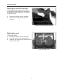
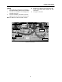
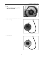
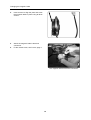
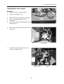
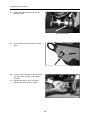
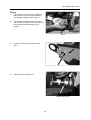
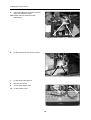
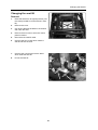
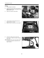
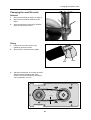
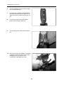
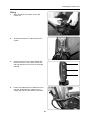
SERVICE MANUAL
Chairman Basic
Chassinr. 400 001-
US
Contents
Introduction .....................................................................................................3
Technical support.........................................................................................3
Spare parts ..................................................................................................3
Warranties....................................................................................................3
Maintenance ................................................................................................3
Rating plates ...................................................................................................4
Chairman Basic ...........................................................................................4
Control unit ..................................................................................................4
Raising the seat lift.........................................................................................5
Covers..............................................................................................................6
Removal.......................................................................................................6
Fitting ...........................................................................................................6
Changing the batteries...................................................................................7
Removal.......................................................................................................7
Fitting ...........................................................................................................8
Changing the drive wheel ..............................................................................9
Removal.......................................................................................................9
Fitting ...........................................................................................................9
Changing the brake release wires ................................................................10
Changing the magnetic brake .......................................................................11
Removal.......................................................................................................11
Fitting ...........................................................................................................12
Changing the drive motor..............................................................................14
Removal.......................................................................................................14
Fitting ...........................................................................................................16
Changing the carbon-brush in the drive motor...........................................18
Removal of the carbon-brush ......................................................................18
Fitting the carbon-brush...............................................................................19
Changing the seat lift .....................................................................................20
Removal.......................................................................................................20
Fitting ...........................................................................................................21
Changing the seat lift motor..........................................................................22
Removal.......................................................................................................22
Fitting ...........................................................................................................22
Seat lift belt .....................................................................................................23
Changing the seat lift belt............................................................................23
Changing the control unit..............................................................................24
Removal.......................................................................................................24
Fitting ...........................................................................................................26
Fault codes......................................................................................................29
Wiring diagram................................................................................................30
3
Introduction
Introduction
The Service Manual is intended for technical personnel who maintain and repair electric wheelchairs.
It is important that anyone who performs maintenance and repairs described in this manual reads and
understands the content of this manual so that the work is performed professionally. Always state the
chassis number when contacting Permobil to ensure that the correct information is provided.
Technical Support
In the event of Technical Problems, you should contact your dealer, or Pemobil Inc at 800-736-0925
Spare parts
Spare parts must be ordered through your dealer.
The spare parts catalogue for the Chairman Basic chassis is PAB 1224 and is available from Permobil
Inc.
Warranties
The Warranty Manual, PAB 9533, contains information on the current warranties available from
Permobil AB. Warranties for the Swedish market are covered by a supply contract with SUB.
Equivalent contracts for other markets are available from Permobil.
Maintenance
See the information in the Instructions for Use.
Reconditioning
Reconditioning instructions are available from Permobil.
Produced and published by Permobil AB, Sweden
Edition no. 1, Jan 1999
Order no: 201064-US-0
PAB nr: 1064:1
4
Rating plates
Rating plates
Chairman Basic
Identity marking
Chassis no.
Control unit/
panel
Identity marking
Art. no.
Serial no.
Modification no.
5
Raising the seat lift
Raising the seat lift manually
If the seat lift cannot be raised in the normal
manner because the batteries are discharged or
the adjustment device is defective, the seat can
be raised manually.
1.
2.
Remove the cushion and the seat plate.
Raise the seat using the seat lift crank
provided.
Raise the seat with the seat lift crank
Raising the seat
(Fixed seat tube)
1.
2.
3.
Remove the cushion and the seat plate.
Loosen the screw for the seat tube brace.
Raise the seat using the seat lift crank or pull
the seat up by hand.
Seat tube brace screw
6
Cover
Cover
Removal
1.
2.
3.
Raise the seat to its highest position.
Loosen the three plastic knobs which hold
the cover in place.
Remove the cover.
Fitting
1.
2.
Place the cover on the chassis.
Tighten the three plastic knobs which hold
the cover in place.
7
Changing the batteries
Changing the batteries
NB. Use protective goggles when working with
batteries.
Removal
1.
2.
3.
4.
Raise the seat to its highest position. If the
battery is defective, see Raising the seat lift
on page 6.
Remove the chassis cover. It is held in place
by three plastic knobs.
Disconnect all battery connections, the
positive poles first and then the negative
poles.
Lift out the batteries. Use lifting straps.
8
Changing the batteries
4.
Fitting
1.
If the wheelchair is fitted with acid batteries,
check that the battery fluid is at the right level.
2. Insert two new batteries. The battery poles
must be at the front.
3. Connect the battery connections, first the
negative poles and then the positive poles.
NB! The cables must be connected correctly.
Main fuse
5.
Replace the chassis cover and set the seat
to the correct height again. Tighten the seat
tube brace.
Charge the batteries.
Black cable from main fuse
Red cable from main fuse
Front
Black cable = Bat -
+ –
–
Red cable - Bat +
+
Black cable - Bat -
Rear
Red cable - Bat +
Battery connections
9
Changing the drive wheel
Changing the drive wheel
Removal
1.
2.
3.
Raise and block up the wheelchair's chassis
so that the wheel does not reach the
ground.
Loosen and remove the centre screw C, the
washer B and the rim locking washer A (see
the figure at the bottom of the page).
Pull the wheel off the axle. Use the removal
tool 304103-99-0 if the wheel cannot be
removed by hand.
Removal tool 304103-99-0
Fitting
1.
2.
Fit the wheel onto the axle.
Fit the rim locking washer A, the washer B
and the centre screw C and tighten to
secure the wheel.
NB! The screw has a locking coating which is
sufficient for refitting 3-4 times. Then the screw
must be replaced with a new one.
10
Changing the brake release wires
1
2
Brake release mechanism
Changing the brake release wires Fitting
The upper wire controls the left brake unit and the
lower wire controls the right brake unit.
1.
Fit the wire first at the magnetic brake and
then at the release lever.
2.
Adjust the length of the wire sleeve using
the adjusting screw (2) so that the wire is
tensioned but does not pull on the release
clamp.
3.
Check that the brake works. Release the
brake with the release lever and check that
the wheel can turn.
4.
Refit the cover.
Removal
1.
2.
Raise the seat lift to its highest position (use
the crank provided for chairs without a seat
lift).
Remove the cover. Move the brake release
lever forwards to its front position to facilitate
removal.
3.
Loosen the locking nut (1).
4.
Screw the adjusting screw (2) all the way in.
5.
Loosen the wire at the magnetic brake and
at the brake release mechanism.
11
Changing the magnetic brake
Changing the magnetic brake
Removal
1.
2.
3.
Raise the seat to its highest position.
Remove the chassis cover, which is held in
place by three plastic knobs.
Loosen the electrical connection of the
magnetic brake.
Electrical connection of the magnetic brake
4.
Detach the brake release wire from the
brake.
5.
Unscrew the three screws which hold the
brake and remove the brake with the
extensible cover, brake disc and cover.
Note the position of the brake release arm.
6.
12
Changing the magnetic brake
Fitting
1.
Check the setting of the brake. Follow the
instructions on the decal on how the two
Allen screws are adjusted.
2.
Place the magnetic brake's brake disc in the
brake assembly.
3.
Put on the cover.
13
Changing the magnetic brake
4.
Insert a screw to align the parts and screw
the magnetic brake in place using all three
screws.
5.
Attach the magnetic brake's electrical
connection.
Fit the chassis cover, see Covers, page 7.
6.
The magnetic brake's electrical connection
14
Changing the drive motor
Changing the drive motor
Removal
1.
2.
Raise the seat to its highest position.
Remove the chassis cover.
3.
4.
Remove the positive pole from one battery.
Block up the appropriate side of the
wheelchair.
Remove the wheel. See Changing the drive
wheel, page 10.
5.
6.
Remove the two screws for the fuse holder
(left motor).
Fuse holder
7
Detach the electrical connections for the
motor and magnetic brake.
Magnetic brake
15
Motor
Changing the drive motor
8.
Detach the brake release wire from the
magnetic brake.
Brake release wire
9.
Remove the three screws which hold the
motor.
10. Turn the motor sideways so that the wheel
axle turns freely. Pull the motor straight
forwards.
11. Remove the spacer, which is located
between the motor and the chassis.
16
Changing the drive motor
Fitting
1.
If a new motor is to be fitted, the magnetic
brake must be moved from the old motor.
See Fitting a magnetic brake, page 13.
2.
Fit the spacer and lift the motor into place.
Turn it a little so that the wheel axle can turn
freely without being obstructed by the
chassis.
Spacer
3.
Screw the motor in place with the three
bolts.
4.
Attach the brake release wire.
Brake release wire
17
Changing the drive motor
5.
Attach the electrical connections for the
motor and magnetic brake.
NB. Ensure that the contacts are fully
interlocking.n
Magnetic brake contact
6.
Fit the fuse holder with the two screws.
7.
Fit the wheel. See page 10.
8.
Remove the blocks.
9.
Connect the battery poles.
10. Fit the chassis cover.
18
Motor contact
Changing the carbon-brush in the drive motor
Changing the carbon-brush
in the drive motor
Removal
1.
2.
Remove the drive motor. See page 15.
Remove the motor's cables from the
coupling box.
3.
Remove the magnetic brake and the
mounting plate.
Mark the stator's position against both ends
with a small mark before loosening the nuts.
It is important for the function of the motor
that the parts are assembled precisely
without being moved away from the original
position.
Loosen two nuts and pull off the motor end.
Press the cable gland off the motor end.
4.
5.
6.
Remove the brush holder completely.
Do not
divide here
Marking
19
Changing the carbon-brush in the drive motor
Fitting
1.
Fit a new carbon-brush using the fitting ring
provided with the new brush holder. Ensure
that you turn the cables in the same
direction as the outgoing shaft of the gear.
2.
Fit the end with two nuts.
Remember the wave washer between the
bearing and the end. Ensure that you
assemble the parts according to the marking
made earlier.
It is important for the function of the motor
that the parts are assembled precisely
without being moved away from the original
position.
3.
4.
5.
Marking
Insert the mounting plate, cover and brake
disc. Ensure that you position the holes
correctly for fitting the brake.
Turn the brake so that the brake arm is in
the correct position. Turn the holes in the
extensible cover downwards so that any
condensation water can run out.
Screw the motor cables to the coupling box.
Fit the drive motor. See page 17.
20
Changing the seat lift
Changing the seat lift
Removal
1.
Raise the seat lift to its highest position (use
the crank provided for chairs without a seat
lift).
2.
Remove the cover.
3.
Cut off the cable ties located on the seat lift
and under the seat.
4.
Remove the arm rest on which the control
panel is located.
5.
Disconnect the seat lift cable.
6.
Unscrew the four screws which hold the
seat and lift out the seat.
7.
Unscrew the nuts and remove the brace
which holds the seat lift.
8.
Lift out the seat lift.
21
Changing the seat lift
Fitting
1.
Lift and replace the seat lift.
2.
Replace the yoke and secure the seat lift by
tightening the four nuts. The screws must be
tightened with 24 Nm.
3.
Attach the contacts to the seat lift.
4.
Lift and replace the seat and secure it by
tightening the four screws.
5.
Replace the arm rest with the control panel.
6.
Fasten the cables with new cable ties.
Check that no cables are caught or folded in
sharp folds.
NB! The radius of the curve of the cable must be
at least 80 mm when the seat lift is in its
highest position.
80 mm
22
Changing the seat lift motor
Changing the seat lift motor
Removal
1.
Remove the seat lift as shown on page 21.
2.
Disconnect the seat lift cables from the
motor.
3.
Unscrew the three screws which hold the
motor and remove the motor.
Fitting
1.
Fit the new motor and secure it by
tightening the three screws.
2.
Reconnect the seat lift motor's cables.
Blue
3.
Adjust the belt tension by moving the motor
sideways before tightening the motor
screws. The belt is sufficiently taut when it
can be pressed in 4-5 mm.
4-5 mm
23
Green
Changing the seat lift belt
Changing the seat lift belt
1.
Remove the seat lift. See page 21.
2.
Loosen the four screws which hold the seat
lift motor. Move the motor sideways so that
the belt becomes slack.
3.
Remove the belt first from the motor and
then from the cog wheel on the seat lift
screw.
4.
Change the belt and reassemble in the
reverse order.
5.
Adjust the belt tension by moving the motor
sideways. The belt is sufficiently taut when it
can be pressed in 4-5 mm.
6.
Tighten the four screws again.
7.
Fit the seat lift. See page 22.
4-5 mm
24
Changing the control unit
Changing the control unit
Removal
1.
2.
3.
Raise the seat to its highest position.
Remove the chassis cover.
Remove the poles from the battery. Start
with the positive poles.
4.
Detach the two cable connections on the
right side.
5.
Detach the three cable connections on the
left side.
25
Changing the control unit
6.
Cut off the cable ties which hold the cables
in the chassis and seat.
7.
If the seat has a seat lift or seat inclination,
the cable ties which hold the cables for the
button box and the control unit must be cut
off.
8.
Unscrew the three screws in the panel
holder which hold the control unit.
9.
Unscrew the screws which hold the button
box.
10. Remove the button box holder by squeezing
it together so that the hooks on each side
disengage. You may need to use a
screwdriver to disengage the hooks.
26
Changing the control unit
Fitting
1.
Place the button box holder on the new
control unit.
2.
Screw the button box in place with the two
screws.
3.
Fit the control unit on the panel holder with
the three screws. Fit the centre screw first
and then adjust the control unit to the angle
required.
4.
Fasten the cables with four cable ties on the
arm rest. Ensure that the cables are not
caught and that they are folded in soft folds.
27
Changing the control unit
5.
Fasten the cables under the chair and
around the base of the seat lift using cable
ties.
NB! The radius of the curve of the cable
must be at least 80 mm when the seat lift is
in its highest position.
80 mm
6.
Connect the connections on the right side (2
contacts). See the marking on the cables.
NB! Ensure that the contacts go all the way
in.
7.
Connect the connections on the left side (3
contacts). See the marking on the cables..
NB! Ensure that the contacts go all the way
in.
8.
Reconnect the contacts to the battery.
Main fuse
Red cable from
main fuse
9.
Black cable from main fuse
Replace the chassis cover.
Front
Black cable = Bat -
+ –
–
Rear
Red cable - Bat +
+
Black cable - Bat -
Red cable - Bat +
28
Battery indicator
- Battery indicator flashes fast.
A fault has occurred and the wheelchair will not
work. The number of flashing lights indicates the
nature of the fault.
- Note the number of flashing lights.
- Switch off the wheelchair.
- Switch the wheelchair back on.
- Check whether the fault is still present.
Battery indicator
The battery indicator indicates the status of the
wheelchair.
- Battery indicator lights permanently
This indicates that everything is OK.
- Battery indicator flashes slowly.
This indicates that the battery should be
charged as soon as possible.
Troubleshooting
If a fault occurs in the wheelchair, a number of lights flash on the battery voltage indicator. Count the number
of lights, starting from the joystick, and check in the list what the fault is and what you can do.
Number
of lights
Cause
Remedy
1
The charge level of the battery is
much too low. It requires
immediate charging
Check the condition of the battery to see whether it
needs replacing.
Check the contact between the battery and the
control unit.
2
There is an interruption to the left
motor.
Check the connection to the left drive motor.
Check whether the drive motor's carbon-brush is
worn.
3
Short-circuit between the battery
and the drive motor.
Check the contacts and cables of the motor.
4
There is an interruption to the right
motor.
Check the connection to the right drive motor.
Check whether the drive motor's carbon-brush is
worn.
5
Short-circuit between the battery
and the drive motor.
Check the contacts and cables of the motor.
6
Charger connected to charging
socket.
Remove the charging contact from the chair.
7
Joystick fault.
Ensure that the joystick is not affected by
operation. If the fault is still present, replace the
control unit.
8
Control unit fault.
Check the contacts of the control unit.
If the fault is still present, replace the control unit.
9
Interruption in brake circuit.
Check the contacts of the magnetic brake.
10
Too high voltage in the battery
Check the battery and the contacts between the
battery and the control unit.
29
CABEL FUSE KIT 8391-1
MEMBRANSWITCH 6061-3
MEMBRANSWITCH ACTUATOR CONTROLLER 5954-10
CABEL SWITCHBOX 5547
Wiring diagram
Permobil INC. USA
6961 Eastgate Blvd. Lebanon, TN 37090 USA Phone: 800-736-0925 Fax: 800-231-3256