1
Myostat
CM1 Modbus User Manual
Version: 1.0.3
02-Dec-2014 10:14
Date:
Table of Contents
1
1.1
1.2
2
2.1
2.2
Getting Started
3
Introduction
1.1.1
Modbus TCP
3
3
1.1.2
3
Modbus RTU
Modbus Registers and Usage
4
Configuring Modbus
5
Configuring Modbus RTU
2.1.1
Requirements
5
5
2.1.2
5
Set to Modbus RTU
Configuring Modbus TCP
2.2.1
Requirements
7
7
2.2.2
7
Configure Network Settings
3
Read/Write Access Table
15
4
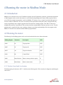
Running the motor in Modbus Mode
30
4.1
4.2
4.3
Introduction
30
Running the motor
4.2.1
Position, Speed and Acceleration
30
30
4.2.2
31
Control Word
CML Code
32
CM1 Modbus User Manual
1 Getting Started
1.1 Introduction
Modbus on the CM1 can be implemented over Modbus RTU or Modbus TCP. The main motor remains the same over
both variants but require different interface modules. Modbus is not available on motors with firmware RT3.12 but
requires versions RT3.13 or higher.
1.1.1 Modbus TCP
Modbus TCP requires the Modbus Ethernet module and has the following part numbers for the 4 motor options.
Part Number
Description
CM1-C-17S30-MBT
NEMA 17 single stack CM1 Cool Muscle motor with Modbus TCP
CM1-C-17L30-MBT
NEMA 17 double stack CM1 Cool Muscle motor with Modbus TCP*
CM1-C-23S30-MBT
NEMA 23 single stack CM1 Cool Muscle motor with Modbus TCP*
CM1-C-23L20-MBT
NEMA 23 double stack CM1 Cool Muscle motor with Modbus TCP*
*For torque and speed characteristics please see the CM1 data sheet.
1.1.2 Modbus RTU
Modbus RTU is available on the standard motor as it uses serial as its communication protocol. The standard motor
can then be coupled with different interface modules (-SRLM, -SRLS, -EIO) to allow for a wider range of connectivity
to a PLC, HMI, PC or embedded controller. It can be ordered with standard motor part numbers but should include the
firmware version to ensure the correct version is ordered.
Part Number
Description
CM1-C-11S30-RT3.13
NEMA 11 single stack CM1 Cool Muscle motor**
CM1-C-11L30-RT3.13
NEMA 11 double stack CM1 Cool Muscle motor**
CM1-C-17S30-RT3.13
NEMA 17 single stack CM1 Cool Muscle motor with Modbus RTU*
www.myostat.ca
3 of 34
CM1 Modbus User Manual
Part Number
Description
CM1-C-17L30-RT3.13
NEMA 17 double stack CM1 Cool Muscle motor with Modbus RTU*
CM1-C-23S30-RT3.13
NEMA 23 single stack CM1 Cool Muscle motor with Modbus RTU*
CM1-C-23L30-RT3.13
NEMA 23 double stack CM1 Cool Muscle motor with Modbus RTU*
*For torque and speed characteristics please see the CM1 data sheet.
**The 11L and 11S motors have a different packaging and additional interface modules cannot be mounted and
integrated directly onto the motor.
1.2 Modbus Registers and Usage
All motor parameters are available in read/write access through Modbus holding registers. All registers are 32bit little
endian registers. CML code is required in the motor to execute a move. All Modbus TCP motors have a generic
point-to-point program written in the motor and this can be modfied to suit the application. As Modbus RTU is a user
select-able option it does not come preloaded, however, the program is shown and described further in this
documentation and can easily be loaded onto the motor.
The supplied program contains 4 main write variables.
1. Position (P0 register)
2. Speed (S0 register)
3. Acceleration (A0 register)
4. Control Word (R0 register)
The control word allows the user to start, stop, home, enable and disable the motor. Starting the motor will run the
motor to the defined position, speed and acceleration. Position feedback, speed and motor status are available for read
through the relevant registers. Please see the supplied code example for a complete description.
www.myostat.ca
4 of 34
CM1 Modbus User Manual
2 Configuring Modbus
2.1 Configuring Modbus RTU
2.1.1 Requirements
To switch the motor into Modbus RTU you will need the following
1. CM1 motor with RT3.13 firmware (Send "?85" to query the version if you are not sure)
2. Control Room (which can be found here)
3. Communication to the motor from the PC running Control Room. This can be achieved with a number of cables
and/or interfaces.
a. If you are unsure of how to communicate with the motor please see the quick start guide.
2.1.2 Set to Modbus RTU
Once the motor is connected and communicating with Control Room it can be switched from standard ascii
communication to Modbus RTU. The following parameters are used to make the change. Read through the descriptions
of them and then follow the step-by-step instructions
K20 - COM1 Communication Baud Rate
K20 sets the communication baud rate between the Modbus master and the motor. Using the standard baud rate setting
+10 will switch it to Modbus mode with that baud rate
K20 Value
Baudrate (bps)
K20=10
38400
K20=11
9600
K20=12
19200
K20=13
57600
The motor default baudrate is 38400.
www.myostat.ca
5 of 34
CM1 Modbus User Manual
K62 - Modbus station ID
K62 sets the Modbus station ID. This ID is also used for the RS485 protocol. If the motor starts streaming { with the
ID that has been set then it is in RS485 (the software protocol) mode. See this Application Note to switch out of RS485
mode.
K65 - COM2 Communication Baud Rate
COM2 on the motor can be used for Modbus communication. This is not typically used and requires a special cable. If
you need to use COM1 for standard communication and COM2 for Modbus communication please contact a Myostat
engineer for assistance.
FFFFFFFFF - 9 x Fs function
"FFFFFFFFF" (9xF) is used to temporarily switch the motor out of Modbus mode. This will allow you, until a power
cycle, to communicate with the motor using standard ASCII and regular CML. To switch back into Modbus the motor
will need to be power cycled or K20 set to normal ASCII and then back to Modbus.
Step-By-Step Guide
Use the following steps to set a motor into Modbus mode. In this example we are setting the motor to ID=1 with a baud
rate of 38400bps.
1. Set the motor into modbus mode with a baud rate = 38400
K20=10
2. Send 9 x F to get out of Modbus mode
FFFFFFFFF
3. Set the station ID to 1
K62=1
4. Cycle power on the motor.
The motor is now in Modbus RTU mode and can be communicated with a Modbus master.
www.myostat.ca
6 of 34
CM1 Modbus User Manual
2.2 Configuring Modbus TCP
The user will want to setup the network settings for the Modbus TCP motor. This could include setting a static/
dynamic IP and/or a password.
2.2.1 Requirements
To configure a CM1 with Modbus TCP you should have the following
1. CM1 motor with -MBT module (e.g. CM1-C-23L20-MBT)
2. Control Room (which can be found here)
2.2.2 Configure Network Settings
Two main network settings can be changed
1. Static or dynamic (default) IP address
2. Network password
When you logon to the Modbus TCP web configuration page there are other Modbus related settings. These should be
left as they are. If you reset the module to defaults please refer to the Configuring Modbus section at the bottom of this
page.
Logon to the Configuration page
When logging onto the configuration page for the first time there is no password. Follow the steps below to logon.
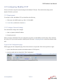
1. Open Control Room and search for the module under the TCP/IP options
2. Once the module has been found click "Web Configuration"
www.myostat.ca
7 of 34
CM1 Modbus User Manual
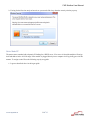
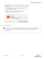
3. If using for the first time and you haven't set a password click okay when the security window pops up.
Set to Static IP
The motor comes standard with a dynamic IP looking for a DHCP server. If no server is found the module will assign
itself and address in the 169.254 range. If the module is plugged directly into a computer it will typically get set in this
manner. To assign a static IP use the following step-by-step guide.
1. Logon as described above in the logon guide
www.myostat.ca
8 of 34
CM1 Modbus User Manual
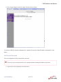
2. Click "Network" in the left panel to open up the Network settings
a. Select "Use the following IP configuration" and set your required network settings
b. Click the OK button
www.myostat.ca
9 of 34
CM1 Modbus User Manual
3. Click "Apply Settings" in the left column. The unit will now reboot.
To set back to DHCP or another configuration for a dynamic IP select the "Obtain IP address automatically" radio
button.
Set Network Password
The web configuration can be protected with a password.
There is no way to reset the password if it is forgotten without returning the module to the factory.
1. Logon to the web configuration as described above
www.myostat.ca
10 of 34
CM1 Modbus User Manual
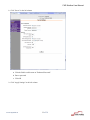
2. Click "Server" in the left column
a. Click the Enable radio button on "Enhanced Password"
b. Enter a password
c. Click OK
3. Click "Apply Settings" in the left column.
www.myostat.ca
11 of 34
CM1 Modbus User Manual
4. The module will reboot. To login again use the password that has just been set.
Configuring Modbus
This section is relevant if a user has clicked "Apply Defaults" on the web interface. The module will have
arrived with the correct Modbus TCP settings. Do not change Modbus settings unless instructed to my a
Myostat engineer.
www.myostat.ca
12 of 34
CM1 Modbus User Manual
1. Click "Serial Settings"
a. changed the Baud Rate to 38400
b. Click OK
www.myostat.ca
13 of 34
CM1 Modbus User Manual
2. Select "Modbus/TCP"
a. Change "Fixed Slave Address" to 1
b. Click Okay
3. Click "Apply Settings"
The Modbus TCP module has now been set to correctly communicate with the motor.
www.myostat.ca
14 of 34
CM1 Modbus User Manual
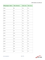
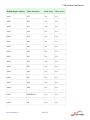
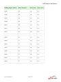
3 Read/Write Access Table
Included below is a table which details the location and function of the CM1 Modbus registers.
The addresses included below are referenced to the Modbus data model (PLC address for read/write to holding
registers)
Click on a link below to jump to the associated registers
1. Motor Information Registers
2. Variables
3. Direct Registers
4. IO
5. CML Port
6. Positions
7. R Registers
8. N Registers
9. Speeds
10. Accelerations
11. Torque
12. K Parameters
13. H Gain Parameters
14. Timers
Holding Register Address
Motor Parameter
Read Access
Write Access
40001
Position Error (?95)
Yes
No
40003
Motor Position (?96)
Yes
No
40005
Motor Speed (?97)
Yes
No
40007
Motor Torque (?98)
Yes
No
40009
Motor Status (?99)
Yes
No
www.myostat.ca
15 of 34
CM1 Modbus User Manual
Holding Register Address
Motor Parameter
Read Access
Write Access
40011
V0
Yes
Yes
40013
V1
Yes
Yes
40015
V2
Yes
Yes
40017
V3
Yes
Yes
40019
V4
Yes
Yes
40021
V5
Yes
Yes
40023
V6
Yes
Yes
40025
V7
Yes
Yes
40027
V8
Yes
Yes
40029
V9
Yes
Yes
40031
V10
Yes
Yes
40033
V11
Yes
Yes
40035
V12
Yes
Yes
40037
V13
Yes
Yes
40039
V14
Yes
Yes
40041
V15
Yes
Yes
40043
P0
Yes
Yes
www.myostat.ca
16 of 34
CM1 Modbus User Manual
Holding Register Address
Motor Parameter
Read Access
Write Access
40045
S0
Yes
Yes
40047
A0
Yes
Yes
40049
V0
Yes
Yes
40051
R0
Yes
Yes
40053
M0
Yes
Yes
40055
Analog Output
Yes
Yes
40057
Input Status (?70)
Yes
No
40059
Output Status (?50)
Yes
Yes
40103
CML Port [ASCII]
No
Yes
40201
P0
Yes
Yes
40203
P1
Yes
Yes
40205
P2
Yes
Yes
40207
P3
Yes
Yes
40209
P4
Yes
Yes
40211
P5
Yes
Yes
40213
P6
Yes
Yes
40215
P7
Yes
Yes
www.myostat.ca
17 of 34
CM1 Modbus User Manual
Holding Register Address
Motor Parameter
Read Access
Write Access
40217
P8
Yes
Yes
40219
P9
Yes
Yes
40221
P10
Yes
Yes
40223
P11
Yes
Yes
40225
P12
Yes
Yes
40227
P13
Yes
Yes
40229
P14
Yes
Yes
40231
P15
Yes
Yes
40233
P16
Yes
Yes
40235
P17
Yes
Yes
40237
P18
Yes
Yes
40239
P19
Yes
Yes
40241
P20
Yes
Yes
40243
P21
Yes
Yes
40245
P22
Yes
Yes
40247
P23
Yes
Yes
40249
P24
Yes
Yes
40251
P25
Yes
Yes
www.myostat.ca
18 of 34
CM1 Modbus User Manual
Holding Register Address
Motor Parameter
Read Access
Write Access
40301
R0
Yes
Yes
40303
R1
Yes
Yes
40305
R2
Yes
Yes
40307
R3
Yes
Yes
40309
R4
Yes
Yes
40311
R5
Yes
Yes
40313
R6
Yes
Yes
40315
R7
Yes
Yes
40317
P8
Yes
Yes
40319
P9
Yes
Yes
40321
R10
Yes
Yes
40323
R11
Yes
Yes
40325
R12
Yes
Yes
40327
R13
Yes
Yes
40329
R14
Yes
Yes
40331
R15
Yes
Yes
40333
R16
Yes
Yes
40335
R17
Yes
Yes
www.myostat.ca
19 of 34
CM1 Modbus User Manual
Holding Register Address
Motor Parameter
Read Access
Write Access
40337
R18
Yes
Yes
40339
R19
Yes
Yes
40341
R20
Yes
Yes
40343
R21
Yes
Yes
40345
R22
Yes
Yes
40347
R23
Yes
Yes
40349
R24
Yes
Yes
40351
R25
Yes
Yes
40401
N0
Yes
Yes
40403
N1
Yes
Yes
40405
N2
Yes
Yes
40407
N3
Yes
Yes
40409
N4
Yes
Yes
40411
N5
Yes
Yes
40413
N6
Yes
Yes
40415
N7
Yes
Yes
40417
N8
Yes
Yes
40419
N9
Yes
Yes
www.myostat.ca
20 of 34
CM1 Modbus User Manual
Holding Register Address
Motor Parameter
Read Access
Write Access
40421
N10
Yes
Yes
40423
N11
Yes
Yes
40425
N12
Yes
Yes
40427
N13
Yes
Yes
40429
N14
Yes
Yes
40431
N15
Yes
Yes
40433
N16
Yes
Yes
40435
N17
Yes
Yes
40437
N18
Yes
Yes
40439
N19
Yes
Yes
40441
N20
Yes
Yes
40443
N21
Yes
Yes
40445
N22
Yes
Yes
40447
N23
Yes
Yes
40449
N24
Yes
Yes
40451
N25
Yes
Yes
40603
S0
Yes
Yes
40605
S1
Yes
Yes
www.myostat.ca
21 of 34
CM1 Modbus User Manual
Holding Register Address
Motor Parameter
Read Access
Write Access
40607
S2
Yes
Yes
40609
S3
Yes
Yes
40611
S4
Yes
Yes
40613
S5
Yes
Yes
40615
S6
Yes
Yes
40617
S7
Yes
Yes
40619
S8
Yes
Yes
40621
S9
Yes
Yes
40623
S10
Yes
Yes
40625
S11
Yes
Yes
40627
S12
Yes
Yes
40629
S13
Yes
Yes
40631
S14
Yes
Yes
40633
S15
Yes
Yes
40635
A0
Yes
Yes
40637
A1
Yes
Yes
40639
A2
Yes
Yes
40641
A3
Yes
Yes
www.myostat.ca
22 of 34
CM1 Modbus User Manual
Holding Register Address
Motor Parameter
Read Access
Write Access
40643
A4
Yes
Yes
40645
A5
Yes
Yes
40647
A6
Yes
Yes
40649
A7
Yes
Yes
40651
A8
Yes
Yes
40653
M0
Yes
Yes
40655
M1
Yes
Yes
40657
M2
Yes
Yes
40659
M3
Yes
Yes
40661
M4
Yes
Yes
40663
M5
Yes
Yes
40665
M6
Yes
Yes
40667
M7
Yes
Yes
40669
M8
Yes
Yes
40671
K0
Yes
Yes
40673
K1
Yes
Yes
40675
K2
Yes
Yes
www.myostat.ca
23 of 34
CM1 Modbus User Manual
Holding Register Address
Motor Parameter
Read Access
Write Access
40677
K3
Yes
Yes
40679
K4
Yes
Yes
40681
K5
Yes
Yes
40683
K6
Yes
Yes
40685
K7
Yes
Yes
40687
K8
Yes
Yes
40689
K9
Yes
Yes
40691
K10
Yes
Yes
40693
K11
Yes
Yes
40695
K12
Yes
Yes
40697
K13
Yes
Yes
40699
K14
Yes
Yes
40701
K15
Yes
Yes
40703
K16
Yes
Yes
40705
K17
Yes
Yes
40707
K18
Yes
Yes
40709
K19
Yes
Yes
40711
K20
Yes
Yes
www.myostat.ca
24 of 34
CM1 Modbus User Manual
Holding Register Address
Motor Parameter
Read Access
Write Access
40713
K21
Yes
Yes
40715
K22
Yes
Yes
40717
K23
Yes
Yes
40719
K24
Yes
Yes
40721
K25
Yes
Yes
40723
K26
Yes
Yes
40725
K27
Yes
Yes
40727
K28
Yes
Yes
40729
K29
Yes
Yes
40731
K30
Yes
Yes
40733
K31
Yes
Yes
40735
K32
Yes
Yes
40737
K33
Yes
Yes
40739
K34
Yes
Yes
40741
K35
Yes
Yes
40743
K36
Yes
Yes
40745
K37
Yes
Yes
40747
K38
Yes
Yes
www.myostat.ca
25 of 34
CM1 Modbus User Manual
Holding Register Address
Motor Parameter
Read Access
Write Access
40749
K39
Yes
Yes
40751
K40
Yes
Yes
40753
K41
Yes
Yes
40755
K42
Yes
Yes
40757
K43
Yes
Yes
40759
K44
Yes
Yes
40761
K45
Yes
Yes
40763
K46
Yes
Yes
40765
K47
Yes
Yes
40767
K48
Yes
Yes
40769
K49
Yes
Yes
40771
K50
Yes
Yes
40773
K51
Yes
Yes
40775
K52
Yes
Yes
40777
K53
Yes
Yes
40779
K54
Yes
Yes
40781
K55
Yes
Yes
40783
K56
Yes
Yes
www.myostat.ca
26 of 34
CM1 Modbus User Manual
Holding Register Address
Motor Parameter
Read Access
Write Access
40785
K57
Yes
Yes
40787
K58
Yes
Yes
40789
K59
Yes
Yes
40791
K60
Yes
Yes
40793
K61
Yes
Yes
40795
K62
Yes
Yes
40797
K63
Yes
Yes
40799
K64
Yes
Yes
40801
K65
Yes
Yes
40803
K66
Yes
Yes
40805
K67
Yes
Yes
40807
K68
Yes
Yes
40809
K69
Yes
Yes
40811
K70
Yes
Yes
40813
K71
Yes
Yes
40815
K72
Yes
Yes
40817
K73
Yes
Yes
40819
K74
Yes
Yes
www.myostat.ca
27 of 34
CM1 Modbus User Manual
Holding Register Address
Motor Parameter
Read Access
Write Access
40821
K75
Yes
Yes
40823
K76
Yes
Yes
40825
K77
Yes
Yes
40827
K78
Yes
Yes
40829
K79
Yes
Yes
40831
K80
Yes
Yes
40833
K81
Yes
Yes
40835
K82
Yes
Yes
40837
K83
Yes
Yes
40839
K84
Yes
Yes
40841
K85
Yes
Yes
40843
K86
Yes
Yes
40845
K87
Yes
Yes
40847
K88
Yes
Yes
40849
K89
Yes
Yes
40875
RESERVED
Yes
Yes
40901
H0
Yes
Yes
www.myostat.ca
28 of 34
CM1 Modbus User Manual
Holding Register Address
Motor Parameter
Read Access
Write Access
40903
H1
Yes
Yes
40905
H2
Yes
Yes
40907
H3
Yes
Yes
40909
H4
Yes
Yes
40911
H5
Yes
Yes
40913
H6
Yes
Yes
40915
H7
Yes
Yes
40951
T0
Yes
No
40953
T1
Yes
Yes
40955
T2
Yes
Yes
40957
T3
Yes
Yes
40959
T4
Yes
Yes
40951
T5
Yes
Yes
40953
T6
Yes
Yes
40955
T7
Yes
Yes
www.myostat.ca
29 of 34
CM1 Modbus User Manual
4 Running the motor in Modbus Mode
4.1 Introduction
Modbus gives read/write access to all Cool Muscle registers such as K-parameters, positions, speeds and accelerations.
A CML program needs to reside in the motor to execute functions depending on the status of these registers. Below
you will find an example program that is used in all Modbus TCP motors. It uses a control word in the R0 register to
execute a number of functions. This code is useful for point-to-point motion and speed control. An application may
require a significantly more complex program which can replace the example program. The CML is written to be
compiled and sent from Control Room. The user does not need to understand the code but only how to use it. The full
program code is supplied for those users wanting to change or get a better understanding of how the program works.
Modbus TCP motors come standard with the Modbus program loaded.
4.2 Running the motor
The following list of holding registers can be used to the read and write move data to the motor.
Holding Register
Parameter
Description
R/W
40201
P0
Target position
R/W
40603
S0
Target speed
R/W
40635
A0
Target acceleration
R/W
40301
R0
Control Word
R/W
40003
Motor Position
Motors current position in pulses
R
40009
Motor Status
Motors current status
R
4.2.1 Position, Speed and Acceleration
The default setting for the motor is K37=3 which sets the following units. This can easily be changed by modifying the
value of K37.
www.myostat.ca
30 of 34
CM1 Modbus User Manual
Register
Unit/Resolution
P0
1000 pulses/revolution
S0
100 pulse/s
A0
1K pulses/s2
4.2.2 Control Word
The R1 register is used for the Control Word. It has the following value options
R0 Value
Description
0
Do nothing
1
Start the position move
2
Stop the motor
3
Enable the motor
4
Disable the motor
5
Home the motor
Some things to note when using the control word
1. Changing the value of the control word immediately executes the operation
2. If the Control Word is left with the value 1 then changing the position once the motor has come to a stop will
execute the next move. This allows the Modbus master to only change the position and not need to also toggle
the control word to execute the next move.
3. The home routine is by default set to a hardstop search in the CCW direction. Please see K42 to K48 for home
routine options.
www.myostat.ca
31 of 34
CM1 Modbus User Manual
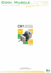
4.3 CML Code
The following is the CML code used for motor control in Modbus. It is not required for users to understand the code
unless they are looking to change it.
CML Modbus Code
//set the logic scan rate to 1ms
K87.1=1
//set logic bank 1 to scan on power up
K85.1=1
//set the modbus register offset to 0
K89.1=0
//switch off all automatic motor event reporting
K23.1=0
//make sure carraige return is not automatic after line feed (legacy
setting)
K70.1=0
/*create variables for the old/previous target
control word
position
speed
acceleration
These are used to find a change in the target
Init them to 0
*/
var old_ControlWord R1.1
//old control word
R1.1=0
var old_TargetPos P1.1
//old position
P1.1=0
var old_TargetSpd S1.1
//old speed
S1.1=0
var old_TargetAcc A1.1
//old acceleration
A1.1=0
/*create variables for the new target
control word
position
speed
acceleration
These are used to find a change in the target
Init them to 0
*/
var ControlWord R0.1
//control word
R0.1=0
var TargetPos P0.1
//position
P0.1=0
www.myostat.ca
32 of 34
CM1 Modbus User Manual
var TargetSpd S0.1
//speed
S0.1=0
var TargetAcc A0.1
//acceleration
A0.1=0
/*
Logic L1 scans for a change in the word or any target value
if a change is detected it call the relevant logic bank
*/
L1.1
ControlWord!= old_ControlWord, CL2.1, T0.1
//scan control word
TargetPos!= old_TargetPos, CL3.1, T0.1
//scan position
TargetAcc!= old_TargetAcc, CL4.1, T0.1
//scan acceleration
TargetSpd!= old_TargetSpd, CL5.1, T0.1
//scan speed
END.1
/*
Logic L2 is called if there is a change in the control word
1) it saves the new state into the old state
2) It compares the changed value with defined values to
execute the relavant command
*/
L2.1
old_ControlWord= ControlWord;
old_ControlWord== 1, ^.1, T0.1
//run
old_ControlWord== 2, ].1, T0.1
//stop
old_ControlWord== 3, (.1, T0.1
//enable
old_ControlWord== 4, ).1, T0.1
//disable
old_ControlWord== 5,|.1,T0.1
//home
END.1
/*
Logic L3 executes a change in position
If the control word eqauls 1 then it executes the move immediately
*/
L3.1
old_TargetPos= TargetPos;
ControlWord== 1, ^.1, T0.1
//execute move is ControlWord equals 1
END.1
/*
The following 2 logic banks set the speed and acceleration
Writing to the value through modbus only changes the register
it does not process the change.
The change must be processed through CML for it to be
executed immediately
*/
//Logic L4 sets the acceleration
L4.1
old_TargetAcc= TargetAcc;
TargetAcc= TargetAcc;
END.1
//Logic L4 sets the speed
L5.1
old_TargetSpd= TargetSpd;
www.myostat.ca
33 of 34
CM1 Modbus User Manual
TargetSpd= TargetSpd;
END.1
$.1
Download the complete Control Room project here Default Modbus CML program.crp
www.myostat.ca
34 of 34