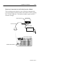
1
Allen-Bradley
Hand-Held
Cordless Bar
Code Scanners
(Cat. Nos.
2755-HCG-4 and
2755-HCG-7)
Programming
Guide
Important User Information
The illustrations, charts, sample programs and layout examples
shown in this guide are intended solely for purposes of example.
Since there are many variables and requirements associated with any
particular installation, Allen-Bradley does not assume responsibility
or liability (to include intellectual property liability) for actual use
based upon the examples shown in this publication.
Allen-Bradley publication SGI-1.1, Safety Guidelines for the
Application, Installation, and Maintenance of Solid-State Control
(available from your local Allen-Bradley office), describes some
important differences between solid-state equipment and
electromechanical devices that should be taken into consideration
when applying products such as those described in this publication.
Reproduction of the contents of this copyrighted publication, in
whole or in part, without written permission of Allen-Bradley
Company, Inc., is prohibited.
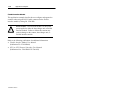
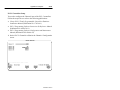
Throughout this manual we use notes to make you aware of safety
considerations:
!
ATTENTION: Identifies information about practices
or circumstances that can lead to personal injury or
death, property damage or economic loss.
Attention statements help you to:
• identify a hazard
• avoid the hazard
• recognize the consequences
SLC 5/03, SLC 5/04, AdaptaScan, MicroLogix, and DTAM are trademarks of Allen-Bradley Company, Inc.
PLC-5 is a registered trademark of Allen-Bradley Company, Inc.
DeviceNet is a trademark of the open DeviceNet Vendor Association
Table of Contents
Preface
Intended Audience . . . . . . . . . . . . . . . . . . . . . . . . . . . . . . . . . .
Contents of this Manual . . . . . . . . . . . . . . . . . . . . . . . . . . . . . . .
Related Publications . . . . . . . . . . . . . . . . . . . . . . . . . . . . . . . . .
Configuration Bar Codes . . . . . . . . . . . . . . . . . . . . . . . . . . . . . .
Chapter 1
P–1
P–1
P–2
P–2
Basic Bar Codes
Set Defaults . . . . . . . . . . . . . . . . . . . . . . . . . . . . . . . . . . . . .
Host Interface Code . . . . . . . . . . . . . . . . . . . . . . . . . . . . . . . .
Code Types . . . . . . . . . . . . . . . . . . . . . . . . . . . . . . . . . . . . .
Code Lengths . . . . . . . . . . . . . . . . . . . . . . . . . . . . . . . . . . . .
Decode Options . . . . . . . . . . . . . . . . . . . . . . . . . . . . . . . . . .
UPC-A Preamble . . . . . . . . . . . . . . . . . . . . . . . . . . . . . . . . . .
UPC-E Preamble . . . . . . . . . . . . . . . . . . . . . . . . . . . . . . . . . .
Pause Duration . . . . . . . . . . . . . . . . . . . . . . . . . . . . . . . . . . .
Prefix and Suffix . . . . . . . . . . . . . . . . . . . . . . . . . . . . . . . . . .
Data Transmission Formats . . . . . . . . . . . . . . . . . . . . . . . . . .
Laser Control . . . . . . . . . . . . . . . . . . . . . . . . . . . . . . . . . . . .
Baud Rate . . . . . . . . . . . . . . . . . . . . . . . . . . . . . . . . . . . . . .
Parity . . . . . . . . . . . . . . . . . . . . . . . . . . . . . . . . . . . . . . . . . .
Check Parity . . . . . . . . . . . . . . . . . . . . . . . . . . . . . . . . . . . . .
Hardware Handshaking . . . . . . . . . . . . . . . . . . . . . . . . . . . . .
Software Handshaking . . . . . . . . . . . . . . . . . . . . . . . . . . . . . .
Serial Response Time-Out . . . . . . . . . . . . . . . . . . . . . . . . . . .
Stop Bit Select . . . . . . . . . . . . . . . . . . . . . . . . . . . . . . . . . . .
ASCII Format . . . . . . . . . . . . . . . . . . . . . . . . . . . . . . . . . . . .
RTS Line State . . . . . . . . . . . . . . . . . . . . . . . . . . . . . . . . . . .
Intercharacter Delay . . . . . . . . . . . . . . . . . . . . . . . . . . . . . . .
1–4
1–7
1–7
1–10
1–15
1–20
1–20
1–21
1–23
1–25
1–27
1–29
1–30
1–31
1–31
1–32
1–33
1–34
1–35
1–35
1–36
Publication 2755-6.6
Publication 2755-6.6
toc–ii
Table of Contents
Transmit Code ID Character . . . . . . . . . . . . . . . . . . . . . . . . . .
Transmit AIM Code ID . . . . . . . . . . . . . . . . . . . . . . . . . . . . . .
Ignore Unknown Characters . . . . . . . . . . . . . . . . . . . . . . . . . .
International Keyboard Emulation . . . . . . . . . . . . . . . . . . . . . .
International Keyboard Emulation Fast Transmit . . . . . . . . . . .
National keyboard Types . . . . . . . . . . . . . . . . . . . . . . . . . . . .
Set Transmission Frequency . . . . . . . . . . . . . . . . . . . . . . . . .
Wait for Host Interface Response Time . . . . . . . . . . . . . . . . . .
Chapter 2
1–37
1–38
1–38
1–39
1–39
1–40
1–41
1–43
Advanced Data Format Bar Codes
ADF Overview . . . . . . . . . . . . . . . . . . . . . . . . . . . . . . . . . . . . .
Criteria . . . . . . . . . . . . . . . . . . . . . . . . . . . . . . . . . . . . . . . . .
Actions . . . . . . . . . . . . . . . . . . . . . . . . . . . . . . . . . . . . . . . . .
Rules Hierarchy . . . . . . . . . . . . . . . . . . . . . . . . . . . . . . . . . . . .
Criteria . . . . . . . . . . . . . . . . . . . . . . . . . . . . . . . . . . . . . . . . .
Special Commands . . . . . . . . . . . . . . . . . . . . . . . . . . . . . . . .
Actions . . . . . . . . . . . . . . . . . . . . . . . . . . . . . . . . . . . . . . . . .
Numeric Keypad . . . . . . . . . . . . . . . . . . . . . . . . . . . . . . . . . .
Alphanumeric Keypad . . . . . . . . . . . . . . . . . . . . . . . . . . . . . .
2–1
2–2
2–3
2–3
2–4
2–10
2–11
2–52
2–54
Appendix A Application Examples
Enhanced Decoder . . . . . . . . . . . . . . . . . . . . . . . . . . . . . . . . . . A–2
Hardware Connections for AUX Port Pass-Through . . . . . . . . . A–3
Configuration Codes for the AUX Port Pass-Through . . . . . . . . A–4
Enhanced Decoder Setup for the AUX Port Pass-Through . . . . A–5
Flexible Interface Module . . . . . . . . . . . . . . . . . . . . . . . . . . . . . . A–6
Hardware Connections for the Flexible Interface Module . . . . . . A–7
Configuration Codes for the Flexible Interface Module . . . . . . . A–8
Flexible Interface Module Setup . . . . . . . . . . . . . . . . . . . . . . . A–9
SLC 5/03 and SLC 5/04 Controllers . . . . . . . . . . . . . . . . . . . . . . A–12
Hardware Connections for the SLC 5/03 and
SLC 5/04 Controllers . . . . . . . . . . . . . . . . . . . . . . . . . . . . . . . A–13
Publication 2755-6.6
Table of Contents
toc–iii
Configuration Codes for the SLC 5/03 and SLC 5/04 Controllers
SLC 5/03 and SLC 5/04 Controllers Setup . . . . . . . . . . . . . . . .
SLC Program . . . . . . . . . . . . . . . . . . . . . . . . . . . . . . . . . . . .
PLC-5 Controllers . . . . . . . . . . . . . . . . . . . . . . . . . . . . . . . . . . .
Hardware Connections for the PLC-5 Controllers . . . . . . . . . . .
Configuration Codes for the PLC-5 Controllers . . . . . . . . . . . . .
PLC-5 Controllers Setup . . . . . . . . . . . . . . . . . . . . . . . . . . . .
PLC Program . . . . . . . . . . . . . . . . . . . . . . . . . . . . . . . . . . . . . .
AdaptaScan Pass-Through . . . . . . . . . . . . . . . . . . . . . . . . . . . .
Hardware Connections for the AdaptaScan Bar Code Reader . .
Configuration Codes for the AdaptaScan Bar Code Readers . . .
AdaptaScan Bar Code Readers Setup . . . . . . . . . . . . . . . . . .
DTAM Plus DeviceNet . . . . . . . . . . . . . . . . . . . . . . . . . . . . . . . .
Hardware Connections for the DTAM Plus Operator Interface . .
Configuration Codes for the DTAM Plus Operator Interface . . . .
DTAM Plus Operator Interface Setup . . . . . . . . . . . . . . . . . . .
DeviceNet Operation . . . . . . . . . . . . . . . . . . . . . . . . . . . . . . .
A–14
A–17
A–19
A–20
A–21
A–22
A–25
A–27
A–28
A–29
A–31
A–33
A–34
A–35
A–36
A–38
A–39
Appendix B ASCII Table
ASCII Key Values . . . . . . . . . . . . . . . . . . . . . . . . . . . . . . . . . . .
ALT Key Values . . . . . . . . . . . . . . . . . . . . . . . . . . . . . . . . . . . . .
Miscellaneous Key Values . . . . . . . . . . . . . . . . . . . . . . . . . . . . .
PF Key Values . . . . . . . . . . . . . . . . . . . . . . . . . . . . . . . . . . . . .
F Key Values . . . . . . . . . . . . . . . . . . . . . . . . . . . . . . . . . . . . . .
Numeric Key Values . . . . . . . . . . . . . . . . . . . . . . . . . . . . . . . . .
Extended Keypad Key Values . . . . . . . . . . . . . . . . . . . . . . . . . . .
B–2
B–5
B–5
B–6
B–6
B–7
B–7
Publication 2755-6.6
Publication 2755-6.6
Preface
Read this preface to familiarize yourself with the rest of the manual.
This preface covers the following topics:
• intended audience
• contents of this manual
• related publications
• configuration bar codes
Intended Audience
No special knowledge is required to understand this document or use
of the scanner. Cordless scanners may be used with a variety of host
devices. You should be familiar with the host’s communication
ports.
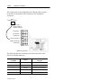
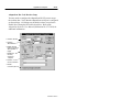
Contents of this Manual
The following table briefly describes the contents of each section.
Chapter
Title
Contents
Describes the purpose, background, and
scope of this manual. Also provides a list
of related publications.
Preface
1
Basic Bar Codes
Provides the basic bar codes that can be
used with the scanners.
2
Advanced Data Format
Bar Codes
Provides the advanced bar codes that can
be used with the scanners.
Appendix A
Application Examples
Provides examples on using the standard
and long range hand-held cordless bar
code scanners.
Appendix B
ASCII Table
Lists ASCII conversion chart including
Code 39 Full ASCII encoded characters.
Publication 2755-6.6
Publication 2755-6.6
P–2
Preface
Related Publications
Below is a list of related publications you may need to refer to when
using the cordless scanners.
Publication No.
Title
2755-6.3
Hand-Held Cordless Bar Code Scanners User Manual
2755-921
Bar Code Basics
Configuration Bar Codes
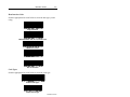
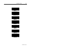
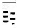
The configuration bar code symbols are Code 128. The scanner is
always enabled to read Code 128 bar codes. Default settings are
indicated by an asterisk*. Refer to the example below.
9600*
Publication 2755-6.6
Publication 2755-6.6
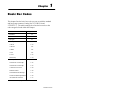
Chapter
1
Basic Bar Codes
This chapter lists the basic bar codes you can use with the standard
and long range scanners (Catalog Nos. 2755-HCG-4 and
2755-HCG-7). The table starting below lists the bar codes or bar
code categories found within this chapter.
Parameter
Page Location
Set Defaults
1–4
Host Interface
1–7
Code Types
1–7
Code Lengths
Code 39
1–10
Code 128
1–11
Codabar
1–11
I 2 of 5
1–11
D 2 of 5
1–12
MSI Plessey
1–13
Decode Options
Transmit UPC-A Check Digit
1–15
Transmit UPC-E Check Digit
1–15
Convert UPC-E to UPC-A
1–16
EAN Zero Extend
1–16
Transmit No Decode Message
1–17
Decode UPC/EAN Supplemental
1–16
ITF-14/EAN-13 Conversion
1–17
Table continued on the next page.
Publication 2755-6.6
1–2
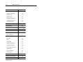
Basic Bar Codes
Parameter
Page Location
Transmit Code 39 Check Digit
1–17
MSI Plessey Check Digit
1–15
Buffer Code 39
1–17
Beeper Volume
1–18
Beep After Good Decode
1–18
UPC/EAN Security Level
1–19
Decode Redundancy
1–19
UPC-A Preamble
1–20
UPC-E Preamble
1–20
Pause Duration
1–21
Prefix/Suffix Values
1–23
Scan Data Transmission Format
1–25
Laser Control
Laser On Time-Out
1–27
RS-232C Options
Baud Rate
1–29
Parity
1–30
Check Parity
1–31
Hardware Handshaking
1–31
Software Handshaking
1–32
Serial Response Time-Out
1–33
Stop Bit Select
1–34
ASCII Data Format
1–35
RTS Line State
1–35
Intercharacter Delay
1–36
Transmit Code ID Character
1–37
Transmit AIM Code ID
1–38
Table continued on the next page.
Publication 2755-6.6
Basic Bar Codes
Parameter
1–3
Page Location
Ignore Unknown Characters
1–38
International Keypad Emulation
1–39
International Keypad Emulation
Fast Xmit
1–39
National Keyboard Types
1–40
Set Transmission Frequency
(Channel)
1–41
Wait for Host Interface Response
Time
1–43
Publication 2755-6.6
1–4
Basic Bar Codes
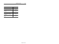
Set Defaults
The following table lists the default settings for the standard and
extended range scanners.
Description
Default Setting
Host Interface
None
Code Types
All Enabled
Code Lengths
Code 39
1 to 55
Code 128
3 to 55
Codabar
2 to 55
I 2 of 5
14
D 2 of 5
14
MSI Plessey
1 to 55
Decode Options
Transmit UPC-A Check Digit
Enabled
Transmit UPC-E Check Digit
Enabled
Convert UPC-E to UPC-A
Disabled
EAN Zero Extend
Disabled
Transmit No Decode Message
Disabled
Decode UPC/EAN Supplemental
Disabled
ITF-14/EAN-13 Conversion
Enabled
Transmit Code 39 Check Digit
Disabled
MSI Plessey Check Digit
1
Buffer Code 39
Disabled
Beeper Volume
High
Table continued on the next page.
Publication 2755-6.6
Basic Bar Codes
Description
1–5
Default Setting
Beep After Good Decode
Enabled
UPC/EAN Security Level
0
Decode Redundancy
0
UPC-A Preamble
System Character
UPC-E Preamble
System Character
Pause Duration
0
Prefix Value
None
Suffix Value
7013 ( <Enter> for wedges,
<CR/LF> for serial devices)
Scan Data Transmission Format
Data As Is
Laser Control
Laser On Time-Out
3 Seconds
RS-232C Options
Baud Rate
9600
Parity
Odd
Check Parity
Enabled
Hardware Handshaking
None
Software Handshaking
None
Serial Response Time-out
2 Seconds
Stop Bit Select
2
ASCII Data Format
7-bit
RTS Line State
Low
Intercharacter Delay
0
Transmit Code ID Character
Disabled
Transmit AIM Code ID
Disabled
Ignore Unknown Characters
Enabled
International Keypad Emulation
Disabled
Table continued on the next page.
Publication 2755-6.6
1–6
Basic Bar Codes
Description
Default Setting
International Keypad Emulation
Fast Xmit
Disabled
National Keyboard Type
U.S. English
Set Transmission Frequency
(Channel)
50
Wait for Host Interface Response
Time
00
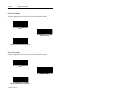
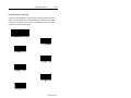
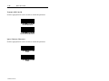
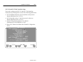
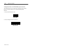
Scan this bar code to set the default settings.
Set Defaults
Publication 2755-6.6
Basic Bar Codes
1–7
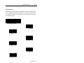
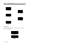
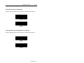
Host Interface Code
Scan the appropriate bar code below to select the host type you are
using.
Single Port RS-232
IBM PC/AT PS2-50, -55sx, -60, -70, -80 and Clones
IBM PC/XT and Clones
IBM PS2-30 and Clones
DEC VT 2xx/3xx/4xx
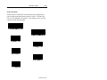
Code Types
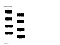
Scan the appropriate bar code below to select the code type.
Enable All Code Types
Disable All Code Types
Publication 2755-6.6
1–8
Basic Bar Codes
Add Code 39
Delete Code 39
Add Code 39 Full ASCII
Delete Code 39 Full ASCII
Add UPC/EAN
Delete UPC/EAN
Add Code 128
Delete Code 128
Publication 2755-6.6
Basic Bar Codes
1–9
Add EAN 128
Delete EAN 128
Add D 2 of 5
Delete D 2 of 5
Add I 2 of 5
Delete I 2 of 5
Add Codabar
Publication 2755-6.6
1–10
Basic Bar Codes
Delete Codabar
Add MSI Plessey
Delete MSI Plessey
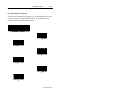
Code Lengths
Scan the appropriate bar codes to select the length type and number.
Each length must have two digits. For example, the number three is
comprised of the zero and 3 bar codes. The number 12 is comprised
of the 1 and 2 bar codes.
Code 39 – Any Length
Code 39 – Length Within Range
Code 39 – 1 Discrete Length
Publication 2755-6.6
Basic Bar Codes
1–11
Code 39 – 2 Discrete Lengths
Code 128 – Any Length
Codabar – Any Length
Codabar – Length Within Range
Codabar – 1 Discrete Length
Codabar – 2 Discrete Lengths
I 2 of 5 – Any Length
Publication 2755-6.6
1–12
Basic Bar Codes
I 2 of 5 – Length Within Range
I 2 of 5 – 1 Discrete Length
I 2 of 5 – 2 Discrete Lengths
D 2 of 5 – Any Length
D 2 of 5 – Length Within Range
D 2 of 5 – 1 Discrete Length
D 2 of 5 – 2 Discrete Lengths
Publication 2755-6.6
Basic Bar Codes
1–13
MSI Plessey – Any Length
MSI Plessey – Length Within Range
MSI Plessey – 1 Discrete Length
MSI Plessey – 2 Discrete Lengths
0
1
2
Publication 2755-6.6
1–14
Basic Bar Codes
3
4
5
6
7
8
9
Cancel
Publication 2755-6.6
Basic Bar Codes
1–15
Decode Options
Scan the appropriate bar code to enable or disable the decode option.
Transmit UPC-A Check Digit*
Do Not Transmit UPC-A Check Digit
Transmit UPC-E Check Digit*
Do Not Transmit UPC-E Check Digit
Enable 1 MSI Plessey Check Digit*
Enable 2 MSI Plessey Check Digits
Publication 2755-6.6
1–16
Basic Bar Codes
Convert UPC-E to UPC-A
Do Not Convert UPC-E to UPC-A*
Decode UPC/EAN Supplementals
Ignore UPC/EAN Supplementals
Autodiscriminate UPC/EAN Supplementals
Enable EAN Zero Extend
Disable EAN Zero Extend*
Publication 2755-6.6
Basic Bar Codes
1–17
Transmit No Decode Message
Do Not Transmit No Decode Message*
ITF14/EAN-13 Conversion Enabled*
ITF14/EAN-13 Conversion Disabled
Buffer Code 39
Do Not Buffer Code 39*
Verify Code 39 Check Digit
Publication 2755-6.6
1–18
Basic Bar Codes
Do Not Verify Code 39 Check Digit*
Bi-directional Redundancy Enabled*
Bi-directional Redundancy Disabled
Beep After Good Decode*
Do Not Beep After Good Decode
Low Beeper Volume
High Beeper Volume*
Publication 2755-6.6
Basic Bar Codes
1–19
UPC/EAN Security Level 0*
UPC/EAN Security Level 1
UPC/EAN Security Level 2
UPC/EAN Security Level 3
Decode Redundancy 1
Decode Redundancy 2
Decode Redundancy 3
Publication 2755-6.6
1–20
Basic Bar Codes
UPC-A Preamble
Scan the appropriate bar code to select one preamble option.
None
System Character*
System Character and Country Code
UPC-E Preamble
Scan the appropriate bar code to select one preamble option.
None
System Character*
System Character and Country Code
Publication 2755-6.6
Basic Bar Codes
1–21
Pause Duration
Scan the Pause Duration bar code and then scan two numbered bar
codes which represent the desired pause. The pause is measured in
0.1 second increments. If you make an error, scan the Cancel bar
code and start again.
Pause Duration
0*
1
2
3
4
5
Publication 2755-6.6
1–22
Basic Bar Codes
6
7
8
9
Cancel
Publication 2755-6.6
Basic Bar Codes
1–23
Prefix and Suffix
Scan the Prefix or Suffix bar code and then scan 4 numbered bar
codes which represent the desired prefix or suffix. The Enter key
(7013) is the default for all options. If you make an error, scan the
Cancel bar code and start again.
Scan Suffix (Value 1)
Scan Prefix (Value 2)
0
1
2
3
4
Publication 2755-6.6
1–24
Basic Bar Codes
5
6
7
8
9
Cancel
Publication 2755-6.6
Basic Bar Codes
1–25
Data Transmission Formats
Scan the:
1. Scan Options bar code.
2. bar code corresponding to the desired converted data format.
3. Enter bar code.
If you make an error, scan the Cancel bar code and start again.
Scan Options
Data As Is*
<Prefix><Data>
<Data><Suffix>
<Prefix><Data><Suffix>
Enter
Publication 2755-6.6
1–26
Basic Bar Codes
Erase All Formats
Erase Last Entered Format
Cancel
Enter
Publication 2755-6.6
Basic Bar Codes
1–27
Laser Control
Scan the Laser On Time-Out bar code and then the two bar codes
corresponding to the desired time. The pause is measured in
0.5 second increments from 0.5 seconds to 6.0 seconds. If you make
an error, scan the Cancel bar code and start again.
Laser On Time-Out
0
1
2
3
4
5
Publication 2755-6.6
1–28
Basic Bar Codes
6
7
8
9
Cancel
Publication 2755-6.6
Basic Bar Codes
1–29
Baud Rate
Scan one of the following bar codes to select the appropriate baud
rate for RS-232 transmission.
110
300
600
1200
2400
4800
9600*
19200
Publication 2755-6.6
1–30
Basic Bar Codes
Parity
Scan the appropriate bar code to set the parity of RS-232
transmissions.
Odd*
Even
Mark
Space
None
Publication 2755-6.6
Basic Bar Codes
1–31
Check Parity
Scan the appropriate bar code to check parity of RS-232
transmissions.
Check Parity*
Do Not Check Parity
Hardware Handshaking
Scan the appropriate bar code to select an RS-232 hardware
handshaking protocol.
None*
RTS/CTS
Publication 2755-6.6
1–32
Basic Bar Codes
Software Handshaking
Scan the appropriate bar code to select an RS-232 software
handshaking protocol.
None*
ACK/NAK
ACK/NAK with ENQ
ENQ Only
Publication 2755-6.6
Basic Bar Codes
1–33
Serial Response Time-Out
Scan the Serial Response Time-Out bar code and then the two bar
codes corresponding to the desired time-out. The delay can range
from zero seconds to 9.9 seconds. If you make an error, scan the
Cancel bar code and start again.
Serial Response Time-Out
0
1
2
3
4
5
Publication 2755-6.6
1–34
Basic Bar Codes
6
7
8
9
Cancel
Stop Bit Select
Scan the appropriate bar code to select the number of stop bits for
RS-232 communication.
1 Stop Bit
2 Stop Bits*
Publication 2755-6.6
Basic Bar Codes
1–35
ASCII Format
Scan the appropriate bar code to select either a 7-bit or 8-bit ASCII
format for RS-232 communication.
7-bit*
8-bit
RTS Line State
Scan the appropriate bar code to select the desired option.
Line High
Line Low*
Publication 2755-6.6
1–36
Basic Bar Codes
Intercharacter Delay
Scan the Intercharacter Delay bar code and then the two bar codes
corresponding to the desired delay. The delay can range from zero
seconds to 0.0099 seconds. If you make an error, scan the Cancel
bar code and start again.
Intercharacter Delay
0
1
2
3
4
5
Publication 2755-6.6
Basic Bar Codes
1–37
6
7
8
9
Cancel
Transmit Code ID Character
Scan the appropriate bar code to enable or disable this parameter.
Transmit Code ID Character
Do Not Transmit Code ID Character *
Publication 2755-6.6
1–38
Basic Bar Codes
Transmit AIM Code ID
Scan the appropriate bar code to enable or disable this parameter.
Transmit AIM Code ID
Do Not Transmit AIM Code ID*
Ignore Unknown Characters
Scan the appropriate bar code to enable or disable this parameter.
Enable*
Disable
Publication 2755-6.6
Basic Bar Codes
1–39
International Keyboard Emulation
Scan the appropriate bar code to enable or disable this parameter.
Enable
Disable*
International Keyboard Emulation Fast Transmit
Scan the appropriate bar code to enable or disable this parameter.
Enable
Disable*
Publication 2755-6.6
1–40
Basic Bar Codes
National keyboard Types
Scan the appropriate bar code to select a keyboard type.
US English*
French
German
French International
Spanish
Italian
Swedish
UK English
Publication 2755-6.6
Basic Bar Codes
1–41
Set Transmission Frequency
Scan the Set Transmission Frequency bar code and then the two bar
codes to set the two digit channel number. If you make an error,
scan the Cancel bar code and start again.
Select Channel Number
0
1
2
3
4
5
Publication 2755-6.6
1–42
Basic Bar Codes
6
7
8
9
Cancel
Publication 2755-6.6
Basic Bar Codes
1–43
Wait for Host Interface Response Time
Scan the Wait for Host Interface Response Time bar code and then
the two bar codes to set the two digit response time. The delay can
range from zero seconds to 99 seconds. If you make an error, scan
the Cancel bar code and start again. Programming a zero enables the
automatic Wait for a Host Response Timeout calculation feature.
Wait for Host Interface Response Time
0
1
2
3
4
5
Publication 2755-6.6
1–44
Basic Bar Codes
6
7
8
9
Cancel
Publication 2755-6.6
Chapter
2
Advanced Data Format Bar
Codes
This chapter explains what Advanced Data Format (ADF) is and lists
the bar codes you can use with the standard range and long range
scanners (Catalog Nos. 2755-HCG-4 and 2755-HCG-7). The
following table lists the bar code categories within this chapter.
Parameter
Page Location
Criteria
2–4
Special Commands
2–10
Actions
2–11
Numeric Keypad
2–52
Alphanumeric Keypad
2–54
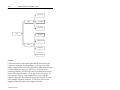
ADF Overview
ADF allows you to customize input before it is transmitted to your
host device. For example, instead of having a direct read of a bar
code, you can now attach a message to it. ADF is implemented with
a series of bar codes that have selectable parameters. (You do not
have to type in the individual characters for your message but rather
scan in the appropriate bar code located in this chapter.) This series
of bar codes is called a Rule and is used to evaluate input from the
scanner. Rules are comprised of Criteria and Actions. Criteria are
composed of an Input Source, Code Type, and Code Length.
Actions are composed of Send Data, Send Keystroke, Setup Pause,
and Send Preset Value. Criteria, Actions, and entire Rules may be
erased by scanning the appropriate bar code.
Publication 2755-6.6
2–2
Advanced Data Format Bar Codes
Input Source
Criteria
Code Type
Code Length
Rules
Send Data
Send Keystroke
Actions
Setup Pause
Send Preset Value
Criteria
Criteria are used to select the bar codes that the Actions act upon.
Criteria are composed of an Input Source, Code Type, and Code
Length. Input Source is the source affected by using using ADF and
is selected prior to creating any ADF rules. Code Type is the
symbology selected. All code types must be scanned in succession
prior to selecting other criteria. If you don’t select a code type, all
code types are affected. Code Length allows you to define the
number of characters the selected code type must contain. You can
select multiple lengths for each rule. If you do not select a code
length, selected code types of any length are affected.
Publication 2755-6.6
Advanced Data Format Bar Codes
2–3
Actions
Actions allow you to select how to format data for transmission.
Actions are composed of Send Data, Send Keystroke, Setup Pause,
and Send Preset Value. Send Data allows you to send all the data
that follows, send all the data up to a specific character selected from
the alphanumeric keyboard bar code, or send the next number of
characters (1 to 254) selected from the alphanumeric keyboard.
Send Keystroke allows you to scan the bar code for the keystroke
you wish to send. Setup Pause allows you to set the pause duration
parameter prior to entering ADF. Send Preset Value allows you to
send values 1 or 2 by scanning the appropriate bar code.
• value 1 = scan suffix
• value 2 = scan prefix
Rules Hierarchy
The last rule entered is the first rule read by the scanner. The
scanner reads the information and determines what needs to be
accomplished. If the last rule read is valid, the scanner may not go
on to the other rules so positioning of the rules is very important.
Publication 2755-6.6
2–4
Advanced Data Format Bar Codes
Criteria
Scan:
1. the code types together before selecting other Criteria.
2. the input source.
3. one length per Rule.
Code 39
Code 128
I 2of 5
Codabar
D 2 of 5
UPC-A
Publication 2755-6.6
Advanced Data Format Bar Codes
2–5
UPC-E
EAN-8
EAN-13
UPC/EAN
Any Source
Scanner Port
1
2
Publication 2755-6.6
2–6
Advanced Data Format Bar Codes
3
4
5
6
7
8
9
10
Publication 2755-6.6
Advanced Data Format Bar Codes
2–7
11
12
13
14
15
16
17
18
Publication 2755-6.6
2–8
Advanced Data Format Bar Codes
19
20
21
22
23
24
25
26
Publication 2755-6.6
Advanced Data Format Bar Codes
2–9
27
28
29
30
Publication 2755-6.6
2–10
Advanced Data Format Bar Codes
Special Commands
Scan the appropriate bar code below after scanning a criteria.
Erase Criteria and Start Again
Erase Actions and Start Again
Quit Entering Rules
Save Rule
Erase Previously Saved Rule
Erase All Rules
Publication 2755-6.6
Advanced Data Format Bar Codes
2–11
Actions
Scan the appropriate bar code to enable the desired action.
Send Pause
Send Value 1
Send Value 2
Send Value 3
Send Value 4
Send All Data That Remains
Send Next Character
Publication 2755-6.6
2–12
Advanced Data Format Bar Codes
Send Next 2 Characters
Send Next 3 Characters
Send Next 4 Characters
Send Next 5 Characters
Send Next 6 Characters
Send Next 7 Characters
Send Next 8 Characters
Send Next 9 Characters
Publication 2755-6.6
Advanced Data Format Bar Codes
2–13
Send Next 10 Characters
Send Next 11 Characters
Send Next 12 Characters
Send Next 13 Characters
Send Next 14 Characters
Send Next 15 Characters
Send Next 16 Characters
Send Next 17 Characters
Publication 2755-6.6
2–14
Advanced Data Format Bar Codes
Send Next 18 Characters
Send Next 19 Characters
Send Next 20 Characters
Send Account Number
Send Exp Date (MMYY)
Send Exp date (YYMM)
Send Customer Name
Select Track 1 Data
Publication 2755-6.6
Advanced Data Format Bar Codes
2–15
Select Track 2 Data
Select Track 3 Data
Send Discretionary Data
Skip Ahead 1 Character
Skip Ahead 2 Characters
Skip Ahead 3 Characters
Skip Ahead 4 Characters
Skip Ahead 5 Characters
Publication 2755-6.6
2–16
Advanced Data Format Bar Codes
Skip Ahead 6 Characters
Skip Ahead 7 Characters
Skip Ahead 8 Characters
Skip Ahead 9 Characters
Skip Ahead 10 Characters
Send Control 2
Send Control A
Send Control B
Publication 2755-6.6
Advanced Data Format Bar Codes
2–17
Send Control C
Send Control D
Send Control E
Send Control F
Send Control G
Send Control H
Send Control I
Send Control J
Publication 2755-6.6
2–18
Advanced Data Format Bar Codes
Send Control K
Send Control L
Send Control M
Send Control N
Send Control O
Send Control P
Send Control Q
Send Control R
Publication 2755-6.6
Advanced Data Format Bar Codes
2–19
Send Control S
Send Control T
Send Control U
Send Control V
Send Control W
Send Control X
Send Control Y
Send Control Z
Publication 2755-6.6
2–20
Advanced Data Format Bar Codes
Send Control [
Send Control \
Send Control ]
Send Control 6
Send Control –
Send Space
Send !
Send “
Publication 2755-6.6
Advanced Data Format Bar Codes
2–21
Send #
Send $
Send %
Send &
Send ‘
Send (
Send )
Send *
Publication 2755-6.6
2–22
Advanced Data Format Bar Codes
Send +
Send ,
Send –
Send .
Send /
Send 0
Send 1
Send 2
Publication 2755-6.6
Advanced Data Format Bar Codes
2–23
Send 3
Send 4
Send 5
Send 6
Send 7
Send 8
Send 9
Send :
Publication 2755-6.6
2–24
Advanced Data Format Bar Codes
Send ;
Send <
Send =
Send >
Send ?
Send @
Send A
Send B
Publication 2755-6.6
Advanced Data Format Bar Codes
2–25
Send C
Send D
Send E
Send F
Send G
Send H
Send I
Send J
Publication 2755-6.6
2–26
Advanced Data Format Bar Codes
Send K
Send L
Send M
Send N
Send O
Send P
Send Q
Send R
Publication 2755-6.6
Advanced Data Format Bar Codes
2–27
Send S
Send T
Send U
Send V
Send W
Send X
Send Y
Send Z
Publication 2755-6.6
2–28
Advanced Data Format Bar Codes
Send [
Send \
Send ]
Send ^
Send _
Send ‘
Send a
Send b
Publication 2755-6.6
Advanced Data Format Bar Codes
2–29
Send c
Send d
Send e
Send f
Send g
Send h
Send i
Send j
Publication 2755-6.6
2–30
Advanced Data Format Bar Codes
Send k
Send l
Send m
Send n
Send o
Send p
Send q
Send r
Publication 2755-6.6
Advanced Data Format Bar Codes
2–31
Send s
Send t
Send u
Send v
Send w
Send x
Send y
Send z
Publication 2755-6.6
2–32
Advanced Data Format Bar Codes
Send {
Send |
Send }
Send ~
Send Alt 2
Send Alt A
Send Alt B
Send Alt C
Publication 2755-6.6
Advanced Data Format Bar Codes
2–33
Send Alt D
Send Alt E
Send Alt F
Send Alt G
Send Alt H
Send Alt I
Send Alt J
Send Alt K
Publication 2755-6.6
2–34
Advanced Data Format Bar Codes
Send Alt L
Send Alt M
Send Alt N
Send Alt O
Send Alt P
Send Alt Q
Send Alt R
Send Alt S
Publication 2755-6.6
Advanced Data Format Bar Codes
2–35
Send Alt T
Send Alt U
Send Alt V
Send Alt W
Send Alt X
Send Alt Y
Send Alt Z
Send Alt [
Publication 2755-6.6
2–36
Advanced Data Format Bar Codes
Send Alt \
Send Alt ]
Send Alt 6
Send Alt –
Send PA 1
Send PA 2
Send CMD 1
Send CMD 2
Publication 2755-6.6
Advanced Data Format Bar Codes
2–37
Send CMD 3
Send CMD 4
Send CMD 5
Send CMD 6
Send CMD 7
Send CMD 8
Send CMD 9
Send CMD 10
Publication 2755-6.6
2–38
Advanced Data Format Bar Codes
Send Yen Character
Send Pound Sterling Character
Send Bomb Character
Send Hook Character
Send Bullet Character
Send 1/2 Character
Send Paragraph Character
Send Section Character
Publication 2755-6.6
Advanced Data Format Bar Codes
2–39
Send Vertical Character
Send Keypad *
Send Keypad +
Send Keypad –
Send Keypad .
Send Keypad /
Send Keypad 0
Send Keypad 1
Publication 2755-6.6
2–40
Advanced Data Format Bar Codes
Send Keypad 2
Send Keypad 3
Send Keypad 4
Send Keypad 5
Send Keypad 6
Send Keypad 7
Send Keypad 8
Send Keypad 9
Publication 2755-6.6
Advanced Data Format Bar Codes
2–41
Send Keypad Enter
Send Keypad Num Lock
Send Break Key
Send Delete Key
Send Page Up Key
Send End Key
Send Page Down Key
Send Pause Key
Publication 2755-6.6
2–42
Advanced Data Format Bar Codes
Send Scroll Lock Key
Send Backspace Key
Send Tab Key
Send Print Screen Key
Send Insert Key
Send Home Key
Send Enter Key
Send Escape Key
Publication 2755-6.6
Advanced Data Format Bar Codes
2–43
Send Up Arrow Key
Send Down Arrow Key
Send Left Arrow Key
Send Right Arrow Key
Send Back Tab Character
Send F1 Key
Send F2 Key
Send F3 Key
Publication 2755-6.6
2–44
Advanced Data Format Bar Codes
Send F4 Key
Send F5 Key
Send F6 Key
Send F7 Key
Send F8 Key
Send F9 Key
Send F10 Key
Send F11 Key
Publication 2755-6.6
Advanced Data Format Bar Codes
2–45
Send F12 Key
Send F13 Key
Send F14 Key
Send F15 Key
Send F16 Key
Send F17 Key
Send F18 Key
Send F19 Key
Publication 2755-6.6
2–46
Advanced Data Format Bar Codes
Send F20 Key
Send F21 Key
Send F22 Key
Send F23 Key
Send F24 Key
Send F25 Key
Send F26 Key
Send F27 Key
Publication 2755-6.6
Advanced Data Format Bar Codes
2–47
Send F28 Key
Send F29 Key
Send F30 Key
Send PF1 Key
Send PF2 Key
Send PF3 Key
Send PF4 Key
Send PF5 Key
Publication 2755-6.6
2–48
Advanced Data Format Bar Codes
Send PF6 Key
Send PF7 Key
Send PF8 Key
Send PF9 Key
Send PF10 Key
Send PF11 Key
Send PF12 Key
Send PF13 Key
Publication 2755-6.6
Advanced Data Format Bar Codes
2–49
Send PF14 Key
Send PF15 Key
Send PF16 Key
Send PF17 Key
Send PF18 Key
Send PF19 Key
Send PF20 Key
Send PF21 Key
Publication 2755-6.6
2–50
Advanced Data Format Bar Codes
Send PF22 Key
Send PF23 Key
Send PF24 Key
Send PF25 Key
Send PF26 Key
Send PF27 Key
Send PF28 Key
Send PF29 Key
Publication 2755-6.6
Advanced Data Format Bar Codes
2–51
Send PF30 Key
Publication 2755-6.6
2–52
Advanced Data Format Bar Codes
Numeric Keypad
These keys are the not the same as those on an alphanumeric keypad.
0
1
2
3
4
5
Publication 2755-6.6
Advanced Data Format Bar Codes
2–53
6
7
8
9
Cancel
Publication 2755-6.6
2–54
Advanced Data Format Bar Codes
Alphanumeric Keypad
These keys are the not the same as those on a numeric keypad.
Space
#
$
%
*
+
–
Publication 2755-6.6
Advanced Data Format Bar Codes
2–55
.
/
!
“
&
‘
(
)
Publication 2755-6.6
2–56
Advanced Data Format Bar Codes
:
;
<
=
>
?
@
[
Publication 2755-6.6
Advanced Data Format Bar Codes
2–57
\
]
^
_
‘
0
1
2
Publication 2755-6.6
2–58
Advanced Data Format Bar Codes
3
4
5
6
7
8
9
A
Publication 2755-6.6
Advanced Data Format Bar Codes
2–59
B
C
D
E
F
G
H
I
Publication 2755-6.6
2–60
Advanced Data Format Bar Codes
J
K
L
M
N
O
P
Q
Publication 2755-6.6
Advanced Data Format Bar Codes
2–61
R
S
T
U
V
W
X
Y
Publication 2755-6.6
2–62
Advanced Data Format Bar Codes
Z
Cancel
End of Message
a
b
c
d
e
Publication 2755-6.6
Advanced Data Format Bar Codes
2–63
f
g
h
i
j
k
l
m
Publication 2755-6.6
2–64
Advanced Data Format Bar Codes
n
o
p
q
r
s
t
u
Publication 2755-6.6
Advanced Data Format Bar Codes
2–65
v
w
x
y
z
(
|
)
Publication 2755-6.6
2–66
Advanced Data Format Bar Codes
~
Publication 2755-6.6
Appendix
A
Application Examples
This appendix is designed to illustrate various applications for the
standard and long range cordless scanners
(Catalog Nos. 2755-HCG-4 and 2755-HCG-7). Application
examples include:
• enhanced decoder
• flexible interface module
• SLC 5/03t and SLC 5/04t controllers
• PLC-5R controller
• AdaptaScant pass-through
• DTAMt Plus DeviceNett
Because of the variety of uses for this information, the user of and
those responsible for applying this information must satisfy
themselves as to the acceptability of each application. In no event
will Allen–Bradley Company be responsible or liable for indirect or
consequential damages resulting from the use of application of this
information.
The examples shown in this appendix are intended solely to illustrate
the principles of the scanners and some of the methods used to apply
them. Particularly because of the many requirements associated with
any particular installation, Allen–Bradley Company cannot assume
responsibility or liability for actual use based upon the illustrative
uses and applications.
Publication 2755-6.6
A–2
Application Examples
Enhanced Decoder
This application example describes how to configure and operate the
scanners when using an RS-232 cable connected to the AUX port of
an Allen-Bradley Enhanced Decoder (Catalog No. 2755-DD/DS).
This application example also provides configuration information for
an Auxiliary Port Pass-Through application for the enhanced
decoder.
!
ATTENTION: Do not install the RS-232 cable with
power applied to either the base/charger unit or
enhanced decoder. Failure to follow this caution may
result in damage to the scanner, base/charger unit, or
enhanced decoder.
Refer to the Enhanced Decoder User Manual
(Publication No. 2755-833) for additional information on the
enhanced decoder.
Publication 2755-6.6
Application Examples
A–3
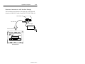
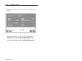
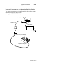
Hardware Connections for AUX Port Pass-Through
The base/charger unit connects to an input port on the enhanced
decoder with an RS-232 cable (Catalog No. 2755-HCC-BR1-06).
Base/Charger Unit
RS-232C Cable
Power Supply
To Enhanced Decoder
To Power Receptacle
Enhanced Decoder
Publication 2755-6.6
A–4
Application Examples
Configuration Codes for the AUX Port Pass-Through
After making the necessary connections, scan the bar codes starting
below to set up the scanner for use with the enhanced decoder.
1. Scan the Set Defaults bar code.
Set Defaults
2. Scan the Single Port RS-232 bar code.
Single Port RS-232
3. Scan the Parity bar code.
None
Publication 2755-6.6
Application Examples
A–5
4. Scan the Stop Bit Select bar code.
1 Stop Bit
5. Scan the ASCII Format bar code.
8-bit
Enhanced Decoder Setup for the AUX Port Pass-Through
You need to configure the enhanced decoder. Follow the steps below
or refer to the Enhanced Decoder User Manual
(Publication No. 2755-833).
1. Select Aux Terminal Data Entry (Screen 8) from the Main Menu.
2. Set Enable Keyboard Entry = Yes
3. Save and Exit the configuration.
4. Move internal selector (jumper) to the data entry position on the
system board (B-5, B-6).
5. Make sure the hand-held scanner baud rate = 9600,
parity = None, data bits = 8, and stop bits = 1.
6. See Chapter 13 of Enhanced Decoder User Manual
(Publication No. 2755-833) for additional information.
Publication 2755-6.6
A–6
Application Examples
Flexible Interface Module
This application example describes how to configure and operate the
scanners when using an RS-232 cable connected to the flexible
interface module (Catalog No. 2760-RB).
!
ATTENTION: Do not install the RS-232 cable with
power applied to either the base/charger unit or flexible
interface module. Failure to follow this caution may
result in damage to the scanner, base/charger unit, or
flexible interface module.
Refer to the following publications for additional information.
• Flexible Interface Module User Manual
(Publication No. 2760-ND001)
• SFC1 or SFC2 Protocol Cartridge User Manuals
(Publication Nos. 2760-ND002 or 2760-822)
Publication 2755-6.6
Application Examples
A–7
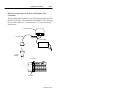
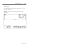
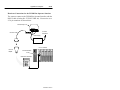
Hardware Connections for the Flexible Interface Module
The base/charger unit connects to one of the three communication
ports on the flexible interface module with an RS-232 cable (Catalog
No. 2755-HCC-BR2-06). The interface module requires an SFC2
Protocol Cartridge.
Base/Charger Unit
RS-232C Cable
Power Supply
To Power Receptacle
SFC2 Protocol Cartridge
Flexible Interface Module
Publication 2755-6.6
A–8
Application Examples
Configuration Codes for the Flexible Interface Module
After making the necessary connections, scan the bar codes starting
below to set up the scanner for use with the flexible interface
module.
1. Scan the Set Defaults bar code.
Set Defaults
2. Scan the Single Port RS-232 bar code.
Single Port RS-232
3. Scan the Parity bar code.
None
Publication 2755-6.6
Application Examples
A–9
4. Scan the ASCII Format bar code.
8-bit
The cable defaults work with the flexible interface module. Your
application may have specific requirements. If you change a
communication setting, make sure the flexible interface module is
configured to accept the change.
Flexible Interface Module Setup
You need to configure the flexible interface module. Follow the
steps below or refer to the Flexible Interface Module User Manual
(Publication No. 2760-ND001) or the SFC1 or SFC2 Protocol
Cartridge User Manuals (Publication Nos. 2760-ND002 or
2760-822).
1. Select 90B to reset the configuration to factory defaults.
2. Configure screens 3, 21, and 11 (in this order) as shown on the
following pages.
Publication 2755-6.6
A–10
Application Examples
2760–RB
SERIES A REVISION J
COPYRIGHT 1989
ALLEN–BRADLEY COMPANY, INC.
––––––––––––––––––––––––––––––––––––––––––––––––––––
1X – CONFIGURATION PARAMETERS
2X – IDENTIFICATION NUMBERS
3 – DEVICE PORT PROTOCOL NAMES
4DM – MATCH CODE ENTRIES
5I – DISCRETE BYTE INPUT ENTRIES
6 – THE DATA MATRIX ENTRIES
7 – THE PASS THROUGH ENTRIES
8 – NON–VOLATILE SCRATCH PAD AREA
9XF – RB MODULE FUNCTIONS
AX – HARDWARE DIAGNOSTICS
BX – SOFTWARE DIAGNOSTICS
C – EXIT CONFIGURATION MODE
WHERE X (0 TO 7) AND D (1 TO 3) ARE PORT NUMBERS WHICH ARE DEFINED BELOW :
0 – RB CMMND PRCSS 2 – SERIAL PORT 2 4 – CONFIG PORT 6 – I/O RACK SLT 1
1 – SERIAL PORT 1 3 – SERIAL PORT 3 5 – I/O RACK SLT 0 7 – RESERVED
WHERE F (A TO E) ARE FUNCTIONS THAT RB CAN PERFORM WHICH ARE DEFINED BELOW :
A – RESET B – SET DEFAULTS C – FLUSH D – INITIALIZE E – CLEAR DIAGS
WHERE M (A TO T) AND I (A TO H) ARE ENTRY NUMBERS FOR THE SELECTION MADE ABOVE.
ENTER A MAIN MENU SELECTION:
ENTER A MAIN MENU SELECTION: 3
PORT 1 = COPYRIGHT 1989
ALLEN–BRADLEY COMPANY, INC.
2760–SFC1 DT , SERIES A , REVISION B (YES/NO) = YES.
PORT 2 = COPYRIGHT 1989
ALLEN–BRADLEY COMPANY, INC.
2760–SFC1 DT , SERIES A , REVISION B (YES/NO) = YES.
PORT 3 = COPYRIGHT 1989
ALLEN–BRADLEY COMPANY, INC.
2760–SFC1 DT , SERIES A , REVISION B (YES/NO) = YES.
EDIT THIS SELECTION (YES/NO) ?
Publication 2755-6.6
Application Examples
A–11
ENTER A MAIN MENU SELECTION: 21
DUMB TERM. UNSPECIFIED PROTOCOL, 13fh (YES/NO) = YES.
EDIT THIS SELECTION (YES/NO) ?
ENTER A MAIN MENU SELECTION: 11
MODEM CONTROL (ENABLE/DISABLE) = DISABLE.
9600 BITS PER SECOND (YES/NO) = YES.
8 BITS NO PARITY (YES/NO) = YES.
XON/XOFF (ENABLE/DISABLE) = DISABLE.
RS232 (YES/NO) = YES.
RECEIVE MATRIXING (ENABLE/DISABLE) = DISABLE.
BYTE SWAPPING (ENABLE/DISABLE) = ENABLE.
BINARY DATA NO CONVERSIONS (YES/NO) = YES.
HDR/TLR ON OUTPUT (ENABLE/DISABLE) = ENABLE.
HEADER BYTE LENGTH (DEC 0...4) = 0.
HEADER DATA[0] (HEX 0...ff) = 0.
HEADER DATA[1] (HEX 0...ff) = 0.
HEADER DATA[2] (HEX 0...ff) = 0.
HEADER DATA[3] (HEX 0...ff) = 0.
TRAILER BYTE LENGTH (DEC 0...4) = 2.
TRAILER DATA[0] (HEX 0...ff) = a.
TRAILER DATA[1] (HEX 0...ff) = d.
TRAILER DATA[2] (HEX 0...ff) = 0.
TRAILER DATA[3] (HEX 0...ff) = 0.
MAX DATA BYTE LENGTH (DEC 0...124) = 0.
MIN DATA BYTE LENGTH (DEC 0...124) = 0.
CONTINUE THIS SELECTION (YES/NO) ?
3. Make sure PLC program is written to access Flexible Interface
Module data.
Publication 2755-6.6
A–12
Application Examples
SLC 5/03 and SLC 5/04 Controllers
This application example describes how to configure and operate the
scanners when using an RS-232 cable connected to the SLC 5/03
(Catalog No. 1747-L532) and SLC 5/04 controllers
(Catalog Nos. 1747-L541, 1747-L542, and 1747-L543).
!
ATTENTION: Do not install the RS-232 cable with
power applied to either the base/charger unit or SLC
5/03 or SLC 5/04 controllers. Failure to follow this
caution may result in damage to the scanner,
base/charger unit, or SLC 5/03 or SLC 5/04 controllers.
Refer to the following publications for additional information.
• SLC 500 Modular Hardware Style Installation and Operation
Manual (Publication No. 1747-6.2)
• SLC 500 and MicroLogixt 1000 Instruction Set Reference
Manual (Publication No. 1747-6.15)
• Advanced Programming Software User Manual
(Publication No. 9399-APSUM-11.15.95)
Publication 2755-6.6
Application Examples
A–13
Hardware Connections for the SLC 5/03 and SLC 5/04
Controllers
The base/charger unit connects to one of the communication ports on
the SLC 5/03 or SLC 5/04 controllers with an RS-232 cable (Catalog
No. 2755-HCC-BR1-06). You need to use a 25–9 pin connector as
shown below.
Base/Charger Unit
RS-232C Cable
Power Supply
To Power Receptacle
25–9 Pin
Adapter
SLC 5/04
Channel 0
Publication 2755-6.6
A–14
Application Examples
Configuration Codes for the SLC 5/03 and SLC 5/04 Controllers
After making the necessary connections, scan the bar codes starting
below to set up the scanner for use with the SLC 5/03 and SLC 5/04
controllers.
1. Scan the Set Defaults bar code.
Set Defaults
2. Scan the Single Port RS-232 bar code.
Single Port RS-232
Publication 2755-6.6
Application Examples
A–15
3. Scan the following bar codes.
Scan Suffix (Value 1)
7
0
1
3
4. Scan the Data Transmission Format bar code.
<Data><Suffix>
Publication 2755-6.6
A–16
Application Examples
5. Scan the Parity bar code.
Even
The cable defaults work with the SLC 5/03 and SLC 5/04
controllers. Your application may have specific requirements. If you
change a communication setting, make sure the SLC 5/03 and SLC
5/04 controllers are configured to accept the change.
Publication 2755-6.6
Application Examples
A–17
SLC 5/03 and SLC 5/04 Controllers Setup
You need to configure the SLC 5/03 and SLC 5/04 controllers.
Follow the steps starting below or refer to the following publications:
• SLC 500 Modular Hardware Style Installation and Operation
Manual (Publication No. 1747-6.2)
• SLC 500 and MicroLogixt 1000 Instruction Set Reference
Manual (Publication No. 1747-6.15)
• Advanced Programming Software User Manual
(Publication No. 9399-APSUM-11.15.95)
1. Set the SLC Channel 0 to User in the Channel 0 Configuration
screen
Publication 2755-6.6
A–18
Application Examples
2. Configure Channel 0 in the Channel 0 User Mode Configuration
screen.
Note that Termination 1 is set for \a or Line Feed [LF], and
Termination 2 is set for \d or Carriage Return [CR]. These
terminators, along with the ARL instruction in the SLC, allow
you to read one message at a time with [CR] [LF] terminators.
Publication 2755-6.6
Application Examples
A–19
SLC Program
The sample ladder logic listing below instructs the SLC 5/03 and
SLC 5/04 controllers to:
Rung 2:0 – Read one string of ASCII data terminated with a
[CR] [LF].
Publication 2755-6.6
A–20
Application Examples
PLC-5 Controllers
This application example describes how to configure and operate the
scanners when using an RS-232 cable connected to the PLC-5
controllers (Catalog Nos. 1785-L11B, 1785-L20B, 1785-L30B,
1785-L40B, 1785-L60B, and 1785-L80B).
!
ATTENTION: Do not install the RS-232 cable with
power applied to either the base/charger unit or PLC-5
controllers. Failure to follow this caution may result in
damage to the scanner, base/charger unit, or PLC-5
controllers.
Refer to the following publications for additional information.
• Classic PLC-5 Family Programmable Controllers Hardware
Installation Manual (Publication No. 1785-6.6.1)
• PLC-5 Programming Software Instruction Set Reference Manual
(Publication No. 6200-6.4.11)
• PLC-5 Programming Software Configuration and Maintenance
Manual (Publication No. 6200-6.4.6)
Publication 2755-6.6
Application Examples
A–21
Hardware Connections for the PLC-5 Controllers
The base/charger unit connects to the PLC-5 controllers with an
RS-232 cable (Catalog No. 2755-HCC-BR2-06).
Base/Charger Unit
RS-232C Cable
Power Supply
To Power Receptacle
PLC-5
To Channel 0 Port
Publication 2755-6.6
A–22
Application Examples
Configuration Codes for the PLC-5 Controllers
After making the necessary connections, scan bar codes starting
below to set up the scanner for use with the PLC-5 controllers.
1. Scan the Set Defaults bar code.
Set Defaults
2. Scan the Single Port RS-232 bar code.
Single Port RS-232
Publication 2755-6.6
Application Examples
A–23
3. Scan the following bar codes.
Scan Suffix (Value 1)
7
0
1
3
4. Scan the Data Transmission Format bar code.
<Data><Suffix>
Publication 2755-6.6
A–24
Application Examples
5. Scan the Parity bar code.
Even
The cable defaults work with the PLC-5 controllers. Your
application may have specific requirements. If you change a
communication setting, make sure the PLC-5 controllers are
configured to accept the change.
Publication 2755-6.6
Application Examples
A–25
PLC-5 Controllers Setup
You need to configure the Channel 0 port of the PLC-5 controllers.
Follow the steps below or refer to the following publications:
• Classic PLC-5 Family Programmable Controllers Hardware
Installation Manual (Publication No. 1785-6.6.1)
• PLC-5 Programming Software Instruction Set Reference Manual
(Publication No. 6200-6.4.11)
• PLC-5 Programming Software Configuration and Maintenance
Manual (Publication No. 6200-6.4.6)
1. Set the PLC-5 Channel 0 to User in the Channel 0 Configuration
screen.
Publication 2755-6.6
A–26
Application Examples
2. Configure Channel 0 in the User Mode Channel 0 Configuration
screen.
Note that Termination 1 is set for \0xa or Line Feed [LF], and
Termination 2 is set for \0xd or Carriage Return [CR]. These
terminators, along with the ARL instruction in the PLC-5
controllers, allow you to read one message at a time with [CR] [LF]
terminators.
Publication 2755-6.6
Application Examples
A–27
PLC Program
The sample ladder logic listing below instructs the PLC-5 controllers
to:
Rung 2:0 – Read one string of ASCII data terminated with a
[CR] [LF].
Publication 2755-6.6
A–28
Application Examples
AdaptaScan Pass-Through
This application example describes how to configure and operate the
scanners when using an RS-232 cable connected to the AdaptaScan
bar code reader (Catalog Nos. 2755-SN3, 2755-SN5, and
2755-SN8).
!
ATTENTION: Do not install the RS-232 cable with
power applied to either the base/charger unit or
AdaptaScan. Failure to follow this caution may result
in damage to the scanner, base/charger unit, or
AdaptaScan.
Refer to the following publications for additional information.
• AdaptaScan Bar Code Readers User Manual
(Publication No. 2755-837)
• AdaptaScan Software User Manual (Publication No. 2755-838)
Publication 2755-6.6
Application Examples
A–29
Hardware Connections for the AdaptaScan Bar Code Reader
The scanner connects to the AdaptaScan wiring base with a custom
cable connected to the RS-232 cable
(Catalog No. 2755-HCC-BR1-06).
Base/Charger Unit
RS-232C Cable
Power Supply
To Power Receptacle
Custom Cable (see next page)
AdaptaScan Wiring Base
Publication 2755-6.6
A–30
Application Examples
The custom cable for the AdaptaScan Pass-Through Cable connects
to the RS-232 and package detect terminals in the AdaptaScan
wiring base.
25-Pin
Female DB Connector
Custom Cable
Maximum length of
18 inches (.46 meter)
Transmit (Tx)
No Connection
Receive (Rx)
Clear to Send (CTS)
Ready to Send (RTS)
Shield (SHD)
AdaptaScan Wiring Base
The following table provides the pinout connections for the cable
(DB 25-pin female connector).
Pass-Through Cable
Pin Number
Function
AdaptaScan Terminal
Connection
2
Receive Data Input
Tx (RS-232 Terminal Block)
3
Transmit Data Output
Rx (RS-232 Terminal Block)
4
CTS Input
RTS (RS–232 Terminal Block)
5
RTS Output
CTS (RS-232 Terminal Block)
Shield
Shield Ground
SHD (RS-232 Terminal Block)
Publication 2755-6.6
Application Examples
A–31
Configuration Codes for the AdaptaScan Bar Code Readers
After making the necessary connections, scan the bar codes starting
below to set up the scanner for use with the AdaptaScan.
1. Scan the Set Defaults bar code.
Set Defaults
2. Scan the Single Port RS-232 bar code.
Single Port RS-232
3. Scan the Parity bar code.
None
Publication 2755-6.6
A–32
Application Examples
4. Scan the ASCII Format bar code.
8-bit
5. Scan the Stop Bit Select bar code.
1 Stop Bit
The cable defaults work with the AdaptaScan. Your application may
have specific requirements. If you change a communication setting,
make sure the AdaptaScan is configured to accept the change.
Publication 2755-6.6
Application Examples
A–33
AdaptaScan Bar Code Readers Setup
You may need to configure the AdaptaScan RS-232 port to accept
the scanner data. Verify that the AdaptaScan serial port is configured
as shown below. All settings use the default values except for the
Enable Pass-Through to DeviceNet check box. Refer to the
AdaptaScan Software User Manual (Publication No. 2755-838) for
additional information.
1. Default is Terminal.
2. Default is
9600 Baud.
3. Default message
length is 0 (sends all
data regardless of
length).
4. Defaults are:
No Parity,
8 Data and
1 Stop Bit.
5. Default is
RS-232 Connection.
6. Enable
Pass-Through.
Publication 2755-6.6
A–34
Application Examples
DTAM Plus DeviceNet
This application example describes how to configure and operate the
scanners when using an RS-232 cable connected to a DTAM
Operator Interface (Catalog Nos. 2707-L8P1, 2707-L8P2,
2707-L40P1, 2707–L40P2, 2707–L40P4, 2707-V40P1,
2707-V40P2, or 2707-V40P2N) on a DeviceNet network.
!
ATTENTION: Do not install the RS-232 cable with
power applied to either the base/charger unit or DTAM
Operator Interface. Failure to follow this caution may
result in damage to the scanner, base/charger unit, or
DTAM Operator Interface.
Refer to the following publications for additional information.
• DTAM Plus Operator Interface Module User Manual
(Publication No. 2707-800)
• DTAM Plus Devicenet Operator Interface Document Update
(Publication No. 2707-800.5)
• DTAM Programming Software Programming Manual
(Publication No. 2707-802)
• Getting Started with DTAM Plus User Manual
(Publication No. 2707-802)
Publication 2755-6.6
Application Examples
A–35
Hardware Connections for the DTAM Plus Operator Interface
The scanners connect to the DTAM Plus Operator Interface with the
RS-232 cable (Catalog No. 2755-HCC-BR1-06). You need to use a
25–9 pin connector as shown below.
Base/Charger Unit
To Power
Receptacle
RS-232C Cable
Power Supply
PLC-5 Controller
25–9 Pin
Adapter
1771-SDN Module
DTAM Plus DeviceNet
Publication 2755-6.6
A–36
Application Examples
Configuration Codes for the DTAM Plus Operator Interface
After making the necessary connections, scan the bar codes starting
below to set up the scanner for use with the DTAM Operator
Interface.
1. Scan the Set Defaults bar code.
Set Defaults
2. Scan the Single Port RS-232 bar code.
Single Port RS-232
Publication 2755-6.6
Application Examples
A–37
3. Scan the following bar codes.
Scan Suffix (Value 1)
7
0
1
3
4. Scan the Data Transmission Format bar code.
<Data><Suffix>
Publication 2755-6.6
A–38
Application Examples
5. Scan the Parity bar code.
Even
The cable defaults work with the DTAM Plus Operator Interface.
Your application may have specific requirements. If you change a
communication setting, make sure the DTAM Plus Operator
Interface is configured to accept the change.
DTAM Plus Operator Interface Setup
You may need to configure the DTAM Plus Operator Interface
RS-232 port to accept the scanner data. Follow the steps below or
refer to the DTAM Programming Software Programming Manual
(Publication No. 2707-802).
1. Open Screen Builder.
2. Open Create Screen.
3. Open Data Entry Screen.
4. Select Set Up Screen.
5. Select Data Entry.
6. Select ASCII Input.
7. Set up DTAM.
Publication 2755-6.6
Application Examples
A–39
DeviceNet Operation
The DTAM Plus DeviceNet operates as a Group 2 Server on the
DeviceNet network. It supports the Unconnected Message Manager
(UCMM). The DTAM Plus DeviceNet implements the predefined
master/slave connection set, operating as a slave device. It does not
initiate communications except for a Duplicate Node Address check
on power-up.
The DTAM Plus DeviceNet supports the polled I/O method of
exchanging data with a master, in the following sequence:
1. The designated master writes an output image to the DTAM Plus
DeviceNet using the Poll Command message.
2. The DTAM Plus DeviceNet responds to the poll command by
returning an input image back to the master in a Poll Response
message.
Note: The size of the input and output images (also referred to as
files) are individually configurable from 0 words to 121 words
each, to optimize DeviceNet network loading.
3. The DTAM Plus DeviceNet application program interacts with
data contained in the input and output files.
4. Data Display screens are used to view input and output data.
5. Data Entry screens are used to modify input and output data from
the scanner.
Publication 2755-6.6
Appendix
B
ASCII Table
This appendix lists the following key values:
• ASCII
• ALT
• miscellaneous
• PF
• F key
• numeric
• extended keypad
Publication 2755-6.6
B–2
ASCII Table
ASCII Key Values
ASCII Value
Full ASCII
Code 39
Encode
Char.
ASCII Value
Full ASCII
Code 39
Encode
Char.
Keystroke
Keystroke
1000
%U
CTRL 2
1022
$V
CTRL V
1001
$A
CTRL A
1023
$W
CTRL W
1002
$B
CTRL B
1024
$X
CTRL X
1003
$C
CTRL C
1025
$Y
CTRL Y
1004
$D
CTRL D
1026
$Z
CTRL Z
1005
$E
CTRL E
1027
%A
CTRL[
1006
$F
CTRL F
1028
%B
CTRL \
1007
$G
CTRL G
1029
%C
CTRL ]
1008
$H
CTRL H
1030
%D
CTRL 6
1009
$I
CTRL I
1031
%E
CTRL _
1010
$J
CTRL J
1032
SP
SP
1011
$K
CTRL K
1033
/A
!
1012
$L
CTRL L
1034
/B
“
1013
$M
CTRL M
1035
/C
#
1014
$N
CTRL N
1036
/D
$
1015
$O
CTRL O
1037
/E
%
1016
$P
CTRL P
1038
/F
&
1017
$Q
CTRL Q
1039
/G
’
1018
$R
CTRL R
1040
/H
(
1019
$S
CTRL S
1041
/I
)
1020
$T
CTRL T
1042
/J
*
1021
$U
CTRL U
1043
/K
+
Table continued on the next page.
Publication 2755-6.6
ASCII Table
ASCII Value
Full ASCII
Code 39
Encode
Char.
Keystroke
1044
/L
1045
B–3
ASCII Value
Full ASCII
Code 39
Encode
Char.
Keystroke
,
1069
E
E
-
-
1070
F
F
1046
.
.
1071
G
G
1047
/
/
1072
H
H
1048
0
0
1073
I
I
1049
1
1
1074
J
J
1050
2
2
1075
K
K
1051
3
3
1076
L
L
1052
4
4
1077
M
M
1053
5
5
1078
N
N
1054
6
6
1079
O
O
1055
7
7
1080
P
P
1056
8
8
1081
Q
Q
1057
9
9
1082
R
R
1058
/Z
:
1083
S
S
1059
%F
;
1084
T
T
1060
%G
<
1085
U
U
1061
%H
=
1086
V
V
1062
%I
>
1087
W
W
1063
%J
?
1088
X
X
1064
%V
@
1089
Y
Y
1065
A
A
1090
Z
Z
1066
B
B
1091
%K
[
1067
C
C
1092
%L
\
1068
D
D
1093
%M
]
Table continued on the next page.
Publication 2755-6.6
B–4
ASCII Table
ASCII Value
Full ASCII
Code 39
Encode
Char.
ASCII Value
Full ASCII
Code 39
Encode
Char.
Keystroke
Keystroke
1094
%N
^
1111
+O
o
1095
%O
_
1112
+P
p
1096
%W
’
1113
+Q
q
1097
+A
a
1114
+R
r
1098
+B
b
1115
+S
s
1099
+C
c
1116
+T
t
1100
+D
d
1117
+U
u
1101
+E
e
1118
+V
v
1102
+F
f
1119
+W
w
1103
+G
g
1120
+X
x
1104
+H
h
1121
+Y
y
1105
+I
i
1122
+Z
z
1106
+J
j
1123
%P
{
1107
+K
k
1124
%Q
|
1108
+L
l
1125
%R
}
1109
+M
m
1126
%S
~
1110
+N
n
1127
Publication 2755-6.6
Undefined
ASCII Table
B–5
ALT Key Values
ALT Key
Value
Keystroke
ALT Key
Value
Keystroke
ALT Key
Value
Keystroke
2064
ALT 2
2075
ALT K
2086
ALT V
2065
ALT A
2076
ALT L
2087
ALT W
2066
ALT B
2077
ALT M
2088
ALT X
2067
ALT C
2078
ALT N
2089
ALT Y
2068
ALT D
2079
ALT O
2090
ALT Z
2069
ALT E
2080
ALT P
2091
ALT [
2070
ALT F
2081
ALT Q
2092
ALT \
2071
ALT G
2082
ALT R
2093
ALT ]
2072
ALT H
2083
ALT S
2094
ALT 6
2073
ALT I
2084
ALT T
2095
ALT -
2074
ALT J
2085
ALT U
Keystroke
Miscellaneous Key Values
Misc. Key
Value
Keystroke
Misc. Key
Value
Keystroke
Misc. Key
Value
3001
PA 1
3009
CMD 7
3017
_
3002
PA 2
3010
CMD 8
3018
1/
2
3003
CMD 1
3011
CMD 9
3019
W
3004
CMD 2
3012
CMD 10
3020
w
3005
CMD 3
3013
O
3021
|
3006
CMD 4
3014
o
3022
0/00
3007
CMD 5
3015
h
3008
CMD 6
3016
–
Publication 2755-6.6
B–6
ASCII Table
PF Key Values
PF Key
Value
Keystroke
PF Key
Value
Keystroke
PF Key
Value
Keystroke
4001
PF 1
4009
PF 9
4017
PF 17
4002
PF 2
4010
PF 10
4018
PF 18
4003
PF 3
4011
PF 11
4019
PF 19
4004
PF 4
4012
PF 12
4020
PF 20
4005
PF 5
4013
PF 13
4021
PF 21
4006
PF 6
4014
PF 14
4022
PF 22
4007
PF 7
4015
PF 15
4023
PF 23
4008
PF 8
4016
PF 16
4024
PF 24
F Key Value
Keystroke
F Key
Value
Keystroke
F Key
Value
Keystroke
5001
F1
5014
F 14
5027
F 27
5002
F2
5015
F 15
5028
F 28
5003
F3
5016
F 16
5029
F 29
5004
F4
5017
F 17
5030
F 30
5005
F5
5018
F 18
5031
F 31
5006
F6
5019
F 19
5032
F 32
5007
F7
5020
F 20
5033
F 33
5008
F8
5021
F 21
5034
F 34
5009
F9
5022
F 22
5035
F 35
5010
F 10
5023
F 23
5036
F 36
5011
F 11
5024
F 24
5037
F 37
5012
F 12
5025
F 25
5038
F 38
5013
F 13
5026
F 26
5039
F 39
F Key Values
Publication 2755-6.6
ASCII Table
B–7
Numeric Key Values
Numeric
Key Value
Keystroke
Numeric
Key Value
Keystroke
Numeric
Key Value
Keystroke
6042
*
6049
1
6056
8
6043
+
6050
2
6057
9
6044
Undefined
6051
3
6058
Enter
6045
–
6052
4
6059
Num Lock
6046
.
6053
5
6060
00
6047
/
6054
6
6048
0
6055
7
Extended Keypad Key Values
Numeric
Key Value
Keystroke
Numeric
Key Value
Keystroke
Numeric
Key Value
Keystroke
7001
Break
7008
Backspace
7015
Up Arrow
7002
Delete
7009
Tab
7016
Down Arrow
7003
Page Up
7010
Print Screen
7017
Left Arrow
7004
End
7011
Insert
7018
Right Arrow
7005
Page Down
7012
Home
7019
Back Tab
7006
Pause
7013
Enter
7007
Scroll Lock
7014
Escape
Publication 2755-6.6
Index
Numbers
0, 1-13, 1-21, 1-23, 1-27, 1-33,
1-36, 1-41, 1-43, A-15,
A-23, A-37
1, 1-13, 1-21, 1-23, 1-27, 1-33,
1-36, 1-41, 1-43, A-15,
A-23, A-37
2, 1-13, 1-21, 1-23, 1-27, 1-33,
1-36, 1-41, 1-43
3, 1-14, 1-21, 1-23, 1-27, 1-33,
1-36, 1-41, 1-43, A-15,
A-23, A-37
4, 1-14, 1-21, 1-23, 1-27, 1-33,
1-36, 1-41, 1-43
5, 1-14, 1-21, 1-24, 1-27, 1-33,
1-36, 1-41, 1-43
6, 1-14, 1-22, 1-24, 1-28, 1-34,
1-37, 1-42, 1-44
7, 1-14, 1-22, 1-24, 1-28, 1-34,
1-37, 1-42, 1-44
8, 1-14, 1-22, 1-24, 1-28, 1-34,
1-37, 1-42, 1-44
9, 1-14, 1-22, 1-24, 1-28, 1-34,
1-37, 1-42, 1-44
A
Add Codabar, 1-9
Add Code 128, 1-8
Add Code 39, 1-8
Add Code 39 Full ASCII, 1-8
Add D 2 of 5, 1-9
Add EAN 128, 1-9
Add I 2 of 5, 1-9
Add MSI Plessey, 1-10
Add UPC/EAN, 1-8
Advanced Data Format
., 2-55
!, 2-55
?, 2-56
;, 2-56
:, 2-56
", 2-55
`, 2-55, 2-57
(, 2-55, 2-65
), 2-55, 2-65
[, 2-56
], 2-57
&, 2-55
#, 2-54
$, 2-54
%, 2-54
@, 2-56
+, 2-54
-, 2-54, 2-57
*, 2-54
/, 2-55
^, 2-57
|, 2-65
=, 2-56
<F0>, 2-56
>, 2-56
\, 2-57
~, 2-66
0, 2-52, 2-57
1, 2-5, 2-52, 2-57
10, 2-6
11, 2-7
12, 2-7
Publication 2755-6.6
I–2
Index
13, 2-7
14, 2-7
15, 2-7
16, 2-7
17, 2-7
18, 2-7
19, 2-8
2, 2-5, 2-52, 2-57
20, 2-8
21, 2-8
22, 2-8
23, 2-8
24, 2-8
25, 2-8
26, 2-8
27, 2-9
28, 2-9
29, 2-9
3, 2-6, 2-52, 2-58
30, 2-9
4, 2-6, 2-52, 2-58
5, 2-6, 2-52, 2-58
6, 2-6, 2-53, 2-58
7, 2-6, 2-53, 2-58
8, 2-6, 2-53, 2-58
9, 2-6, 2-53, 2-58
A, 2-58
a, 2-62
Actions, 2-3, 2-11
Alphanumeric Keypad, 2-54
Any Source, 2-5
B, 2-59
b, 2-62
C, 2-59
c, 2-62
Cancel, 2-53, 2-62
Codabar, 2-4
Code 128, 2-4
Code 39, 2-4
Criteria, 2-2, 2-4
D, 2-59
d, 2-62
Publication 2755-6.6
D 2 of 5, 2-4
E, 2-59
e, 2-62
EAN-13, 2-5
EAN-8, 2-5
End of Message, 2-62
Erase Actions and Start Again,
2-10
Erase All Rules, 2-10
Erase Criteria and Start Again,
2-10
Erase Previously Saved Rule,
2-10
F, 2-59
f, 2-63
G, 2-59
g, 2-63
H, 2-59
h, 2-63
I, 2-59
i, 2-63
I 2 of 5, 2-4
J, 2-60
j, 2-63
K, 2-60
k, 2-63
L, 2-60
l, 2-63
M, 2-60
m, 2-63
N, 2-60
n, 2-64
Numeric Keypad, 2-52
O, 2-60
o, 2-64
overview, 2-1
P, 2-60
p, 2-64
Q, 2-60
q, 2-64
Quit Entering Rules, 2-10
R, 2-61
Index
r, 2-64
Rules Hierarchy, 2-3
S, 2-61
s, 2-64
Save Rule, 2-10
Scanner Port, 2-5
Send ., 2-22
Send !, 2-20
Send ?, 2-24
Send ,, 2-22
Send ;, 2-24
Send :, 2-23
Send ", 2-20
Send `, 2-21, 2-28
Send (, 2-21
Send ), 2-21
Send [, 2-28
Send ], 2-28
Send {, 2-32
Send }, 2-32
Send &, 2-21
Send #, 2-21
Send $, 2-21
Send %, 2-21
Send @, 2-24
Send +, 2-22
Send -, 2-22
Send *, 2-21
Send /, 2-22
Send ^, 2-28
Send |, 2-32
Send =, 2-24
Send <F0>, 2-24
Send >, 2-24
Send \, 2-28
Send ~, 2-32
Send _, 2-28
Send 0, 2-22
Send 1, 2-22
Send 1/2 Character, 2-38
Send 2, 2-22
Send 3, 2-23
I–3
Send 4, 2-23
Send 5, 2-23
Send 6, 2-23
Send 7, 2-23
Send 8, 2-23
Send 9, 2-23
Send A, 2-24
Send a, 2-28
Send Account Number, 2-14
Send All Data That Remains,
2-11
Send Alt [, 2-35
Send Alt ], 2-36
Send Alt -, 2-36
Send Alt \, 2-36
Send Alt 2, 2-32
Send Alt 6, 2-36
Send Alt A, 2-32
Send Alt B, 2-32
Send Alt C, 2-32
Send Alt D, 2-33
Send Alt E, 2-33
Send Alt F, 2-33
Send Alt G, 2-33
Send Alt H, 2-33
Send Alt I, 2-33
Send Alt J, 2-33
Send Alt K, 2-33
Send Alt L, 2-34
Send Alt M, 2-34
Send Alt N, 2-34
Send Alt O, 2-34
Send Alt P, 2-34
Send Alt Q, 2-34
Send Alt R, 2-34
Send Alt S, 2-34
Send Alt T, 2-35
Send Alt U, 2-35
Send Alt V, 2-35
Send Alt W, 2-35
Send Alt X, 2-35
Send Alt Y, 2-35
Publication 2755-6.6
I–4
Index
Send Alt Z, 2-35
Send B, 2-24
Send b, 2-28
Send Back Tab Character, 2-43
Send Backspace Key, 2-42
Send Bomb Character, 2-38
Send Break Key, 2-41
Send Bullet Character, 2-38
Send C, 2-25
Send c, 2-29
Send CMD 1, 2-36
Send CMD 10, 2-37
Send CMD 2, 2-36
Send CMD 3, 2-37
Send CMD 4, 2-37
Send CMD 5, 2-37
Send CMD 6, 2-37
Send CMD 7, 2-37
Send CMD 8, 2-37
Send CMD 9, 2-37
Send Control [, 2-20
Send Control ], 2-20
Send Control -, 2-20
Send Control \, 2-20
Send Control 2, 2-16
Send Control 6, 2-20
Send Control A, 2-16
Send Control B, 2-16
Send Control C, 2-17
Send Control D, 2-17
Send Control E, 2-17
Send Control F, 2-17
Send Control G, 2-17
Send Control H, 2-17
Send Control I, 2-17
Send Control J, 2-17
Send Control K, 2-18
Send Control L, 2-18
Send Control M, 2-18
Send Control N, 2-18
Send Control O, 2-18
Send Control P, 2-18
Publication 2755-6.6
Send Control Q, 2-18
Send Control R, 2-18
Send Control S, 2-19
Send Control T, 2-19
Send Control U, 2-19
Send Control V, 2-19
Send Control W, 2-19
Send Control X, 2-19
Send Control Y, 2-19
Send Control Z, 2-19
Send Customer Name, 2-14
Send D, 2-25
Send d, 2-29
Send Delete Key, 2-41
Send Discretionary Data, 2-15
Send Down Arrow Key, 2-43
Send E, 2-25
Send e, 2-29
Send End Key, 2-41
Send Enter Key, 2-42
Send Escape Key, 2-42
Send Exp Date (MMYY), 2-14
Send Exp Date (YYMM), 2-14
Send F, 2-25
Send f, 2-29
Send F1 Key, 2-43
Send F10 Key, 2-44
Send F11 Key, 2-44
Send F12 Key, 2-45
Send F13 Key, 2-45
Send F14 Key, 2-45
Send F15 Key, 2-45
Send F16 Key, 2-45
Send F17 Key, 2-45
Send F18 Key, 2-45
Send F19 Key, 2-45
Send F2 Key, 2-43
Send F20 Key, 2-46
Send F21 Key, 2-46
Send F22 Key, 2-46
Send F23 Key, 2-46
Send F24 Key, 2-46
Index
Send F25 Key, 2-46
Send F26 Key, 2-46
Send F27 Key, 2-46
Send F28 Key, 2-47
Send F29 Key, 2-47
Send F3 Key, 2-43
Send F30 Key, 2-47
Send F4 Key, 2-44
Send F5 Key, 2-44
Send F6 Key, 2-44
Send F7 Key, 2-44
Send F8 Key, 2-44
Send F9 Key, 2-44
Send G, 2-25
Send g, 2-29
Send H, 2-25
Send h, 2-29
Send Home Key, 2-42
Send Hook Character, 2-38
Send I, 2-25
Send i, 2-29
Send Insert Key, 2-42
Send J, 2-25
Send j, 2-29
Send K, 2-26
Send k, 2-30
Send Keypad ., 2-39
Send Keypad +, 2-39
Send Keypad -, 2-39
Send Keypad *, 2-39
Send Keypad /, 2-39
Send Keypad 0, 2-39
Send Keypad 1, 2-39
Send Keypad 2, 2-40
Send Keypad 3, 2-40
Send Keypad 4, 2-40
Send Keypad 5, 2-40
Send Keypad 6, 2-40
Send Keypad 7, 2-40
Send Keypad 8, 2-40
Send Keypad 9, 2-40
Send Keypad Enter, 2-41
I–5
Send Keypad Num Lock, 2-41
Send L, 2-26
Send l, 2-30
Send Left Arrow Key, 2-43
Send M, 2-26
Send m, 2-30
Send N, 2-26
Send n, 2-30
Send Next 10 Characters, 2-13
Send Next 11 Characters, 2-13
Send Next 12 Characters, 2-13
Send Next 13 Characters, 2-13
Send Next 14 Characters, 2-13
Send Next 15 Characters, 2-13
Send Next 16 Characters, 2-13
Send Next 17 Characters, 2-13
Send Next 18 Characters, 2-14
Send Next 19 Characters, 2-14
Send Next 2 Characters, 2-12
Send Next 20 Characters, 2-14
Send Next 3 Characters, 2-12
Send Next 4 Characters, 2-12
Send Next 5 Characters, 2-12
Send Next 6 Characters, 2-12
Send Next 7 Characters, 2-12
Send Next 8 Characters, 2-12
Send Next 9 Characters, 2-12
Send Next Character, 2-11
Send O, 2-26
Send o, 2-30
Send P, 2-26
Send p, 2-30
Send PA 1, 2-36
Send PA 2, 2-36
Send Page Down Key, 2-41
Send Page Up Key, 2-41
Send Paragraph Character, 2-38
Send Pause, 2-11
Send Pause Key, 2-41
Send PF1 Key, 2-47
Send PF10 Key, 2-48
Send PF11 Key, 2-48
Publication 2755-6.6
I–6
Index
Send PF12 Key, 2-48
Send PF13 Key, 2-48
Send PF14 Key, 2-49
Send PF15 Key, 2-49
Send PF16 Key, 2-49
Send PF17 Key, 2-49
Send PF18 Key, 2-49
Send PF19 Key, 2-49
Send PF2 Key, 2-47
Send PF20 Key, 2-49
Send PF21 Key, 2-49
Send PF22 Key, 2-50
Send PF23 Key, 2-50
Send PF24 Key, 2-50
Send PF25 Key, 2-50
Send PF26 Key, 2-50
Send PF27 Key, 2-50
Send PF28 Key, 2-50
Send PF29 Key, 2-50
Send PF3 Key, 2-47
Send PF30 Key, 2-51
Send PF4 Key, 2-47
Send PF5 Key, 2-47
Send PF6 Key, 2-48
Send PF7 Key, 2-48
Send PF8 Key, 2-48
Send PF9 Key, 2-48
Send Pound Sterling Character,
2-38
Send Print Screen Key, 2-42
Send Q, 2-26
Send q, 2-30
Send R, 2-26
Send r, 2-30
Send Right Arrow Key, 2-43
Send S, 2-27
Send s, 2-31
Send Scroll Lock Key, 2-42
Send Section Character, 2-38
Send Space, 2-20
Send T, 2-27
Send t, 2-31
Publication 2755-6.6
Send Tab Key, 2-42
Send Track 1 Data, 2-14
Send Track 2 Data, 2-15
Send Track 3 Data, 2-15
Send U, 2-27
Send u, 2-31
Send Up Arrow Key, 2-43
Send V, 2-27
Send v, 2-31
Send Value 1, 2-11
Send Value 2, 2-11
Send Value 3, 2-11
Send Value 4, 2-11
Send Vertical Character, 2-39
Send W, 2-27
Send w, 2-31
Send X, 2-27
Send x, 2-31
Send Y, 2-27
Send y, 2-31
Send Yen Character, 2-38
Send Z, 2-27
Send z, 2-31
Skip Ahead 1 Character, 2-15
Skip Ahead 10 Characters, 2-16
Skip Ahead 2 Characters, 2-15
Skip Ahead 3 Characters, 2-15
Skip Ahead 4 Characters, 2-15
Skip Ahead 5 Characters, 2-15
Skip Ahead 6 Characters, 2-16
Skip Ahead 7 Characters, 2-16
Skip Ahead 8 Characters, 2-16
Skip Ahead 9 Characters, 2-16
Space, 2-54
Special Commands, 2-10
T, 2-61
t, 2-64
U, 2-61
u, 2-64
UPC-A, 2-4
UPC-E, 2-5
UPC/EAN, 2-5
Index
V, 2-61
v, 2-65
W, 2-61
w, 2-65
X, 2-61
x, 2-65
Y, 2-61
y, 2-65
Z, 2-62
z, 2-65
Application Examples
AdaptaScan Pass-Through,
A-28
DTAM Plus DeviceNet, A-34
Enhanced Decoder, A-2
Flexible Interface Module, A-6
overview, A-1
PLC-5 Controllers, A-20
SLC 5/03 and SLC 5/04
Controllers, A-12
ASCII Format
7-bit, 1-35
8-bit, 1-35, A-5, A-9, A-32
I–7
Bi-directional Redundancy
Disabled, 1-18
Bi-directional Redundancy
Enabled, 1-18
Buffer Code 39, 1-17
C
Cancel, 1-14, 1-22, 1-24, 1-28,
1-34, 1-37, 1-42, 1-44
Check Parity, 1-31
Codabar - 1 Discrete Length ,
1-11
Codabar - 2 Discrete Lengths ,
1-11
Codabar - Any Length, 1-11
Codabar - Length Within Range,
1-11
Code 128 - Any Length, 1-11
Audience, Intended, P-1
Code 39 - 1 Discrete Length ,
1-10
Autodiscriminate UPC/EAN
Supplementals, 1-16
Code 39 - 2 Discrete Lengths ,
1-11
B
Baud Rate
110, 1-29
1200, 1-29
19200, 1-29
2400, 1-29
300, 1-29
4800, 1-29
600, 1-29
9600, 1-29
Code 39 - Any Length, 1-10
Code 39 - Length Within Range,
1-10
Code Lengths, 1-10
Code Types, 1-7
Contents of this Manual, P-1
Convert UPC-E to UPC-A, 1-16
Beep After Good Decode, 1-18
Publication 2755-6.6
Index
I–8
D
D 2 of 5 - 1 Discrete Length ,
1-12
D 2 of 5 - 2 Discrete Lengths ,
1-12
Do Not Check Parity, 1-31
Do Not Convert UPC-E to
UPC-A, 1-16
Do Not Transmit AIM Code ID,
1-38
D 2 of 5 - Any Length , 1-12
Do Not Transmit Code ID
Character, 1-37
D 2 of 5 - Length Within Range,
1-12
Do Not Transmit No Decode
Message, 1-17
Data Transmission Formats, 1-25
Do Not Transmit UPC-A Check
Digit, 1-15
DEC VT 2xx/3xx/4xx, 1-7
Decode Options, 1-15
Deocde Redundancy 1, 1-19
Deocde Redundancy 2, 1-19
Do Not Transmit UPC-E Check
Digit, 1-15
Do Not Verify Code 39 Check
Digit, 1-18
Deocde Redundancy 3, 1-19
Decode UPC/EAN Supplementals,
1-16
default settings, 1-4
Delete Codabar, 1-10
Delete Code 128, 1-8
Delete Code 39, 1-8
Delete Code 39 Full ASCII, 1-8
Delete D 2 of 5, 1-9
Delete EAN 128, 1-9
Delete I 2 of 5, 1-9
Delete MSI Plessey, 1-10
Delete UPC/EAN, 1-8
Disable All Code types, 1-7
Disable EAN Zero Extend, 1-16
Do Not Beep After Good Decode,
1-18
Do Not Buffer Code 39, 1-17
Publication 2755-6.6
E
Enable 1 MSI Plessey Check Digit,
1-15
Enable 2 MSI Plessey Check Digits,
1-15
Enable All Code types, 1-7
Enable EAN Zero Extend, 1-16
H
Hardware Handshaking
None, 1-31
RTS/CTS, 1-31
High Beeper Volume, 1-18
Host Interface Code, 1-7
Index
I
I 2 of 5 - 1 Discrete Length , 1-12
I 2 of 5 - 2 Discrete Lengths , 1-12
I 2 of 5 - Any Length, 1-11
I 2 of 5 - Length Within Range,
1-12
IBM PC/AT PS2-50, -55sx, -60,
-70, -80, and Clones, 1-7
IBM PC/XT and Clones, 1-7
IBM PS2-30 and Clones, 1-7
Ignore Unknown Characters
Disable, 1-38
Enable, 1-38
Ignore UPC/EAN Supplementals,
1-16
Intended Audience, P-1
Intercharacter Delay, 1-36
International Keyboard Emulation
Disable, 1-39
Enable, 1-39
International Keyboard Emulation
Fast Transmit
Disable, 1-39
Enable, 1-39
ITF 14/EAN-13 Conversion
Disabled, 1-17
ITF 14/EAN-13 Conversion
Enabled, 1-17
K
I–9
F, B-6
miscellaneous, B-5
numeric, B-7
PF, B-6
L
Laser On Time-Out, 1-27
Low Beeper Volume, 1-18
M
MSI Plessey - 1 Discrete Length ,
1-13
MSI PLessey - 2 Discrete Lengths ,
1-13
MSI Plessey - 2 Discrete Lengths ,
1-13
MSI Plessey - Any Length , 1-13
MSI Plessey - Length Within
Range, 1-13
N
National Keyboard Types
French, 1-40
French International, 1-40
German, 1-40
Italian, 1-40
Spanish, 1-40
Swedish, 1-40
UK English, 1-40
key values
ALT, B-5
ASCII, B-2
extended keypad, B-7
Publication 2755-6.6
Index
I–10
P
T
Parity
Even, 1-30, A-16, A-24, A-38
Mark, 1-30
None, 1-30, A-4, A-8, A-31
Space, 1-30
Transmit AIM Code ID, 1-38
Pause Duration, 1-21
Transmit UPC-A Check Digit,
1-15
Prefix and Suffix, 1-23
publication, related, P-2
R
Related Publications, P-2
RTS Line State
Line High, 1-35
Line Low, 1-35
S
Serial Response Time-Out, 1-33
Transmit Code ID Character, 1-37
Transmit No Decode Message,
1-17
Transmit UPC-E Check Digit,
1-15
U
UPC-A Preamble
None, 1-20
System Character, 1-20
System Character and Country
Code, 1-20
UPC-E Preamble
None, 1-20
System Character, 1-20
System Character and Country
Code, 1-20
Set Defaults, 1-4, A-4, A-8,
A-14, A-22, A-31, A-36
UPC/EAN Security Level 0, 1-19
Set Transmission Frequency, 1-41
UPC/EAN Security Level 1, 1-19
Single Port RS-232, 1-7, A-4,
A-8, A-14, A-22, A-31,
A-36
UPC/EAN Security Level 2, 1-19
Software Handshaking
ACK/NAK, 1-32
ACK/NAK with ENQ, 1-32
ENQ Only, 1-32
None, 1-32
Stop Bit Select
1 Stop Bit, 1-34, A-5, A-32
2 Stop Bits, 1-34
Publication 2755-6.6
UPC/EAN Security Level 3, 1-19
V
Verify Code 39 Check Digit, 1-17
Index
I–11
W
Wait for Host Interface Response
Time, 1-43
Publication 2755-6.6
TEST SYMBOLS
1 2 3 4 5
1 2 3 4 5
Code 128
Code 93
A 1 2 3 4 B
Codabar
A
1
2
3
4
B
Code 39
1
2
3
4
5
Discrete 2 of 5
1 2 3 4 5
EAN 128
1 234567 891019
EAN 13
1234 5670
EAN 8
012345
Interleaved 2 of 5
1
23456 78901
UPC A
0
123456
UPC E
5
2
Packing Data
PK
Worldwide representation.
Argentina • Australia • Austria • Bahrain • Belgium • Brazil • Bulgaria • Canada • Chile • China, PRC •
Colombia • Costa Rica • Croatia • Cyprus • Czech Republic • Denmark • Ecuador • Egypt • El Salvador •
Finland • France • Germany • Greece • Guatemala • Honduras • Hong Kong • Hungary • Iceland • India •
Indonesia • Ireland • Israel • Italy • Jamaica • Japan • Jordan • Korea • Kuwait • Lebanon • Malaysia •
Mexico • Netherlands • New Zealand • Norway • Pakistan • Peru • Philippines • Poland • Portugal •
Puerto Rico • Qatar • Romania • Russia–CIS • Saudi Arabia • Singapore • Slovakia • Slovenia • South
Africa, Republic • Spain • Sweden • Switzerland • Taiwan • Thailand • Turkey • United Arab Emirates •
United Kingdom • United States • Uruguay • Venezuela • Yugoslavia
Allen-Bradley Headquarters, 1201 South Second Street, Milwaukee, WI 53204 USA, Tel: (1)
414 382-2000 Fax: (1) 414 382-4444
Publication 2755-6.6 – January 1998
PN 40062-356-01(B)
Supersedes Publication 2755-6.6 – October 1996
Copyright 1998 Allen-Bradley Company, Inc. Printed in USA