1
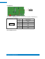
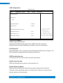
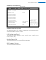
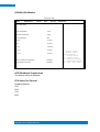
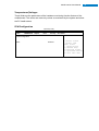
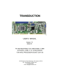
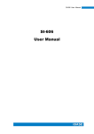
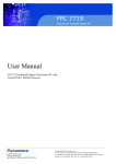
INOSP Series User Manual INOSP series User Manual Revision 2 Release Date V0.1 2014/02/12 V0.2 2014/03/20 V0.3 2014/05/21 Copyright © 2013 All Rights Reserved. 2 INOSP series User Manual Copyright © 2013 All Rights Reserved. No part of this manual, including the products and software described in it, may be reproduced, transmitted, transcribed, stored in a retrieval system, or translated into any language in any form or by any means, except documentation kept by the purchaser for backup purposes, without the express written permission of the authors. Products and corporate names mentioned in this manual may or may not be registered trademarks or copyrights of their respective companies, and are used for identification purposes only. All trademarks are the property of their respective owners. Every effort has been made to ensure that the contents of this manual are correct and up to date. However, the manufacturer makes no guarantee regarding the accuracy of its contents, and reserves the right to make changes without prior notice. i INOSP series User Manual ii Table of Contents Safety Information ..................................................................................................iii Setting up your system ....................................................................................................... iii Care during use ................................................................................................................... iv Acknowledgments ............................................................................................................... v CHAPTER 1 INTRODUCTION .................................................................................... 1 1.1 General Description ....................................................................................................... 1 1.2 System Specification ...................................................................................................... 2 1.2.1 Hardware Specifications ............................................................................................. 2 1.2.2 Dimensions ................................................................................................................. 3 1.2.3 I/O View ...................................................................................................................... 4 1.3 Packing List ..................................................................................................................... 5 1.3.1 Standard accessory ..................................................................................................... 5 1.3.2 Optional set 1 (with general power adaptor) ............................................................. 5 1.3.3 Optional set 2 (with IP65 I/O cover) ........................................................................... 5 1.3.4 Optional set 3 (with IP65 power adaptor) .................................................................. 6 1.4 Installation ..................................................................................................................... 7 1.4.1 Installing CFast ............................................................................................................ 7 1.4.2 Installing optional I/O cover ....................................................................................... 8 CHAPTER 2 MOTHERBOARD INTRODUCTION .......................................................... 9 2.1 Introduction ................................................................................................................... 9 2.2 Setting Jumpers............................................................................................................ 12 CHAPTER 3 BIOS SETUP .........................................................................................18 3.1 BIOS Introduction......................................................................................................... 18 3.2 BIOS Setup.................................................................................................................... 18 3.3 Advanced Settings ........................................................................................................ 19 3.4 Chipset Settings............................................................................................................ 29 CHAPTER 4 DRIVERS INSTALLATION .......................................................................41 4.1 Intel Chipset Software Installation Utility ................................................................... 41 4.2 VGA Drivers Installation ............................................................................................... 43 4.3 Realtek HD Audio Driver Installation ........................................................................... 45 4.4 Realtek LAN Controller Drivers Installation ................................................................. 47 Appendix ...............................................................................................................49 A. SSPA-24 IP65 stainless steel power adaptor ................................................................. 49 iii Safety Information Your INOSP series is designed and tested to meet the latest standards of safety for information technology equipment. However, to ensure your safety, it is important that you read the following safety instructions Setting up your system Read and follow all instructions in the documentation before you operate your system. Do not use this product near water. Set up the system on a stable surface. Do not secure the system on any unstable plane. Do not place this product on an unstable cart, stand, or table. The product may fall, causing serious damage to the product. Slots and openings on the chassis are for ventilation. Do not block or cover these openings. Make sure you leave plenty of space around the system for ventilation. Never insert objects of any kind into the ventilation openings. This system should be operated from the type of power indicated on the marking label. If you are not sure of the type of power available, consult your dealer or local power company. Use this product in environments with ambient temperatures between 0˚C and 50˚C. If you use an extension cord, make sure that the total ampere rating of the devices plugged into the extension cord does not exceed its ampere rating. DO NOT LEAVE THIS EQUIPMENT IN AN ENVIRONMENT WHERE THESTORAGE TEMPERATURE MAY GO BELOW -20° C OR ABOVE 60° C. THIS COULD DAMAGE THE EQUIPMENT. THE EQUIPMENT SHOULD BE IN A CONTROLLED ENVIRONMENT. Copyright © 2013 All Rights Reserved. INOSP series User Manual Care during use Do not walk on the power cord or allow anything to rest on it. Do not spill water or any other liquids on your system. When the system is turned off, a small amount of electrical current still flows. Always unplug all power, and network cables from the power outlets before cleaning the system. If you encounter the following technical problems with the product, unplug the power cord and contact a qualified service technician or your retailer. The power cord or plug is damaged. Liquid has been spilled into the system. The system does not function properly even if you follow the operating instructions. The system was dropped or the cabinet is damaged. Lithium-Ion Battery Warning CAUTION: Danger of explosion if battery is incorrectly replaced. Replace only with the same or equivalent type recommended by the manufacturer. Dispose of used batteries according to the manufacturer’s instructions. NO DISASSEMBLY The warranty does not apply to the products that have been disassembled by users. WARNING HAZARDOUS MOVING PARTS KEEP FINGERS AND OTHER BODY PARTS AWAY iv v Acknowledgments AMI is a registered trademark of AMI Software International, Inc. AMD and ATI are registered trademarks of AMD Corporation. Microsoft Windows is a registered trademark of Microsoft Corporation. FINTEK is a registered trademark of FINTEK Electronics Corporation. REALTEK is a registered trademark of REALTEK Electronics Corporation. All other product names or trademarks are properties of their respective owners. Copyright © 2013 All Rights Reserved. Left Empty for your notes INOSP series User Manual CHAPTER 1 INTRODUCTION 1.1 General Description INOSP series, a stainless steel panel PC, utilizes the dual-core 1.86GHz Intel® Atom™ Processor D2550 and Intel® NM10 chipset providing high computing performance and low power consumption. It includes 15 and 19 inch size. The fanless INOSP series operates silently and reliably in harsh environments. It comes with two SO-DIMM slots to accommodate up to 4GB of DDR3 1033/1066MHz system memory and one 2.5” SATA HDD and external CFast slot for data storage. It has two Gigabit Ethernet, an isolated RS-232/422/485 port, as well as an overload protected 2-in/2-out GPIO feature. The unit is equipped with 5-side IP65 protection. The optional IP65 compliant I/O cover has special M12 waterproof connectors and cables and is available in backward or downward orientation depending on the need of the customer. The INOSP series supports a wide range 12V~36V DC power input with optional 24V DC IP65 stainless steel power adaptor, which makes it ideal for food, livestock, chemical, mining, petro and factory automation or any other industrial applications. INOSP series overview 1 INOSP series User Manual 1.2 System Specification 1.2.1 Hardware Specifications Model Name INOSP-151-RE System Mainboard IB809 CPU Intel® AtomTM Processor D2550 (1M Cache, 1.86 GHz) Chipset Intel® NM10 PCH Memory 2 x DDR3-1033 /1066 SO-DIMM, up to 4GB I/O Interface 2 x USB 2.0 (USB Host. A-Type) 1 x isolated RS-232/422/485, COM1 1 x RS-232, COM3 1 x speaker-out microjack 1 x Mic-in microjack 2 x Gigabit LAN (RJ45) 1 x 6 pins terminal block GPIO 2in/2out/5VCC/Ground 1 x 3pin DC power connector 1 x Power on/off rock switch 1 x power on LED 1 x 2.5” SATA2 1 x external CFast Storage INOSP-191-RE Expansion Slots None Power Supply 12~36V Wide Range DC input LCD Size 15” TFT LCD 19” TFT LCD LCD Color 16.2M 16.7M LCD Resolution 1024 x 768 1280 x 1024 LCD Brightness 500 350 LCD View Angle (H°/V°) 160/160 170/160 Backlight MTBF 50,000 hrs Touch Screen Resistive Touch Screen Construction 304 stainless steel/ 316 stainless steel as option Mounting VESA mount, 100mm x 100mm Dimensions (W)x(D)x(H) mm 425 x 330 x 60 Operating Temperature 0°C~ 50°C( With SSD/CFast)/ 0°C~ 40°C(with HDD) Storage Temperature -20°C ~ 60°C Relative Humidity 10%~90% (non-condensing) Protection Class IP65 (except I/O side; Waterproof I/O cover with M12 connector is optional) ‧This specification is subject to change without prior notice. 470 x 388 x 60 2 3 1.2.2 Dimensions INOSP-151-RE INOSP-191-RE Copyright © 2013 All Rights Reserved. INOSP series User Manual 1.2.3 I/O View 4 5 1.3 Packing List 1.3.1 Standard accessory Part No. Description Quantity 1 Terminal Block 1 pc 1.3.2 Optional set 1 (with general power adaptor) Part No. Description Quantity 1 Terminal Block 1 pc 2 84W Adaptor for option (P/N: A005PS084W0050000P) 3 Power Cord for option 1 pc 1 pc 1.3.3 Optional set 2 (with IP65 I/O cover) Part No. 1 Description Downward direction cover (P/N: A028COVER191D0000P) Quantity 1 pc or Backward direction cover (P/N: A028COVER191B0000P) 2 External USB cable (P/N: A012CB01190101000P) 1 pc 3 External LAN cable (P/N: A012CB01200101000P) 1 pc 4 External COM cable (P/N: A012CB01210101000P) 1 pc 5 External Power cable (P/N: C501PW35203A21000P) 1 pc Copyright © 2013 All Rights Reserved. INOSP series User Manual 6 1.3.4 Optional set 3 (with IP65 power adaptor) Part No. 1 Description Downward direction cover (P/N: A028COVER191D0000P) Quantity 1 pc or Backward direction cover (P/N: A028COVER191B0000P) 2 External USB cable (P/N: A012CB01190101000P) 1 pc 3 External LAN cable (P/N: A012CB01200101000P) 1 pc 4 External COM cable (P/N: A012CB01210101000P) 1 pc 5 SSPA-24 stainless steel adaptor w/ external cables 191D Downward Direction I/O Cover 1 pc 191B Backward Direction I/O Cover SSPA-24 24VDC IP65 Stainless Steel Power Adaptor 7 1.4 Installation 1.4.1 Installing CFast 1. Loosen two screws and then replace the CFAST module. Copyright © 2013 All Rights Reserved. INOSP series User Manual 1.4.2 Installing optional I/O cover 1. Connect these I/O port cables. 2. Arrange the cables and push in with the I/O cover as shown. 3. Tighten the 10 screws as in the picture. 8 9 CHAPTER 2 MOTHERBOARD INTRODUCTION 2.1 Introduction The IB809 motherboard is based on the Intel® Atom Cedar Trail chipset. The Cedar Trail is a platform that uses the Intel Cedar Trail-D and Intel NM10 Express Chipset family in the desktop platforms. Below are the detailed specifications. Specifications – Mainboard Product Name Form Factor CPU Type CPU Speed Cache CPU Socket Chipset BIOS Memory LVDS Graph LAN USB 1. 2. 3. 4. Serial ATA Ports Audio LPC I/O - IB809 Customized Intel® Cedar View Processor, Atom D2550 2 core 10w TDP Package = FCBGA Type[ 22 mm x 22 mm] 1.86GHz 1MB L2 Package = FCBGA Type[ 22 mm x 22 mm] Intel® “Tiger Point” NM10 PCH, CG82NM10 [TDP = 2.1W, 130nm] Package = BGA360, 17mm x 17 mm AMI BIOS, support ACPI Function Intel® Atom TM on-die memory controller supporting up to 4GB/2GB each slot Two DDR3-1066 SO-DIMM socket [Horizontal type], Non-ECC, Unbuffered, 1.5V 2 x DF13 20p 24-bit Single/Dual channels LVDS interface via NXP PTN3460 from eDP VGA x 1 2x Realtek 8111G as 1st LAN and 2 nd LAN Intel® NM10 PCH integrated USB 2.0 host controller: 4 USB 2.0 type A ports in the rear side 1 port for onboard MiniPCIe 2 port onboard pin header 1 port for Touch Intel® NM10 PCH built-in SATA controller, Supports 2 x SATAII Intel® NM10 PCH built-in HD Audio controller + Realtek ALC269Q-VC2-GR Codec w/class-D speaker amplifier (2W per channel @ 5V power supply) support 2-channel audio out + amp F81866AD-I (128-pin LQFP [14mm x 14 mm]) COM #1 (RS232/422/485) RS-485 with AFC COM #2 (RS232/422/485) RS-485 with AFC COM #3 (RS232 only, supports ring-in with power @500 mA, z jumper selectable for 5V or 12V) COM #4 (RS232 only) pin header COM #5 (RS-232 for touch) [Hardware Monitor] 2 x Thermal inputs 2 x Voltage monitoring 1 x Smart fan DC mode Copyright © 2013 All Rights Reserved. INOSP series User Manual Digital IO - Expansion Slots Edge Connector On Board Headers/ Connectors 4 GPIO (2in/2out), 1 x 5V Vcc and 1 Ground [thru edge connector @ 1x6 pins Terminal block type], not TTL with circuit protection 5V Vcc has count-current protection 4 GPIO(2in/2out) and Ground (header), not TTL with circuit protection 1 x Mini PCI-e socket x 1, Full/Half-sized type 1 x CFast GPIO (2in/2out)/VCC/Ground 1x6 pins terminal block RJ45 x 2 for GbE LAN, 2 connector for 2 port DB9 x 1 for COM1 (isolated) DB9 x 1 for COM3 USB 2.0 connector x 4 for USB1~4, 2 connectors for 4 ports 3 pins terminal block (+/G/-) for power input Line out microjack x 1 Mic-in microjack x 1 CFast socket x 1 Power LED SMD type, power on is green else no light 2 ports x SATA II, SATA #2 shared CFast via NXP CBTL02043ABQ switch 4 pins power connector x 2 for SATA HDD 1 x DF-11 10 pin header for COM2 1 x DF-11 10 pin heard for COM4 1 x DF-11 10 pin header for VGA 1x8 pins DF-11 header x 1 for 2 ports USB 2.0 2x DF20G-20DP connector for 24-bit Single/Dual channel LVDS 2x5 pins headers x 1 for LPC (Debug purpose only) Mini PCI-e(1x) connector x 1 [Full/Half-sized] 1 x 5 2.0mm pins box header connector for 5 wire touch 1 x 4 2.5mm pins connector for L&R speaker out 1 x 7 pins box header for LCD backlight control 12V(1.5A)/12V(1.5A)/PWM/Backlight0~5V(500mA)/3.3V(500mA)/GN/ GN) 1 x 5 pins box header for smart battery (RST/EXTSMI/Ground/DATA/CLK) 1 x 5 pins box header for GPIO, 2in/2out/Ground, not TTL 1 x 2 pins connector for RTC battery 1 x 3 pins connector for system smart fan DC type 1 x 8 pins header for Power on-off/reset/Power LED/HDD LED Yes (256 segments, 0, 1, 2…255 sec/min) Watchdog Timer Power Connector +12V(-10%)~+36V(+5%) DC-input RoHS Yes Board Size Customized Golden Finger PCIe x 16 golden finger for PCI (124P) and PCIe x1 (36P) signal Please follow IB806 define, but remove USB and COM signal Touch controller Onboard Penmount 6000 USB/RS-232 selectable by jumper, default RS-232 Others 1. CPU & NM10 PCH are located at back side 2. No chemical capacitor on board 3. -20~60 °C Operating temperature 10 11 Board Dimensions Copyright © 2013 All Rights Reserved. INOSP series User Manual 12 2.2 Setting Jumpers Warning: INOSP series is a waterproof product. It is not advisable to reconfigure the jumpers inside. Otherwise, please specify the required settings upon ordering. Jumpers are used on IB809 to select various settings and features according to your needs and applications. Contact your supplier if you have doubts about the best configuration for your needs. The following lists the jumpers and connectors on IB809. Jumper Locations on IB809 JP6: COM3 RS232 RI/+5V/+12V Setting JP6 1 3 5 2 4 6 2 6 1 5 Setting Function Pin 1-3 - Short/Closed +12V Pin 3-4 - Short/Closed RI* Pin 3-5 - Short/Closed +5V Note: The suggested setting is RI, with Max. current lower than 0.5A. 13 Connector Locations on IB809 CN1: DC-IN +12~36V Connector 1X3_5.0mm_Male_Terminal (DINKLE 5EHDRM-03P) Mating: DINKLE 5ESDVM-03P Pin # Signal Name 1 + 2 G 3 - CN2: Isolate COM1/RS232/422/485 Pin # Signal Name RS-232 RS-422 RS-485 1 DCD TX- DATA- 2 RX TX+ DATA+ 3 TX RX+ NC 4 DTR RX- NC 5 Ground Ground Ground 6 DSR NC NC 7 RTS NC NC 8 CTS NC NC 9 RI NC NC Copyright © 2013 All Rights Reserved. INOSP series User Manual CN3: Digital I/O 1X6_3.5mm_Male_Terminal (DINKLE ECH350RM-06P) Mating: DINKLE EC350VM-06P Pin # Signal Name 1 OUT0 2 OUT1 3 IN0 4 IN1 5 +5V/0.5A 6 GND CN4: COM3 RS232 Serial Port Pin # Signal Name 1 DCD 2 RX 3 TX 4 DTR 5 Ground 6 DSR 7 RTS 8 CTS 9 RI*/+5V/+12V Note: Pin 9 supports RI/+5V/+12V function set by JP6. CN5, CN6: USB2.0 Connectors Pin # Signal Name 1 VCC 2 DATA- 3 DATA+ 4 Ground 14 15 CN7, CN8: Gigabit LAN Connectors (Realtek RTL8111G-CG) Pin # Signal Name 1 MDI0+ 2 MDI0- 3 MDI1+ 4 MDI1- 5 MDI2+ 6 MDI2- 7 MDI3+ 8 MDI3- CN9: CFAST Connector Remarks: Signal is shared with SATA connector (J6) CN10: HD Audio Line-out Connector CN11: HD Audio Microphone Connector J17: COM4 RS232 Serial Port 1 9 2 10 2 10 2X5_2.0mm_Straight_Male_DF11 (Haoguo DF11-10S-PA66H compatible Hirose DF11-10DP-2DSA (08)) Mating connector: Hirose DF11-10DS-2C 1 9 2 10 Signal Name Pin # Pin # Signal Name DCD 1 2 RXD TXD 3 4 DTR Ground 5 6 DSR RTS 7 8 CTS RI 9 10 N.C. Copyright © 2013 All Rights Reserved. INOSP series User Manual J18: Isolate COM2 RS232/422/485 1 9 2 10 2 10 2X5_2.0mm_Straight_Male_DF11 (Haoguo DF11-10S-PA66H compatible Hirose DF11-10DP-2DSA (08)) Mating connector: Hirose DF11-10DS-2C Pin # 1 9 2 10 Signal Name RS-232 RS-422 RS-485 1 DCD TX- DATA- 2 RX TX+ DATA+ 3 TX RX+ NC 4 DTR RX- NC 5 Ground Ground Ground 6 DSR NC NC 7 RTS NC NC 8 CTS NC NC 9 RI NC NC 10 NC NC NC 16 17 J19: Digital I/O 1 6 1X5_2.0mm_Straight_Male (E-CALL_0110-161-060 compatible JST B6B-PH-K-S) Mating connector: JST PHR-6 6 1 LED2: POWER LED (Green) Copyright © 2013 All Rights Reserved. Pin # Signal Name 1 OUT2 2 OUT3 3 IN2 4 IN3 5 +5V/0.5A 6 GND INOSP series User Manual 18 CHAPTER 3 BIOS SETUP 3.1 BIOS Introduction The BIOS (Basic Input/Output System) installed in your computer system’s ROM supports Intel processors. The BIOS provides critical low-level support for a standard device such as disk drives, serial ports and parallel ports. It also password protection as well as special support for detailed fine-tuning of the chipset controlling the entire system. 3.2 BIOS Setup The BIOS provides a Setup utility program for specifying the system configurations and settings. The BIOS ROM of the system stores the Setup utility. When you turn on the computer, the BIOS is immediately activated. Pressing the <Del> key immediately allows you to enter the Setup utility. If you are a little bit late pressing the <Del> key, POST (Power On Self Test) will continue with its test routines, thus preventing you from invoking the Setup. If you still wish to enter Setup, restart the system by pressing the ”Reset” button or simulta neously pressing the <Ctrl>, <Alt> and <Delete> keys. You can also restart by turning the system Off and back On again. The following message will appear on the screen: Press <DEL> to Enter Setup In general, you press the arrow keys to highlight items, <Enter> to select, the <PgUp> and <PgDn> keys to change entries, <F1> for help and <Esc> to quit. When you enter the Setup utility, the Main Menu screen will appear on the screen. The Main Menu allows you to select from various setup functions and exit choices. Warning: It is strongly recommended that you avoid making any changes to the chipset defaults. These defaults have been carefully chosen by both AMI and your system manufacturer to provide the absolute maximum performance and reliability. Changing the defaults could cause the system to become unstable and crash in some cases. 19 3.3 Advanced Settings This section allows you to configure and improve your system and allows you to set up some system features according to your preference. Aptio Setup Utility Main Advanced Chipset Boot Security Save & Exit Legacy OpROM Support Launch PXE OpROM Disabled Launch Storage OpROM Enabled ► PCI Subsystem Settings ► ACPI Settings ► Wake up event setting ► CPU Configuration ► NXP3460 Configuration ► SATA Configuration ► USB Configuration ► F81866 Super IO Configuration ► F81866 H/W Monitor ► PPM Configuration → ←Select Screen ↑↓Select Item Enter: Select +- Change Field F1: General Help F2: Previous Values F3: Optimized Default F4: Save ESC: Exit Launch PXE OpROM Enable or Disable Boot Option for Legacy Network Devices. Launch Storage OpROM Enable or Disable Boot Option for Legacy Mass Storage Devices with Option ROM. Copyright © 2013 All Rights Reserved. INOSP series User Manual PCI Subsystem Settings Aptio Setup Utility Main Advanced PCI Bus Driver Version PCI ROM Priority Chipset Boot Security Save & Exit V 2.05.01 Legacy ROM PCI Common Settings PCI Latency Timer 32 PCI Bus Clocks VGA Palette Snoop Disabled PERR# Generation Disabled SERR# Generation Disabled → ←Select Screen ↑↓Select Item Enter: Select +- Change Field F1: General Help F2: Previous Values F3: Optimized Default F4: Save ESC: Exit PCI ROM Priority In case of multiple Option ROMs (Legacy and EFI Compatible), specifies what PCI Option ROM to launch. PCI Latency Timer Value to be programmed into PCI Latency Timer Register. VGA Palette Snoop Enables or Disables VGA Palette Registers Snooping. PERR# Generation Enables or Disables PCI Device to Generate PERR#. SERR# Generation Enables or Disables PCI Device to Generate SERR#. 20 21 ACPI Settings Aptio Setup Utility Main Advanced Chipset Enable ACPI Auto Configuration Boot Security Save & Exit Disabled → ←Select Screen Enable Hibernation Enabled ACPI Sleep State S1 (CPU Stop Clock) S3 Video Report Disabled ↑↓Select Item Enter: Select +- Change Field F1: General Help F2: Previous Values F3: Optimized Default F4: Save ESC: Exit Enabled ACPI Auto Configuration Enables or Disables BIOS ACPI Auto Configuration. Enable Hibernation Enables or Disables System ability to Hibernate (OS/S4 Sleep State). This option may be not effective with some OS. ACPI Sleep State Select the highest ACPI sleep state the system will enter, when the SUSPEND button is pressed. S3 Video Report The default setting is Disabled. Copyright © 2013 All Rights Reserved. INOSP series User Manual Wake up event settings Aptio Setup Utility Main Advanced Chipset Wake system with Fixed Time Boot Security Save & Exi t Disabled Wake up hour 0 Wake up minute 0 Wake up second 0 Wake up by Ring Disabled Wake up by PCIE WAKE# Disabled → ←Select Screen ↑↓Select Item Enter: Select +- Change Field F1: General Help F2: Previous Values F3: Optimized Default F4: Save ESC: Exit Wake system with Fixed Time Enables or Disables System wake on alarm event. When enabled, System will wake on the hr::min:: sec specified. Wake on Ring The options are Disabled and Enabled. Wake on PCIE PME The options are Disabled and Enabled. Remarks: If Wake on LAN is to be supported, this option should be enabled. 22 23 CPU Configuration This section shows the CPU configuration parameters. Aptio Setup Utility Main Advanced Chipset Boot Security Save & Exit CPU Configuration Processor Type Intel(R) Atom(TM) CPU EMT64 Supported Processor Speed 1865 MHz System Bus Speed 533 MHz Ratio Status 14 Actual Ratio 14 System Bus Speed 533 MHz Processor Stepping 30661 Microcode Revision 269 L1 Cache RAM 2x56 k L2 Cache RAM 2x512 k Processor Core Dual Hyper-Threading Supported Hyper-Threading Enabled Execute Disable Bit Enabled → ←Select Screen ↑↓Select Item Enter: Select +- Change Field F1: General Help F2: Previous Values F3: Optimized Default F4: Save ESC: Exit Hyper-threading Enabled for Windows XP and Linux (OS optimized for Hyper-Threading Technology) and Disabled for other OS (OS not optimized for Hyper-Threading Technology). When Disabled, only one thread per enabled core is enabled. Execute Disable Bit XD can prevent certain classes of malicious buffer overflow attacks when combined with a supporting OS (Windows Server 2003 SP1, Windows XP SP2, SuSE Linux 9.2, Re33dHat Enterprise 3 Update 3.) Copyright © 2013 All Rights Reserved. INOSP series User Manual NXP3460 Configuration Aptio Setup Utility Main Advanced Chipset Boot Security Save & Exit NXP3460 Configuration LCD Protocol 24bit(VESA), Single… Panel Type 1024 x 768 → ←Select Screen ↑↓Select Item Enter: Select +- Change Field F1: General Help F2: Previous Values F3: Optimized Default F4: Save ESC: Exit SATA Configuration Aptio Setup Utility Main Advanced Chipset Boot Security SATA Port0 Not Present SATA Port1 Not Present Save & Exit → ←Select Screen SATA Controller(s) Enabled Configure SATA as IDE SATA Controller(s) Enable / Disable Serial ATA Controller. Configure SATA as (1) IDE Mode. (2) AHCI Mode. ↑↓Select Item Enter: Select +- Change Field F1: General Help F2: Previous Values F3: Optimized Default F4: Save ESC: Exit 24 25 USB Configuration Aptio Setup Utility Main Advanced Chipset Boot Security Save & Exit USB Configuration USB Devices: None Legacy USB Support Enabled EHCI Hand-off Enabled → ←Select Screen USB hardware delays and time-outs: USB Transfer time-out 20 sec Device reset tine-out 20 sec Device power-up delay AUTO ↑↓Select Item Enter: Select +- Change Field F1: General Help F2: Previous Values F3: Optimized Default F4: Save ESC: Exit Legacy USB Support Enables Legacy USB support. AUTO option disables legacy support if no USB devices are connected. DISABLE option will keep USB devices available only for EFI applications. EHCI Hand-off Enabled/Disabled. This is a workaround for OSes without EHCI hand-off support. The EHCI ownership change should be claimed by EHCI driver. USB Transfer time-out The time-out value for Control, Bulk, and Interrupt transfers. Device reset tine-out USB mass Storage device start Unit command time-out. Device power-up delay Maximum time the device will take before it properly reports itself to the Host Controller. ‘Auto’ uses default value: for a Root port it is 100ms, for a Hub port the delay is taken from Hub descriptor. Copyright © 2013 All Rights Reserved. INOSP series User Manual F81866 Super IO Configuration Aptio Setup Utility Main Advanced Chipset Boot Security Save & Exit F81866 Super IO Configuration F81866 Super IO Chip F81866 ► Serial Port 0 Configuration ► Serial Port 1 Configuration ► Serial Port 2 Configuration ► Serial Port 3 Configuration → ←Select Screen ► Serial Port 4 Configuration LVDS Backlight Level Control Level-1 (Maximum) Backlight Output Mode PWM Mode PWM Frequency Selection 220Hz ↑↓Select Item Enter: Select +- Change Field F1: General Help F2: Previous Values F3: Optimized Default F4: Save ESC: Exit F81866 Serial Port Configuration Set Parameters of Serial Ports. User can Enable/Disable the serial port and Select an optimal settings for the Super IO Device. LVDS Backlight Level Control The options are : Level-1 (Maximum) , Level-2 , Level-3 , Level-4 , Level-5 , Level-6 , Level-7 , Level-8 (~0V). Backlight Output Mode This provides PWM duty-cycle output or DAC voltage output. PWM Frequency Selection This provides 4 frequency Selection. 26 27 F81866 H/W Monitor Aptio Setup Utility Main Advanced Chipset Boot Security Save & Exit Pc Health Status CPU temperature +39 C System temperature +28 C CPU Fan Speed N/A Vcore +1.208 V +5V +5.087 V +12V +12.320 V +1.5V +1.528 V +3.3V +3.456 V ACPI Shutdown Temperature Disabled CPU Smart Fan Control Disabled ACPI Shutdown Temperature The default setting is Disabled. CPU Smart Fan Control Disabled (default) 50 C 60 C 70 C 80 C Copyright © 2013 All Rights Reserved. → Select Screen ↑↓Select Item Enter: Select +- Change Field F1: General Help F2: Previous Values F3: Optimized Default F4: Save ESC: Exit INOSP series User Manual Temperatures/Voltages These fields are the parameters of the hardware monitoring function feature of the motherboard. The values are read-only values as monitored by the system and show the PC health status. PPM Configuration Aptio Setup Utility Main Advanced Chipset Boot Security Save & Exit PPM Configuration EIST Enabled → ←Select Screen ↑↓Select Item Enter: Select +- Change Field F1: General Help F2: Previous Values F3: Optimized Default F4: Save ESC: Exit 28 29 3.4 Chipset Settings This section allows you to configure and improve your system and allows you to set up some system features according to your preference. Aptio Setup Utility Main Advanced Chipset Boot Security ► Host Bridge ► South Bridge Host Bridge This item shows the Host Bridge Parameters. South Bridge This item shows the South Bridge Parameters. Copyright © 2013 All Rights Reserved. Save & Exit → ←Select Screen ↑↓Select Item Enter: Select +- Change Field F1: General Help F2: Previous Values F3: Optimized Default F4: Save ESC: Exit INOSP series User Manual Host Bridge This section allows you to configure the Host Bridge Chipset. Aptio Setup Utility Main Advanced Chipset Boot Security Save & Exit ► Memory Frequency and Timing ► Intel IGD Configuration → ←Select Screen ************Memory Information************ Memory Frequency 1067 MHz(DDR3) Total Memory 2048 MB DIMM#1 2048 MB ↑↓Select Item Enter: Select +- Change Field F1: General Help F2: Previous Values F3: Optimized Default F4: Save ESC: Exit Memory Frequency and Timing Aptio Setup Utility Main Advanced Chipset Boot Security Save & Exit Memory Frequency and Timing → ←Select Screen MRC Fast Boot Disabled MRC Fast Boot The options are Disabled and Enabled. ↑↓Select Item Enter: Select +- Change Field F1: General Help F2: Previous Values F3: Optimized Default F4: Save ESC: Exit 30 31 Intel IGD Configuration Aptio Setup Utility Main Advanced Chipset Boot Security Save & Exit Intel IGD Configuration Active LFP Int-LVDS → ←Select Screen ↑↓Select Item Enter: Select +- Change Field F1: General Help F2: Previous Values F3: Optimized Default F4: Save & Exit ESC: Exit Active LFP Select the Active LFP Configuration. No LVDS: VBIOS does not enable LVDS. Int-LVDS: VBIOS enables LVDS driver by Integrated encoder. Copyright © 2013 All Rights Reserved. INOSP series User Manual South Bridge This section allows you to configure the South Bridge Chipset. Aptio Setup Utility Main Advanced Chipset Boot Security Save & Exit ► TPT Device ► PCI Express Root Port0 ► PCI Express Root Port1 ► PCI Express Root Port2 ► PCI Express Root Port3 DMI Link ASPM Control Enabled PCI-Exp. High Priority Port Disabled High Precision Event Timer Configuration High Precision Timer Enabled SLP_SP4 Assertion Width 1-2 Seconds Restore AC Power Loss Power off → ←Select Screen ↑↓Select Item Enter: Select +- Change Field F1: General Help F2: Previous Values F3: Optimized Default F4: Save ESC: Exit DMI Clink ASPM Control The control of Active State Power Management on both NB side and SB side of the DMI Link. PCI-Exp. High Priority Port The options are Disabled, Port1, Port2, Port3, and Port4. High Precision Event Timer Configuration Enable/or Disable the High Precision Event Timer. SLP_S4 Assertion Stretch Enable Select a minimum assertion width of the SLP_S4# signal. 32 33 TPT Device Aptio Setup Utility Main Adva Chipset Boot Security Azalia Controller HD Audio UHCI #1 (port 0 and 1) Enabled UHCI #2 (port 2 and 3) Enabled UHCI #3 (port 4 and 5) Enabled UHCI #4 (port 6 and 7) Enabled USB 2.0(UHCI) Support Enabled Save & Exit → ←Select Screen ↑↓ Select Item Enter: Select +- Change Field F1: General Help F2: Previous Values F3: Optimized Default F4: Save ESC: Exit PCI Express Root Port0 Aptio Setup Utility Main Advanced Chipset Boot Security PCI Express Port 0 Enabled Port 0 IOxAPIC Disabled Automatic ASPM Manual ASPM L0s Root Port Only ASPM L1 Enabled Copyright © 2013 All Rights Reserved. Save & Exit → ←Select Screen ↑↓ Select Item Enter: Select +- Change Field F1: General Help F2: Previous Values F3: Optimized Default F4: Save ESC: Exit INOSP series User Manual PCI Express Root Port1 Aptio Setup Utility Main Advanced Chipset PCI Express Port 1 Boot Security Save & Exit Auto Port 0 IOxAPIC Disabled Automatic ASPM Manual ASPM L0s Root Port Only ASPM L1 Enabled → ←Select Screen ↑↓Select Item Enter: Select +- Change Field F1: General Help F2: Previous Values F3: Optimized Default F4: Save ESC: Exit PCI Express Root Port2 Aptio Setup Utility Main Advanced PCI Express Port 2 Port 0 IOxAPIC Chipset Boot Security Save & Exit Auto Disabled Automatic ASPM Manual ASPM L0s Disabled ASPM L1 Disabled → ←Select Screen ↑↓ Select Item Enter: Select +- Change Field F1: General Help F2: Previous Values F3: Optimized Default F4: Save ESC: Exit 34 35 PCI Express Root Port3 Aptio Setup Utility Main Advanced Chipset PCI Express Port 3 Port 0 IOxAPIC Boot Save & Exit Auto Disabled Automatic ASPM Manual ASPM L0s Disabled ASPM L1 Disabled Copyright © 2013 All Rights Reserved. Security → ←Select Screen ↑↓Select Item Enter: Select +- Change Field F1: General Help F2: Previous Values F3: Optimized Default F4: Save ESC: Exit INOSP series User Manual 36 Boot Settings Aptio Setup Utility Main Advanced Chipset Boot Security Save & Exit Boot Configuration Setup Prompt Timeout 1 Bootup NumLock State On Quiet Boot Disabled Fast Boot Disabled CSM16 Module Version 07.68 GateA20 Active Upon Request Option ROM Messages Force BIOS Interrupt 19 Canture Disabled Boot Option Priorities → ←Select Screen ↑↓Select Item Enter: Select +- Change Field F1: General Help F2: Previous Values F3: Optimized Default F4: Save ESC: Exit Setup Prompt Timeout Number of seconds to wait for setup activation key. 65535(0xFFFF) means indefinite waiting. Bootup NumLock State Select the keyboard NumLock state. Quiet Boot Enables/Disables Quiet Boot option. Fast Boot Enables/Disables boot with initialization of a minimal set of devices required to launch active boot option. Has no effect for BBS boot options. 37 GateA20 Active UPON REQUEST – GA20 can be disabled using BIOS services. ALWAYS– do not allow disabling GA20; this option is useful when any RT code is executed above 1MB. Option ROM Messages Set display mode for Option ROM. Options: Force BIOS and Keep Current. Interrupt 19 Capture Enable: Allows Option ROMs to trap Int 19. Boot Option Priorities Sets the system boot order Copyright © 2013 All Rights Reserved. INOSP series User Manual Security Settings This section allows you to configure and improve your system and allows you to set up some system features according to your preference. Aptio Setup Utility Main Advanced Chipset Boot Security Save & Exit Password Description If ONLY the Administrator’s password is set, then this only limits access to Setup and is only asked for when entering Setup. If ONLY the User’s password is set, then this is a power on password and must be entered to boot or enter Setup. In Setup the User will have Administrator rights Administrator Password User Password Administrator Password Set Setup Administrator Password. User Password Set User Password. → ←Select Screen ↑↓Select Item Enter: Select +- Change Field F1: General Help F2: Previous Values F3: Optimized Default F4: Save ESC: Exit 38 39 Save & Exit Settings Aptio Setup Utility Main Advanced Chipset Boot Security Save & Exit Save Changes and Exit Discard Changes and Exit Save Changes and Reset Discard Changes and Reset Save Options Save Changes Discard Changes Restore Defaults Save as User Defaults Restore User Defaults → ← Select Screen ↑↓ Select Item Enter: Select +- Change Field F1: General Help F2: Previous Values F3: Optimized Default F4: Save ESC: Exit Boot Override Save Changes and Exit Exit system setup after saving the changes. Discard Changes and Exit Exit system setup without saving any changes. Save Changes and Reset Reset the system after saving the changes. Discard Changes and Reset Reset system setup without saving any changes. Save Changes Save Changes done so far to any of the setup options. Discard Changes Discard Changes done so far to any of the setup options. Copyright © 2013 All Rights Reserved. INOSP series User Manual Restore Defaults Restore/Load Defaults values for all the setup options. Save as User Defaults Save the changes done so far as User Defaults. Restore User Defaults Restore the User Defaults to all the setup options. Boot Override Pressing ENTER causes the system to enter the OS. Launch EFI Shell from filesystem device Attempts to Launch EFI Shell application (Shellx64.efi) from one of the available filesystem devices. 40 41 CHAPTER 4 DRIVERS INSTALLATION This section describes the installation procedures for software and drivers. The software and drivers are included with the motherboard IMPORTANT NOTE: After installing your Windows operating system, you must install first the Intel Chipset Software Installation Utility before proceeding with the drivers installation. 4.1 Intel Chipset Software Installation Utility The Intel Chipset Drivers should be installed first before the software drivers to enable Plug & Play INF support for Intel chipset components. Follow the instructions below to complete the installation. 1. Insert the disc that comes with the board. Click Intel and then Intel(R) Cedar Trail Chipset Drivers. 2. Click Intel(R) Chipset Software Installation Utility. Copyright © 2013 All Rights Reserved. INOSP series User Manual 3. When the Welcome screen to the Intel® Chipset Device Software appears, click Next to continue. 4. Click Yes to accept the software license agreement and proceed with the installation process. 5. On the Readme File Information screen, click Next to continue the installation. 6. The Setup process is now complete. Click Finish to restart the computer and for changes to take effect. 42 43 4.2 VGA Drivers Installation 1. Insert the disc that comes with the board. Click Intel and then Intel(R) Cedar Trail Chipset Drivers. 2. Click Intel(R) Cedar Trail Graphics Driver. Copyright © 2013 All Rights Reserved. INOSP series User Manual 44 3. When the Welcome screen appears, click Next to continue. 4. Click Yes to to agree with the license agreement and continue the installation. 5. On the Readme File Information screen, click Next to continue the installation of the Intel® Graphics Media Accelerator Driver. 6. On Setup Progress screen, click Next to continue. 7. Setup complete. Click Finish to restart the computer and for changes to take effect. 45 4.3 Realtek HD Audio Driver Installation Follow the steps below to install the Realtek HD Audio Drivers. 1. Insert the disc that comes with the board. Click Intel and then Intel(R) Cedar Trail Chipset Drivers. 2. Click Realtek High Definition Audio Driver. Copyright © 2013 All Rights Reserved. INOSP series User Manual 46 3. On the Welcome to the InstallShield Wizard screen, click Next to proceed with and complete the installation process. 4. Restart the computer when prompted. 47 4.4 Realtek LAN Controller Drivers Installation Follow the steps below to install the Realtek LAN Drivers. 1. Insert the CD that comes with the board. Click LAN Card, and then Realtek Lan Controller Drivers. 2. Click Realtek RTL8111G LAN Drivers. Copyright © 2013 All Rights Reserved. INOSP series User Manual 3. When the welcome screen to InstallShield Wizard appears, click Next to start the installation. 4. When the InstallShieldWizard has finished installing the Realtek LAN drivers, click Finish. 48 49 Appendix A. SSPA-24 IP65 stainless steel power adaptor Optional 90~240V AC input, 24V DC output IP65 stainless steel power adaptor. Specification –SSPA-24 Edge I/O - M23 connector AC input - 4 pin M12 connector DC output (4 pin definition: +/-/G/earth ground) Power Power Module - AC/DC open frame Power Supply - 24V DC input Construction Chassis - 304 stainless steel / 316 stainless steel for option Mounting - Wall mount Protection Class - Total IP65 Environmental - Operating: 0°C~ 50°C (Max 80W at 50°C) - Storage: -40°C~85°C Humidity - 10%~90% (non-condensing) Regulation - RoHS Certification - CE/FCC class A Temperature Accessary - Wall Mount Kits - 1 x power cable M23/3P L=5m - 1 x power cable M12 4P L=2m - Power connector for U.S. regulation (option) - Power connector for EU regulation (option) - Power connector for Australian regulatory (option) Copyright © 2013 All Rights Reserved.