1
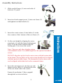
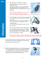
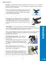
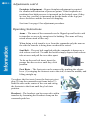
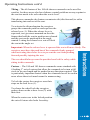
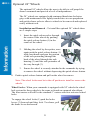
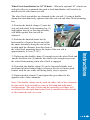
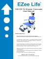
.....................................................................................................................
190/195 Tilt Shower Commode
User Manual
Limited Warranty:
EZee Life products carry a two year warranty against
manufacturing defects, faulty materials and workmanship only.
Any alterations, misuse, abuse, or accidental damage voids this
warranty. EZee Life reserves the right to replace or repair any
part that has become defective.
The warranty does not extend to consequential costs resulting
from the fault or defect of the product: freight and travel costs,
loss of earnings, or other expenses that one may incur.
Warranty is valid for the original purchaser only and the original
receipt must be
presented before any warranty options are considered. Please
also be prepared to
provide the date of purchase and serial number.
EZee Life™ Products
34 Futurity Gate, Unit # 15 Concord Ontario L4K 1S6
Specifications:
Frame Material – Aluminum
Tilt Range – 20°
Weight – 36 lbs (#190)
38 lbs (#195)
Rear wheels – 5” standard or optional 24”
Front Casters – 5”
Seat Width – 18” (#190) 20” (#195)
Seat Depth – 17”
Standard Seat Heights – 23.5” or 24.5” (adjustable)
Foot Rest Hanger Angle – 60°
Foot Rest Length – 14” to 20” (Infinite adjustment)
Back Height – 18”
Arm Height – 11” (from seat)
Arm Length – 13”
Arm Pad Length – 9 1/2”
Weight Capacity – 250 lbs (#190), 300 lbs (#195)
Features:
Molded seat, back & arm rest pads
Commode hole insert
Adjustable molded headrest
Flip back arms
Locking swivel casters
Adjustable height swing away footrests
Composite flip up foot plates
Side release seat belt
Calf Strap
Single lever tilt release
Strong tubular aluminum frame
Adjustable removable anti-tippers
2
Assembly Instructions
1. Slide seat belt loops (1) onto each side of
backrest (2) posts.
2. Insert two back support posts (1) into seat frame (2)
and tighten two hand wheels (3).
3. Insert four caster stems (1) into holes (2) in the
four corners of the bottom of the seat frame (3).
4. Set the seat height by aligning the caster
stem holes (1) with the desired adjustment
holes (2) in the frame and inserting the
locking pin (3) to secure the caster.
Note: There are only three height settings
with standard casters. For added height use the optional extended
casters
DO NOT align the top hole in the caster stem with the bottom hole
in the frame. The top hole on the caster stem should only be aligned
with the top hole in the frame. The bottom hole in the caster stem
can be aligned with either hole in the commode frame.
5. Insert the anti-tippers (1) into the two antitipper receiver tubes (2) located at the rear
of the seat frame above the casters.
Ensure the push pins (3) have popped
through the set receiver holes.
3
6. The adjustment is made by simply
depressing the anti-tipper push pin (1),
sliding the inner
anti-tipper tube (2) to the desired length,
aligning the push pin with the closest
adjustment hole (3) and allowing it to pop
through.
(The anti-tippers should be as close to the
floor as possible without catching on
doorway thresholds, changes in floor levels or other obstacles.)
7. To attach the foot rest (1) to the commode
lower the foot rest pivot plug (2) into the
top of the
front seat frame (3) with the foot plate (4)
off to the side of the commode. Then
swing the foot
rest to the forward position where it will
lock in place.
8. The foot plate height can be adjusted by
loosening the footrest clamp (1), sliding
the the foot plate extension tube (2) up or
down inside the foot rest hanger tube (3)
and re-tightening the clamp.
DO NOT extend the footplates past the MAX line (4) stamped into
the foot plate extension tubes. The MAX line should not be visible.
9. From the back of the commode slide the commode
pail into the pail support channels (1) located on
the bottom of the seat pan (2).
10. Install the adjustable head rest (1) by inserting and
vertical support tube (2) into the headrest bracket
(3) mounted on the commode push bar and then
insert the horizontal support tube (4) through the
end bracket (5) of the vertical tube (2).
4
Adjustments
Headrest – The headrest on this commode is referred to as an “X” headrest
and the smaller end of the “X” is at the bottom to support the neck where it
meets the back of the skull.
The arms of this style of headrest can be flexed in
or out as needed by simply pulling them apart or
squeezing them together to provide more control
or more freedom as needed.
The angle of the headrest can also be adjusted by
loosening the three allen screws (1) holding the
horizontal support tube (2), pivoting the head rest
to the desired position and re-tightening the allen
screws.
Anti-Tippers – The anti- tippers are required to prevent the
commode from tipping backwards when it is tilted back or when the
user is self-propelling with the optional 24” wheels.
They can be flipped up or removed when necessary to clear obstacles
but should be in place as often as possible to prevent accidental
tipping of the commode.
Tilt Mechanism Cables – The cables (1)
that allow the chair to tilt may over time
stretch. This
is normal and can be adjusted by loosing the
lock nut (2), turning the adjustment screw
(3) counter-clockwise and re-tightening the
lock nut.
When adjusted properly the distance
between the strut release lever (5) and the
cable anchor (6) should be 1”.
If the chair angle cannot be changed when
the tilt lever (4) is depressed the cause is
usually stretched cables. If the chair will not
lock at any angle the cables are likely adjusted too tight.
5
Adjustments cont'd
Footplate Adjustment – Proper footplate adjustment is required
for comfort and reduction of pressure points. If the footplates are
positioned too high pressure is increased on the buttock area; if they
are too low, pressure is increased on the the backs of the legs just
above the knees and the feet are left dangling.
See item 8 on page 4 for adjustment procedure.
Operating Instructions
Arms – The arms of the commode can be flipped up and back to aid
in transfers or access by caregivers for bathing. The arms will stay
raised when raised all the way.
When doing a side transfer to or from the commode only the arm on
the side the transfer is being done on should be raised.
Seat Belt – The seat belt supplied with the commode is known as a
side release seat belt. To undo the buckle simply depress both release
tabs at once and pull the two sides apart.
To do up the seat belt insert insert the
prongs into the receiver until they click
position.
into
Foot Rests – The foot rests can be removed by pushing the release
lever (1) swinging the footrests out to the side, or into the middle, and
lifting straight up.
To replace the foot rests, lower the foot rest pivot
plug (2) into the commode seat frame holes (3)
from the side on the center of the seat and swing
the footrests to the front until they lock into
position.
Headrest – The headrest can be removed to aid in
transfers by loosening the Headrest clamp on the
commode push bar.
6
Operating Instructions cont'd
Tilting – The tilt feature of the 190 tilt shower commode can be used for
comfort, for those users who have balance control problems or may squirm in
the seat too much to be safe when the seat is level.
This shower commode also features an anterior tilt (tilts forward) to aid in
transferring into and out of the seat.
To activate the tilt mechanism the caregiver
grasps the commode push bar and squeezes the
release lever (1). When the release lever is
squeezed, two gas struts mounted on the side
frames that hold the seat in position are released
and the seat can be positioned at the angle
wanted. Letting the release lever out will lock
the seat at the angle set.
Important: When the release lever is squeezed the seat will move freely. The
caregiver must have the push bar of the commode firmly grasped
when activating the release lever to prevent the seat from pitching
forward possibly injuring the user.
The user should always wear the provided seat belt for safety while
sitting in this commode.
Casters – The 180 and 185 shower commodes come standard with
4 locking 5” swivel casters that allow the commode to be turn a full
circle in its own length and be pushed in any direction required. This
is particularly important feature when the commode has to be used in
areas where there isn't much room for manoeuvring.
To lock the casters the caregiver uses their
steps on the lock lever (1).
To release the wheel lock the caregiver
pushes down on the release lever (2) with
their foot.
When the casters are in the locked position
the swivel feature also locks for safety.
7
Optional 24” Wheels
The optional 24” wheels allow the user to be able to self propel the
shower commode and provide a level of independence.
The 24” wheels are equipped with contoured hand rims for better
grip, solid maintenance free lightly treaded tires to ease propulsion
and quick release axles to allow to wheels to be removed and replaced
easily without tools.
Installation and Removal - To install the optional 24” wheels there
are 2 simple steps:
1. Insert the quick release axles through
the center of the wheels by pushing
the quick release button (1) in the
center of the wheel.
2. Holding the wheel by the spokes, once
again push the quick release button (1)
with your thumb and pass the portion
of the axle protruding through the
back of the wheel through the axle
housing (2) until the axle protrudes all
the way through (3).
3. Ensure the wheel is securely attached to the commode by trying
to remove the wheel without depressing the quick release button.
4. Push to quick release button and pull on the wheel to remove.
Note: The wheel locks must be in the off position to install or remove the
wheels.
Wheel Locks - When your commode is equipped with 24” wheels the wheel
lock system for those wheels is the same as found on a manual wheelchair.
The front casters will still be the standard 5” casters with foot activated wheel
locks.
To engage the wheel locks (1) push the brake
levers (2) forward until they lock. To release, pull
the brake levers backwards.
8
Wheel Lock Installation for 24” Wheels – When the optional 24” wheels are
ordered with your commode the push to lock hand brakes will need to be
installed to the side frame seat rail.
The wheel lock assemblies are clamped to the seat rail (1) using a double
clamp that simultaneously tightens onto the seat rail and wheel lock mounting
bar.
1) Position the double clamp (2) onto the
seat rail and wheel lock mounting bar (3)
and tighten loosely so that the assembly
will hold together but can still be
adjusted.
2) Position the knurled brake bar (4)
horizontally in front of the tire and slide
the entire assembly along the seat rail as
needed until the distance from the front of
the wheel lock mounting bar to the front of the seat rail is
approximately 8.5 cm (3 3/8”).
3) Tighten up the double clamp (2) enough to test the wheel lock and
ensure the brake bar (4) indents into the tire far enough to prevent
the wheel from turning when wheel lock is engaged.
4) If needed, the double clamp (2) can be loosened slightly and
positioned a littler farther from or closer to the tire to ensure good
contact with the tire while still being fairly easy to operate.
5) Tighten double clamp (2) and repeat this procedure for the
opposite side of the commode.
Note: The double clamps can be used on either side of the commode
but the wheel lock assemblies come in left hand and right hand
configurations. The wheel locks and the assembly procedure will
not work if the the right hand wheel lock is mounted on the left side
of the commode and vice versa.
9
Safety Information
Never operate the tilt mechanism without having a firm grip on the
commode push bar. The gas struts used to aid in tilting the commode
need to be controlled while changing the tilt angle to prevent the chair
from pitching forward
Ensure back rest is securely attached before using.
To avoid tipping, DO NOT attempt to reach objects if you have to move
forward in the seat.
To avoid tipping, DO NOT attempt to reach objects if you have to pick
them up from the floor by reaching down between your knees.
To avoid tipping, DO NOT lean over the top of the back upholstery to
reach objects behind you, as this may cause the commode chair to tip over.
To avoid tipping, DO NOT shift your weight or sitting position toward the
direction you are reaching.
DO NOT attempt to stop, or slow, a moving transport chair with wheel
locks. Wheel locks are not brakes.
DO NOT climb, go up or down ramps or traverse slopes greater than 5
degrees
(1:12 grade).
Travel up and down slopes and inclines. DO NOT travel across inclines.
Use caution on slippery surfaces.
DO NOT transfer into, or out of, the shower commode chair on slippery floors.
Ensure wheel locks are engaged and wheels are positioned outward before
transferring into or out of the shower commode.
DO NOT stand on foot plates or seat.
Always use the supplied seat belt for safety.
Always have the arms flipped down if the user has upper body stability problems.
Always use supplied anti-tippers for users who are known for rocking in their seats.
DO NOT leave users unattended in the shower chair.
DO NOT overload this transport chair. The weight capacity is 300 pounds
including the user and any things they may be carrying.
10
Inspection Items
Ensure the commode chair rolls straight (no excessive drag or pull to one side).
Inspect the seat, back and arms for tears and/or damage.
Inspect for any loose or broken hardware or parts.
Inspect for cracked, broken or loose wheels.
Ensure the hand brakes are easy to engage and prevent the wheels from turning.
Cleaning Instructions
EZee Life commodes can be cleaned with most commercial cleaning products. Do
not use abrasives on the foam seat and back pads.
We recommend cleaning the surfaces of the commode and attachments with a
solution made from a mild detergent (dish soap, etc.) to remove organic materials.
Once cleaned the commode can be disinfected but wiping it down with a 5% (1 cup
bleach to 1 gallon water) solution of bleach and water. Allow the bleach solution to
remain on the surfaces for 3 to 5 and minutes, then rinse thoroughly with
clear water.
Note: Bleach reacts with ammonia and organic matter (feces) causing
gases that can irritate the eyes and lungs. Use in a ventilated area and
avoid contact with other chemicals and organic matter.
11