1
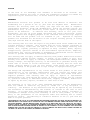
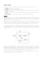
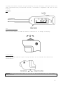
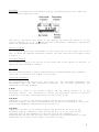
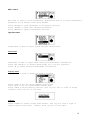
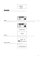
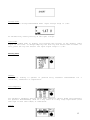
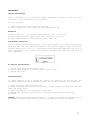
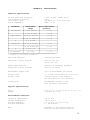
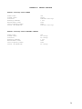
SMART TWEEZERS
R-C-L METER
User’s Manual
Version 1.02
TABLE OF CONTENTS
NOTICE .................................................................................................................................................... 3
WARRANTY ............................................................................................................................................... 3
SAFETY PRECAUTIONS ....................................................................................................................... 4
GETTING STARTED............................................................................................................................... 5
Overview ........................................................................................................................................... 5
Controls ........................................................................................................................................... 6
Power On ........................................................................................................................................... 7
Menu Structures And Functions ......................................................................................... 9
MEASUREMENT FEATURES................................................................................................................. 14
Measuring Resistance............................................................................................................. 14
Measuring Capacitance .......................................................................................................... 15
Measuring Inductance............................................................................................................. 16
Measuring Voltage.................................................................................................................... 16
MAINTENANCE ...................................................................................................................................... 17
LABELLING & VERIFICATION REQUIREMENTS........................................................................ 18
APPENDIX A. SPECIFICATIONS .................................................................................................. 19
APPENDIX B. DEFAULT SETTINGS ............................................................................................. 20
APPENDIX C. SERVICE REQUEST FORM.................................................................................... 21
APPENDIX D. ACCURACY SPECIFICATION ............................................................................... 22
2
NOTICE
To the best of our knowledge this document is believed to be accurate. The
manufacturer reserves the right to change the information and does not assume any
responsibility for omissions and / or errors found in this document.
WARRANTY
Manufacturer warrants this product to be free from defects in materials and
workmanship for a period of one (1) year from the shipment date.
Manufacturer
warrants the following items for ninety (90) days from the date of shipment:
rechargeable batteries, disks and documentation. During the warranty period, the
manufacturer will, at its discretion, either repair or replace any product that
proves to be defective.
To exercise this warranty, write or call your local
distributor. You will be given prompt assistance and return instructions. Please
send the product with shipping prepaid to the indicated service facility. Repairs
will be made and the product will be returned to you.
Repaired or replaced
products are warranted for the balance of the original warranty period, or ninety
(90) days from the date of the repair.
This warranty does not cover the repair of any product whose serial number has been
altered, defaced or removed. This warranty does not cover finishes (scratches on
surface or screen), normal wear and tear, nor does it cover damage resulting from
misuse, dirt, liquids, proximity or exposure of heat, accident, abuse, neglect,
misapplication, operation outside of the environmental specifications, tampering,
unreasonable use, service performed or attempted by unauthorized service centers,
failure to provide reasonable and necessary maintenance.
This warranty does not apply to defects resulting from product modification without
manufacturer’s express written consent, or misuse of any product or part. This
warranty also does not apply to software, non-rechargeable batteries, damage from
battery leakage, and improper polarity of the batteries or problems arising from
normal wear or failure to follow instructions. This warranty does not cover LCD
damage, physical damage to the Jog Dial button, slide switch and reset switch;
electrical damage of the product due to high voltage or improper battery type.
The design and implementation of any circuit based on this product is the sole
responsibility of the customer. Manufacturer does not warrant any damage that
occurs as a result of the user’s circuit or any defects that result from usersupplied products. This warranty does not apply to repairs or replacements
necessitated by any cause beyond the control of factory including, but not limited
to, operation contrary to furnished instructions, shipping accidents, modification
or repair by the user, neglect, accidents or other Acts of God.
The foregoing is in lieu of all other expressed warranties and the manufacturer
does not assume or authorize any party to assume for it any obligation or
liability. The duration of any warranties that may be implied by law (including
the warranties of merchantability and fitness) is limited to the term of this
warranty. In no event shall the manufacturer be liable for special, incidental or
consequential damages arising from ownership or use of this product, or for any
delay in the performance of its obligations under this Warranty due to causes
beyond its control. This Warranty is limited in duration to one (1) year from the
date of original purchase.
THIS WARRANTY IS IN LIEU OF ALL OTHER WARRANTIES, EXPRESSED OR IMPLIED, INCLUDING ANY IMPLIED WARRANTY OF
MERCHANTABILITY OR FITNESS FOR A PARTICULAR USE. THE REMEDIES PROVIDED HEREIN ARE BUYER’S SOLE AND
EXCLUSIVE REMEDIES. NEITHER MANUFACTURER, NOR ANY OF ITS EMPLOYEES SHALL BE LIABLE FOR ANY DIRECT,
INDIRECT, SPECIAL, INCIDENTAL OR CONSEQUENTIAL DAMAGES ARISING OUT OF THE USE OF ITS DEVICES AND SOFTWARE
EVEN IF MANUFACTURER HAS BEEN ADVISED IN ADVANCE OF THE POSSIBILITY OF SUCH DAMAGES. SUCH EXCLUDED
DAMAGES SHALL INCLUDE, BUT ARE NOT LIMITED TO: COSTS OF REMOVAL AND INSTALLATION, LOSSES SUSTAINED AS
THE RESULT OF INJURY TO ANY PERSON, OR DAMAGE TO PROPERTY.
3
SAFETY PRECAUTIONS
The following safety precautions should be observed prior to using this product and
any associated accessories. Although devices and accessories would normally be used
with non-hazardous voltages, there are situations where hazardous conditions may be
present.
This product is intended for use by qualified personnel who recognize shock hazards
and are familiar with the safety precautions required to avoid possible injury.
Read and follow all installation, operation, and maintenance instructions carefully
before using the product. Refer to the manual for complete product specifications.
If the product is used in a manner not specified, the protection provided by the
product may be impaired.
• Inspect the Smart Tweezers case before using. Do not use the device if it
appears to be damaged.
• Do not use the device if it operates abnormally.
• Do not attempt to measure any components in-circuit when your circuit is alive or
active.
To avoid possible damage to Smart Tweezers or to the equipment under test, follow
these guidelines:
• Disconnect circuit power supply and discharge all high-voltage capacitors before
testing
resistance, inductance, or capacitance.
• Do not apply external voltages of more than 1.6 V in the automatic mode.
• Do not apply more than 8V in the voltage measurement mode.
• Use proper terminals and functions for your measurements.
• Use proper batteries to power Smart Tweezers.
Safety symbols and terms
The WARNING heading in this manual indicates dangers that might result in personal
injury or death. Always read the associated information very carefully before
performing the indicated procedure.
The CAUTION heading in the manual indicates hazards that could damage the device.
Such damage may invalidate the warranty.
4
GETTING STARTED
This section summarizes basic operation of Smart Tweezers. In the section:
•
•
•
•
•
Overview – Overview of the device
Controls – Describes buttons and switches
Power-on — Describes the power-on and power-off sequence, the warm-up time, and
default conditions.
Display — Discusses the display format and messages that may appear while using
the device.
Menu structure — Covers menu structure, system settings and features
Overview
Smart Tweezers
(ST) is a portable impedance measuring device. ST is capable of
measuring resistance, capacitance or inductance over a range of more than 8 orders
of magnitude. The device has a basic accuracy better than 1% (resistance) and
operates at four (4) test frequencies.
Smart Tweezers is controlled by a microcontroller that sets measurement conditions,
processes data, operates the display and user interface. The device has a unique
mechanical design that allows manipulation SMT components with size down to 0201.
ST evaluates impedance of a component by measuring the voltage across the component
and current through it. The complex ratio of voltage to current is equal to the
complex impedance. The processor calculates various parameters that are displayed
i.e. R, C or L.
Voltage across the component is generated by the test signal source Vs. Both the
amplitude and frequency of Vs can be set. The voltage is applied to the device
under test (DUT) through the source resistance Rs. Current flows to the virtual
ground of the current amplifier AI, and through the current conversion resistor Ri.
The output of AI provides a signal proportional to the current, I*Ri.
Voltage across the DUT is measured by a separate signal path (amplifier AU), thus
providing a pseudo 4-wire Kelvin connection.
5
Voltage and current signals are processed by the A/D converter. Obtained values are
then corrected using calibration factors, converted to impedance and sent to the
display.
Controls
The Jog Dial Button
The Jog Dial button is used to select a function or to change a setting.
Slide Switch
The slide switch enables input voltage divider for DC VOLTAGE and TRACE mode
measurements.
CAUTION: Do not apply more than 1.6 V to ST if the slide switch is in the Normal
Mode position
6
Power On
Power-on
To turn the Smart Tweezers ON, press the Jog Dial button. The symbol at the bottom
left corner of the display indicates that the device is ON and ready to perform
measurements.
Note: Once powered on, the device will perform the last selected function.
Power-off
ST powers off automatically, the display goes blank and the device goes into a
“sleep” mode if no component has been measured nor the Jog Dial pressed for
approximately 30 seconds. The power off timeout value can be set by changing the
TIMEOUT setting in the DISPLAY menu.
Note: Automatic power-off does not occur if the unit is in the VOLTAGE or TRACE
mode as well as at 10kHz test frequency.
Default power-off settings
By default power-off timeout is 30 seconds in a measurement mode and 30 seconds in
the MENU mode.
7
Display
ST screen is divided into the Primary Display, Secondary Display, Bar Graph and
Test Frequency Indicator areas.
The sign at the bottom left corner of the display indicates that device is on and
ready to measure. A, R, L, C,
indicate Auto, Resistance, Inductance, Capacitance
and Diode measurement mode respectively.
Primary Display
The Primary Display takes the middle of the screen and is the larger one of the
two. It shows the dominant parameter reading. For most functions the display shows
5 digits.
Secondary Display
The Secondary Display is at the top of the screen and is the smaller of the two. It
shows the minor parameter reading.
Bar Graph
The Bar Graph provides an analog representation of the measured major parameter
value and is located at the bottom of the screen.
Displayed Parameters
The measurement mode setting (R, L+R, C+R, C+D, L+Q and AUTO) determines the
measurement type and the displayed parameters. The selected parameters are
indicated on the two displays.
R Mode
Resistance is shown on the Primary Display and the quality factor, Q, on the
Secondary Display. The resistance is either the equivalent series or parallel
resistance of the DUT. Resistance units are mΩ, Ω, kΩ, or MΩ.
L+R Mode
Inductance is shown on the Primary Display and the series resistance on the
Secondary Display. The units of inductance are µH, mH or H. Resistance is the real
part of the impedance. Resistance units are mΩ or Ω.
L+Q Mode
Inductance is shown on the Primary Display and the quality factor Q on the
Secondary Display. Inductance units are µH, mH or H. Q is the ratio of the
imaginary part of the impedance to the real part of the impedance. Q is
dimensionless and the same for both series and parallel representations. A good
inductance has a large L and a small R and thus a high Q.
8
C+R Mode
Capacitance is shown on the Primary Display and the parallel resistance R, is shown
on the Secondary Display. The units of capacitance are pF, nF, or µF. Resistance
units are Ω or kΩ.
C+D
Capacitance is shown on the Primary Display and dissipation factor D on the
Secondary Display. The capacitance is either the equivalent series or parallel
capacitance of the DUT. The units of capacitance are pF, nF, μF or mF. D is the
ratio of the real part of the impedance to the imaginary part of the impedance, or
1/Q. D is dimensionless and the same for series and parallel representations.
A good capacitor has a large C (imaginary) and a small R (real) and thus a low D.
AUTO Mode
ST determines which component model is the most accurate representation of the DUT
and selects the appropriate parameter pair. The determination is made as follows:
for |Q| < 0.15 the R mode is selected.
for Q > +0.15 the L+R or L+Q mode is selected (depends on user settings).
for Q < -0.15 the C+R or C+D mode is selected.
Menu Structures And Functions
This section describes menu structure and parameters setting.
• Main menu — main menu items
• System menu — system menu items
• Sound menu – sound settings
• Display menu — display settings
• Service menu — service functions
• Measurement menu – measurement functions and settings
• Mode menu – measurement modes
• Setting menu – measurement parameters settings
Navigating menus
Turn Jog Dial to move the Selected Item cursor to the desired menu item and push
Jog Dial to select the item. The Actual Setting cursor indicates the current
setting.
9
Main menu
Main menu is used to access System menu, Measurement menu or to return measurement
parameters to the default state using AUTOSET.
Select AUTOSET to reset parameters to the default settings.
Select SYSTEM to change user interface parameters.
Select MEASURE to specify measurement settings.
System menu
System menu is used to access system settings and functions.
Sound menu
Sound menu is used to change sound setting for measurement confirmation.
Select OFF (default) to disable sound except for a Jog Dial operation.
Select ON to enable sound for measurement confirmation.
Display menu
Display menu is used to change the display settings
Select RIGHT to set the “Right Handed” display mode
Select LEFT to set the “Left Handed” display mode
Select CONTR to adjust display contrast. Turn Jog Dial left or right to change
contrast. Press Jog Dial to exit menu
Timeout
Select TIMEOUT to adjust “sleep” mode timeout. Turn Jog Dial left or right to
change timeout value (10sec – 200sec) Press Jog Dial to exit menu.
10
Service Menu
Service menu is used to perform a service function.
OFFSET
Select OFFSET function to perform calibration of the DC voltage offset. Perform
this function before starting a Voltage measurement for better accuracy.
BATTERY
Select BATTERY to measure the battery voltage. Press Jog Dial to exit
SERIAL NUMBER
Select S/N to display device Serial Number.
11
Measurement menu
Measurement modes and settings
Mode menu
The Mode menu is used to set the measurement mode. For automatic measurement
select AUTO (default). Select RES, IND, CAP, DIODE, VOLTAGE or TRACE menu items to
measure desirable component or parameter accordingly.
AUTO mode
Select AUTO
resistance.
mode
for
automatic
measurement
of
inductance,
capacitance
or
Note: In the AUTO mode ST uses by default 1kHz test frequency and has a limited
sensitivity to small capacitance and inductance.
RESistance mode
Enables Resistance measurement mode. See section MEASUREMENT FEATURES for more
information.
INDuctance mode
Enables Inductance measurement mode. See section MEASUREMENT FEATURES for more
information.
CAPacitance mode
Enables Capacitance measurement mode. See section MEASUREMENT FEATURES for more
information.
Diode mode
ST automatically shows polarity of the diode. If the diode is shorted the following
message appears on the display:
12
Voltage mode
Enables the DC voltage measurement mode. Input voltage range is -/+8V.
ST automatically shows polarity of the input voltage.
Trace mode
Select the TRACE mode to display oscilloscope-like picture of the dynamic input
signal in real time. To change sampling rate turn Jog Dial button LEFT or RIGHT. To
exit, press the Jog Dial button. The input signal range is -/+8V.
Setting menu
DEFAULT
The default setting is optimal to perform fully automatic measurements for a
resistance, inductance or capacitance.
Test FREQuency
For automatic frequency setting select AUTO (default). Select fixed test frequency
for specific measurements, such as a very small or a very large capacitance (less
than 50pF or more than 100µF) or inductance.
PERIOD
13
Period menu is used to set the period between measurements.
Note: Short period may reduce the battery life.
R/D/Q
Use
The
C+R
C+D
L+R
L+Q
this menu to set secondary display parameter.
following combinations are allowed:
capacitance + resistance
capacitance + dissipation factor
inductance + resistances
inductance + quality factor
HOLD readings
Allows to hold last reading on display.
TONE
Enable or disable TONE mode for low resistance measurements. See section
MEASUREMENT FEATURES for more information.
MEASUREMENT FEATURES
This section describes specific ST functions and settings.
• Measuring resistance - Covers resistance measurements.
• Measuring capacitance – Covers capacitance measurements.
• Measuring inductance - Covers inductance measurements.
• Testing diodes — Describes testing general-purpose diodes.
• Measuring voltage — Covers DC voltage measurements and TRACE mode for dynamic
signals.
Measuring Resistance
Test frequency
Test signal amplitude
Source impedance
1 kHz
940 +/- 5% mVp-p (typical) Sine wave
620 ohm
14
Test period
1 Sec (default)
Measuring small resistance
There is some small resistance offset which reflects resistance of the tips, and
resistance of the contacts between the tips and DUT. Typical offset value is less
than 25 mΩ. The offset value should be used in calculation of the actual
resistance.
Measurement Options:
There is an additional sound TONE mode controlled by the TONE setting:
If the measured resistance is less than 1 Ohm, sound signal changes the tone
according to the measured resistance. The lower tone represents lower resistance.
If the measured resistance is higher than 1 Ohm – the numbers of beeps represents
the measured resistance.
Range
Number of BEEPS
1 Ω - 10 Ω
1
10 Ω - 20 Ω
2
20 Ω – 30 Ω
3
30 Ω - 40 Ω
4
TONE option is disabled by default.
Measuring Capacitance
Test frequency
Test signal amplitude
Source impedance
Test period
0.1kHz, 1 kHz, 10kHz
940 mVp -p (typical) Sine wave
400 ohm
1 Sec (default)
In AUTO mode Smart Tweezers automatically select the best test frequency and
capable of measuring capacitance from 4 pF to 4999 μF. If you need to measure
capacitance lower than 4 pF select test frequency manually.
Range
Optimal test frequency
<10000pF
10 kHz
10001pF- 1μF
1 kHz
> 1μF
100 Hz
Note: Due to a low test signal level ST can show lower capacitance readings (about
60% of actual value) for some types of ceramic capacitor (e.g. X5R type).
There is some small capacitance offset that reflects capacitance of the tips and
depends on the distance between the tips (i.e. measured component size). The offset
value should be used in calculation of the actual capacitance.
15
Table below shows typical offset values for different component sizes:
Component size
Offset, pF
1206
1.58
0805
1.60
0603
1.65
0402
1.70
Measuring Inductance
Test frequency
Test signal amplitude
Source impedance
Test period
0.1kHz, 1 kHz, 10kHz
940 mVp-p (typical) Sine wave
400 ohm
1 Sec (default)
In AUTO mode ST automatically selects the best test frequency and is capable of
measuring inductance from 1 μH to 1kH. If you need to measure inductance lower than
5μH or more than 1 mH select test frequency manually:
Range
Optimal test frequency
<1 mH
10 kHz
100 μH -100 mH
1 kHz
> 100 mH
100 Hz
Measuring Voltage
DC voltage measurements
Input resistance
Measured range
1 MΩ +/- 1%
-8V to +8V DC
Before making measurements, please perform offset calibration and change the slide
switch position.
Offset calibration procedure:
1. Select CALIBRATION function in the VOLTAGE menu
2. Shorten the tips and wait until message DONE appears on the display
3. Release the tips. The device is ready to perform DC Voltage measurements.
Dynamic signals real time indication
Input voltage range
Input resistance
-8V to +8V AC
1 MΩ
The refresh rate is limited by the LCD performance. User-defined refresh rate
allows seeing either relatively fast or slow events. Before making measurements
please change the slide switch position.
16
MAINTENANCE
General Maintenance
Dirt or moisture on the tips may affect measurement accuracy. Clean the tips
regularly. Do not use abrasives or solvents.
To clean the tips:
1. Shake out any dirt that may be on the tips.
2. Soak a swab with alcohol. Work the swab around each tip.
Batteries
ST uses three 1.4V – 1.5V button type batteries, size 11.2x5.6 mm.
Alkaline type batteries: LR44, 357A, SG13, A76, AG13, L1154 etc.
Air Zinc type batteries: ZA675, VT675, XL675, 675A, etc.
Low Battery Indication
The Low Battery message and battery icon on the display is an indication that the
batteries are low and should be replaced. The warning appears when the battery
voltage drops below 3.45V, i.e. the batteries are about 90% depleted. The unit is
still operational for a short time; however the batteries should be replaced as
soon as possible
To replace the batteries:
1. Remove three screws and lift the cover.
2. Replace the batteries following the “+” and “–“ sign.
3. Secure the cover.
Troubleshooting
If there appears to be a malfunction during an operation of the device, the
following steps should be performed in order to isolate the cause of the problem:
1. Reset device by replacing batteries.
2. Check slide switch position. If necessary, change slide switch position and then
reset the device again.
3. Check the batteries. If necessary, change them.
4. Review the operating instructions for possible mistakes in the operating
procedure.
CAUTION: Except for replacing the battery, a repair of the device should only be
performed by an Authorized Service Center or by qualified service personnel.
17
LABELLING & VERIFICATION REQUIREMENTS
This device complies with Part 15 of the FCC Rules.
Operation is subject to the following two conditions:
1. This device may not cause harmful interference; and,
2. This device must accept any interference received, including interference that
may cause undesired operation.
18
APPENDIX A. SPECIFICATIONS
Technical Specifications
AC test mode Test frequency:
Test frequency accuracy:
Test signal level:
Source impedance:
1 kHz, 10 kHz, 120Hz,100 Hz
0.25%
940 mVp-p +/- 20 mV Sine wave
400Ω +/- 5%
Parameter
Measurement
Range
Resistance
5 Ω to 999 kΩ
< 1.0%
0.1 to 9.9 MΩ
< 5.0%
10 pF to 100 uF
< 3.0%
0.5 pF to 4999 uF
< 5.0%
Capacitance
Basic Measurement
Accuracy*
Q
0.1 to 100
Inductance
10 uH to 99 mH
< 3.0%
0.5 uH to 999 mH
< 5.0%
D
0.01 to 10
DC voltage**
0V to 8V
< 1.0%
* at optimum test frequencies, ranges, without calibration offset.
** required DC voltage offset calibration
Auto mode Read-out:
Dominant parameter
Equivalent circuit diagram:
Parallel for C/R
Serial for L/R
Manual Mode Read-out:
Equivalent circuit diagram:
Dominant or secondary parameter
Parallel or serial
Measurement update rate:
up to 4 measurements per second
Battery Type:
Battery Life:
1.5 V LR44 (357A) Alkaline or Air zinc
70 Hours typical with alkaline,
200 hours with air zinc batteries
Calibration:
Recommended interval 1 year
NIST traceable calibration
Physical Specifications
Size:
Weight:
14.0 x 2.5 x 3.0 cm (3.94 x 0.9 x 1.5 in)
53 grams (0.11 lb)
Environmental Conditions
Operating temperature:
Storage temperature:
Relative Humidity:
Altitude Operating:
0°C to 50°C
-40°C to 70°C
0 % to 90 % (0 °C to 35 °C)
0 – 2000 meters
EMC:
According to CE regulation 89/336,
Emission according FCC15 Class B.
19
APPENDIX B. DEFAULT SETTINGS
Default settings after RESET
SOUND mode:
DISPAY mode:
Contrast:
Readings PERIOD:
Measurement mode:
Test frequency mode:
Offset CALIBRATION:
OFF
Right
FACTORY settings
1 sec
AUTO
AUTO
FACTORY settings
Default settings after AUTOSET command
SOUND mode:
DISPAY mode:
Contrast:
Readings PERIOD:
Measurement mode:
Test frequency mode:
Offset CALIBRATION:
OFF
No change
No change
1 sec
AUTO
AUTO
No change
20
APPENDIX C. SERVICE REQUEST FORM
Model No. _______________ Serial No. __________________ Date _______________
Name
______________________________________________________________________
Company ____________________________________________________________________
Address ____________________________________________________________________
____________________________________________________________________
E-mail
________________________ Telephone No ______________________
List all settings, describe problem and check boxes that apply.
____________________________________________________________________________
____________________________________________________________________________
Power
□ Problem on power-up
□ Device does not turn-off
□ Other_____________________________________________________________________
LCD
□ No image on LCD
□ Missing vertical or horizontal lines
□ Bad contrast
□ Other_____________________________________________________________________
Mechanical
□ Jog Dial
□ Slide Switch
□ Tips
□ Other_____________________________________________________________________
Measurements
□ SMT component
□ non-SMT component
□ Is it an in-circuit measurement?
____________________________________________________________________________
□ Capacitor
□ Inductor □ Resistor
Type (ceramic, tantalum, etc)
Value (uF, pF, uH, Ω, etc.)
___________________________________________
___________________________________________
Test Frequency? ________ Ambient temperature?__________
Humidity? _________
□ Other______________________________________________________________________
□ Additional information (attach any additional sheets as necessary)
Show a block diagram of your measurement including all devices connected
(whether power is turned on or not). If applicable, describe signal source.
______________________________________________________________________________
______________________________________________________________________________
______________________________________________________________________________
□ Calibration only (Certificate of calibration required)
Be sure to include your name and phone number or e-mail on this service form.
21
APPENDIX D. ACCURACY SPECIFICATION
Parameter
Measurement
Range
Resistance
1Ω to 999 kΩ
< 1.0%
0.1 to 9.9 MΩ
< 5.0%
10 pF to 100 uF
< 3.0%
0.5 pF to 4999 uF
< 5.0%
10 uH to 99 mH
< 3.0%
0.5 uH to 999 mH
< 5.0%
0V to +/-8V
< 1.0%
Capacitance
Inductance
DC voltage**
*
**
Basic Measurement
Accuracy*
at optimum test frequency, ranges, without calibration offset
required DC voltage offset calibration
Typical offset:
Resistance
≤ 25 mΩ
Capacitance
1.65 pF
Inductance
0.15 uH
Offset value should be subtracted from measurement result for small value
components (R < 10Ω, C < 100 pF, L < 10 uH).
Parameter
Measurement Range Test frequency
Resistance
< 9.9 MΩ
1 kHz
Capacitance
< 9999 pF
10 kHz
10000 pF to 1 uF
> 1 uF
Inductance
1 kHz
100 Hz
0.5 uH to 99 uH
10 kHz
100 uH 99 mH
1 kHz
> 100 mH
0.1 kHz
Maximum measurement ranges
Resistance R:
Capacitance C:
Inductance L:
Quality factor Q:
Dissipation factor D:
DC Voltage V:
0.05 Ω to 9.9 MΩ
0.5 pF to 4999 uF
0.5 uH to 999 mH
0.002 to 500 *
0.002 to 500 *
0 to +/-8V
Maximum resolution
Impedance/Resistance Z or RAC:
Capacitance C:
Inductance L:
Quality factor Q:
Dissipation factor D:
Phase angle F:
DC voltage V:
10 mΩ
0.1 pF
0.1 uH
0.001
0.001
0.1 deg
0.8 mV
* indication of the parameter not implemented in some versions
22