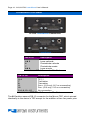
1
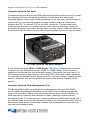
Page 2 · 213/215 DIL LaserMount User’s Manual Table of Contents Introduction ............................................................................................... 3 Installation and Use................................................................................... 4 Connector Pin-Outs ................................................................................ 10 Technical Specifications ......................................................................... 12 Mechanical Specifications ...................................................................... 13 Laser Diode Protection............................................................................ 17 Warranty .................................................................................................. 18 Service and Support ............................................................................... 18 213/215 DIL LaserMount User’s Manual · Page 3 Introduction Thank you for choosing the 213 or 215 DIL LaserMount from Arroyo Instruments. The DIL LaserMount is designed for high performance and long term use, with innovative features not found in other DIL mounts. The 213 and 215 DIL LaserMounts provide the same functionality as our previous 212 and 214 mounts, but with significant new features. An optional fan base is available that significantly increases the thermal performance of both the 213 and 215. Simply remove the standard base and replace with the fan base, and either use an external 12V DC supply or the builtin fan supply of our 5240 or 5300 Series TECSource temperature controllers to power the fan. For applications requiring case temperature control, the 215 integrates a TEC (Peltier) cooler for precise control of the package temperature. With an operating range of -5°C to 85°C, the 215 should cover most of your case temperature control needs. The DIL LaserMount also offers all the features you would expect from a modern DIL laser diode fixture, including: Designed to be quickly integrated with Arroyo’s LaserSource and TECSource instruments. Industry-standard D-sub connectors and pin-outs allow for quick integration into existing laser applications. Screw terminals for all 14 pins of the device, allowing for easy, solderless configuration of the fixture. The 215 TEC DIL LaserMount features three standard connectors, eliminating the need for custom cabling to the two TEC interfaces. Optional fan base (p/n 200-FAN) which significantly increases the efficiency of the heat sink. Optional fiber management tray (p/n 200-TRAY) for managing the DIL’s fiber output. Optional cover (p/n 200-C), which improves the temperature stability of the system and provides protection for the device. Page 4 · 213/215 DIL LaserMount User’s Manual Installation and Use Wiring the mount to your device Start by configuring the wiring of the mount to match your DIL laser. To do this, remove the four screws from the bottom of the fixture and lift off the base plate. This will give you access to the screw terminals inside the fixture. Internal Wiring Example Using the wiring guide below, connect the wires to the appropriate pins of the DIL. The wires are color coded for easy identification. 213/215 DIL LaserMount User’s Manual · Page 5 Signal Color Laser Anode Red Laser Cathode Black Photodiode (PD) Anode Green Photodiode (PD) Cathode White Chassis Ground (GND) Brown TE (+) Orange TE (-) Yellow Thermistor Blue Thermistor Violet Fixture Wiring Guide There is a black 2-pin connector for use with the optional 200-FAN fan base. If you will not be using the fan base, simply leave the connector loose inside the housing. NOTE Earth Grounding Considerations The DB-9 and DB-15 connectors are electrically connected to the housing and 8mm banana jack. Depending on the wiring of your cables and instruments, this may or may not provide earth grounding of the fixture. Make sure the cable shell is earth grounded on both ends of the cable, and that the instrument makes connection from its connector to earth ground. If in doubt, you can also use a grounding strap from the 8mm banana jack directly to earth ground. Page 6 · 213/215 DIL LaserMount User’s Manual Using the Optional Fan Base The optional fan base (p/n 200-FAN) replaces the existing bottom cover, so start by removing the four screws on the bottom of the fixture and setting the standard bottom cover aside. Before screwing on the fan base, you first need to plug the fan in. You will find a black, two-pin socket inside the fixture that is wired to the TEC (or Mount TEC for the 215) connector. The fan base has a matching two-pin plug. It is easiest to place the mount on its back, insert the plug into the socket, and lower the fan base onto the mount. Take care that you do not pinch the fan wires (or any other wires) between the mount and the base. 215 with Optional Fan Base Installed If you will be using the 5240 or 5300 Series TECSource temperature controller to power the fan, make sure to use 1260B or 1262B cables, which have the additional connections for the fan power supply. Otherwise, you can use a 12V DC external power supply with a 2.1mm round DC power jack (center positive). It is possible to operate the fan as low as 6.5V if you would like to reduce the fan noise or vibration, but low fan speeds will reduce the thermal capacity of the mount. Using the Optional Fiber Management Tray The 213 and 215 offers an optional fiber management tray (p/n 200-TRAY), which makes managing excess fiber much simpler by providing a protected area to coil the fiber. Unlike other solutions that use ties to retain the fiber, our fiber tray has an upper lip that catches the fiber, retaining it gently without needing any ties. To install the tray, simply use the provided screws. Note that if you will be using the cover and screwing it down, you will need to install only the front two screws, as the socket head screws that come with the cover will use the rear two threaded holes. 213/215 DIL LaserMount User’s Manual · Page 7 Mount with Fiber Management Tray Installed Using the Optional Cover For applications that demand the best in thermal stability, a cover is available for the 213 and 215 to insulate the device from air currents that can otherwise cause instability in the device and cold plate. The cover also provides physical protection of the laser by preventing outside contact to the case or cold plate. Two alignment pins locate the cover on the mount and prevent it from sliding around when the screws are not installed. For more permanent installations, two socket head screws are provided that can bolt the cover to the mount to prevent removal and also add additional protection for the device. The cover can be used in conjunction with the fiber tray. Mount with Cover Installed Page 8 · 213/215 DIL LaserMount User’s Manual Connecting to the Laser Diode Driver and TEC Controller Next, connect the DIL LaserMount to your laser diode driver and temperature controller. For the 215 TEC DIL LaserMount, you will need a second temperature controller for the case temperature control. NOTE Arroyo Instruments offers Laser and TEC cables designed to connect directly between our LaserSource and TECSource products. If you use your own cables, ensure the connections are properly made between the instrument and the mount, and that proper grounding techniques are used. The pin-out of the connectors can be found later in this document. WARNING Be sure you are properly ESD protected before handling your laser. For additional information, read the section titled “Laser Diode Protection” later in this manual. 213/215 DIL LaserMount User’s Manual · Page 9 Mounting your device Remove any screws from the mounting plate. Open the ZIF socket by placing the lever in the up position, and insert your device. Using the two 4-40 screws provided with the mount, screw the DIL to the mounting plate, but do not overtighten, as you can strip the threads in the mounting plate. Lower the ZIF socket lever into horizontal position to make electrical contact with the laser. Device Loaded Your mount is now ready for use. Additional technical information can be found below. Page 10 · 213/215 DIL LaserMount User’s Manual Connector Pin-Outs 213 DIL LaserMount Connectors 215 TEC DIL LaserMount Connectors DB-9 Pin Description 1–3 No connection 4&5 Laser cathode 6 Photodiode cathode 7 Photodiode anode 8&9 Laser anode Laser DB-9 Connector Pin-Out DB-15 Pin Description 1, 2 TE (+) 3, 4 TE (–) 7 Thermistor 8 Thermistor 11 Fan+ (213 only, 215 no connection) 12 Fan– (213 only, 215 no connection) 5, 6, 9, 13 - 15 No connection TEC DB-15 Connector Pin-Out The 215 adds a second DB-15 connector for the Mount TEC, which pinned identically to the device’s TEC except for the addition of two fan power pins: 213/215 DIL LaserMount User’s Manual · Page 11 DB-15 Pin Description 1, 2 TE (+) 3, 4 TE (–) 7 Thermistor 8 Thermistor 11 Fan+ 12 Fan– 5, 6, 9, 13 - 15 No connection Mount TEC DB-15 Connector Pin-Out (215 Only) Fan Power Connection The optional fan base can be powered either through a 2.1mm round DC jack (center positive) located on the rear of the fan base, or via pins 11 & 12 on the Mount TEC DB-15 connector (see above). Using the DC jack will disconnect the DB-15 fan power connection, preventing simultaneous connection of two power supplies to the fan. Page 12 · 213/215 DIL LaserMount User’s Manual Technical Specifications FICATIONS 213 DIL LaserMount LASER PACKAGE SUPPORTED Package INPUT CONNECTOR Laser Diode Laser TEC THERMAL PERFORMANCE Without fan base1 With fan base1 215 TEC DIL LaserMount LASER PACKAGE SUPPORTED Package TEMPERATURE CONTROL Temperature Range (°C)2 Sensor Type TE Module INPUT CONNECTOR Laser Diode Laser TEC Mount TEC THERMAL PERFORMANCE Without fan base3 With fan base3 Optional Fan Base Connector Voltage / current GENERAL Size (H x W x D) [in(mm)] Fixture mounting holes Recommended device mounting screws 1 14-pin DIL, 8-pin Mini-DIL DB-9, male DB-15, male 3.0°C/W 1.2°C/W 14-pin DIL -5 to +85 10kΩ Thermistor Imax = 3.7A Vmax = 3.6V DB-9, male DB-15, male DB-15, male 1.75W 3W 2.1mm round, center positive 12V DC, 150mA 2.15 (55) x 3.50 (89) x 5.00 (127) ¼-20 through-hole, 3” on center (x2) 4-40 x ¼” socket head cap screw (maximum penetration depth ¼”) At 25°C ambient Temperature control range is dependent on the power dissipated into the heat sink. Mounting fixture to an optical table will increase the heat dissipation capability. 3 At 0°C delta from ambient, 25°C ambient temperature 2 213/215 DIL LaserMount User’s Manual · Page 13 Mechanical Specifications 3.50 88.9 3.00 76.2 1.10 27.9 2.30 58.4 2.40 61 2X .27 6.8 5.00 127 1.50 38.1 .20 5.1 4X 6-32 Top View 2X 4-40 .02 0.6 .75 19.1 .25 6.4 .24 6 Detail View of Mounting Hole Pattern Page 14 · 213/215 DIL LaserMount User’s Manual .59 15 2.15 54.7 1.65 41.8 1.30 32.9 .15 3.7 .62 15.7 1.07 27.3 2.56 65.1 213 Rear View .59 15 2.15 54.7 1.65 41.8 1.30 32.9 .15 3.7 .62 15.7 1.07 27.3 2.56 65.1 215 Rear View 2.82 71.7 2.32 58.9 1.97 50 1.29 32.8 .72 18.2 1.75 44.5 213 Review View with Fan Base 213/215 DIL LaserMount User’s Manual · Page 15 4.30 109.2 2.70 68.6 5.40 137.2 4.80 121.9 4X 4-40 .375 [9.5] 4X 6-32 X .25 LONG PHILLIPS FLAT HEAD, UNDERCUT, MACHINE SCREW 3.50 88.9 .50 12.7 .10 2.5 213 with Fiber Tray Page 16 · 213/215 DIL LaserMount User’s Manual 2.30 58.4 3.35 85.1 2X 6-32 X 1.00 LONG SOCKET HEAD CAP SCREW .93 23.6 2.58 65.4 213 with Cover 213/215 DIL LaserMount User’s Manual · Page 17 Laser Diode Protection Electrostatic discharge and current spikes can be a significant cause of damage to laser diodes, but when proper precautions are taken, these risks can be greatly reduced or eliminated. Arroyo Instruments’ controllers offer state-of-art laser diode protection, but no instrument can fully shield the laser from damage. Please take these considerations into account when operating your laser: 1. 2. 3. 4. 5. 6. Always set the current limit at or below the maximum current your laser can handle. This prevents the device from accidentally driving the current too high, either via the set point or from the modulation port. This also provides additional current limiting protection from ESD. Always work in an ESD safe operating environment, including the use of wrist straps, ESD grounded work surfaces and floors, and ESD-safe tools. Where the AC power to the laser driver to temperature controller may be noisy, use isolation transformers or uninterruptible power supplies that provide isolation. Make sure all cables are securely connected and fastening screws are screwed in tight. Do not route power cords or other cables in parallel with the laser or temperature controller cables, as coupling may occur between the cables and inject noise into the laser diode. While it is not possible to create a ground loop through the LaserSource because of it’s isolation of all inputs, it is possible when using other equipment. Ensure that any other equipment is properly isolated to avoid any ground loop problems. For additional ESD protection, adding 3.5μH (Mouser P/N 542-FB73-287) ferrite beads as close to the laser diode as possible is recommended. One ferrite bead should be used on each laser diode and photodiode diode anode and cathode, with the wire going through the bead at least twice (two turns). Page 18 · 213/215 DIL LaserMount User’s Manual Warranty Arroyo Instruments warrants this product to be free from defects in material and workmanship under normal use and service for a period of one (1) year from date of shipment. It does not apply when the product has been misused, altered or damaged by accident or abnormal conditions of operation. If found to be defective during the warranty period, the product will either be repaired or replaced at Arroyo Instruments's option. THIS WARRANTY IS IN LIEU OF ALL OTHER WARRANTIES, EXPRESSED OR IMPLIED, INCLUDING IMPLIED WARRANTIES OF MERCHANTABILITY OR FITNESS FOR ANY PARTICULAR PURPOSE. ARROYO INSTRUMENTS SHALL NOT BE LIABLE FOR ANY INDIRECT, SPECIAL, OR CONSEQUENTIAL DAMAGES RESULTING FROM THE PURCHASE OR USE OF ITS PRODUCTS. Service and Support For service and support, contact your local distributor or Arroyo Instruments. Telephone: Facsimile: Email: Web: Address: +1 (805) 543-1302 +1 (805) 543-1303 [email protected] http://www.arroyoinstruments.com 624 Clarion Court San Luis Obispo, CA 93401 USA 213/215 DIL LaserMount User’s Manual · Page 19 NOTES: Copyright © 2014, Arroyo Instruments, All Rights Reserved 530-1038 Rev A